EP0401761B1 - Pompe étanche à entraînement magnétique - Google Patents
Pompe étanche à entraînement magnétique Download PDFInfo
- Publication number
- EP0401761B1 EP0401761B1 EP90110632A EP90110632A EP0401761B1 EP 0401761 B1 EP0401761 B1 EP 0401761B1 EP 90110632 A EP90110632 A EP 90110632A EP 90110632 A EP90110632 A EP 90110632A EP 0401761 B1 EP0401761 B1 EP 0401761B1
- Authority
- EP
- European Patent Office
- Prior art keywords
- impeller
- magnetic force
- magnet
- casing
- bearing
- Prior art date
- Legal status (The legal status is an assumption and is not a legal conclusion. Google has not performed a legal analysis and makes no representation as to the accuracy of the status listed.)
- Expired - Lifetime
Links
Images


Classifications
-
- F—MECHANICAL ENGINEERING; LIGHTING; HEATING; WEAPONS; BLASTING
- F04—POSITIVE - DISPLACEMENT MACHINES FOR LIQUIDS; PUMPS FOR LIQUIDS OR ELASTIC FLUIDS
- F04D—NON-POSITIVE-DISPLACEMENT PUMPS
- F04D29/00—Details, component parts, or accessories
- F04D29/04—Shafts or bearings, or assemblies thereof
- F04D29/046—Bearings
- F04D29/047—Bearings hydrostatic; hydrodynamic
-
- F—MECHANICAL ENGINEERING; LIGHTING; HEATING; WEAPONS; BLASTING
- F04—POSITIVE - DISPLACEMENT MACHINES FOR LIQUIDS; PUMPS FOR LIQUIDS OR ELASTIC FLUIDS
- F04D—NON-POSITIVE-DISPLACEMENT PUMPS
- F04D13/00—Pumping installations or systems
- F04D13/02—Units comprising pumps and their driving means
- F04D13/021—Units comprising pumps and their driving means containing a coupling
- F04D13/024—Units comprising pumps and their driving means containing a coupling a magnetic coupling
- F04D13/026—Details of the bearings
-
- F—MECHANICAL ENGINEERING; LIGHTING; HEATING; WEAPONS; BLASTING
- F04—POSITIVE - DISPLACEMENT MACHINES FOR LIQUIDS; PUMPS FOR LIQUIDS OR ELASTIC FLUIDS
- F04D—NON-POSITIVE-DISPLACEMENT PUMPS
- F04D13/00—Pumping installations or systems
- F04D13/02—Units comprising pumps and their driving means
- F04D13/06—Units comprising pumps and their driving means the pump being electrically driven
- F04D13/0646—Units comprising pumps and their driving means the pump being electrically driven the hollow pump or motor shaft being the conduit for the working fluid
-
- F—MECHANICAL ENGINEERING; LIGHTING; HEATING; WEAPONS; BLASTING
- F04—POSITIVE - DISPLACEMENT MACHINES FOR LIQUIDS; PUMPS FOR LIQUIDS OR ELASTIC FLUIDS
- F04D—NON-POSITIVE-DISPLACEMENT PUMPS
- F04D13/00—Pumping installations or systems
- F04D13/02—Units comprising pumps and their driving means
- F04D13/06—Units comprising pumps and their driving means the pump being electrically driven
- F04D13/0666—Units comprising pumps and their driving means the pump being electrically driven the motor being of the plane gap type
-
- F—MECHANICAL ENGINEERING; LIGHTING; HEATING; WEAPONS; BLASTING
- F04—POSITIVE - DISPLACEMENT MACHINES FOR LIQUIDS; PUMPS FOR LIQUIDS OR ELASTIC FLUIDS
- F04D—NON-POSITIVE-DISPLACEMENT PUMPS
- F04D29/00—Details, component parts, or accessories
- F04D29/04—Shafts or bearings, or assemblies thereof
- F04D29/046—Bearings
- F04D29/0465—Ceramic bearing designs
-
- F—MECHANICAL ENGINEERING; LIGHTING; HEATING; WEAPONS; BLASTING
- F04—POSITIVE - DISPLACEMENT MACHINES FOR LIQUIDS; PUMPS FOR LIQUIDS OR ELASTIC FLUIDS
- F04D—NON-POSITIVE-DISPLACEMENT PUMPS
- F04D29/00—Details, component parts, or accessories
- F04D29/04—Shafts or bearings, or assemblies thereof
- F04D29/046—Bearings
- F04D29/0467—Spherical bearings
-
- F—MECHANICAL ENGINEERING; LIGHTING; HEATING; WEAPONS; BLASTING
- F04—POSITIVE - DISPLACEMENT MACHINES FOR LIQUIDS; PUMPS FOR LIQUIDS OR ELASTIC FLUIDS
- F04D—NON-POSITIVE-DISPLACEMENT PUMPS
- F04D29/00—Details, component parts, or accessories
- F04D29/04—Shafts or bearings, or assemblies thereof
- F04D29/046—Bearings
- F04D29/049—Roller bearings
-
- F—MECHANICAL ENGINEERING; LIGHTING; HEATING; WEAPONS; BLASTING
- F16—ENGINEERING ELEMENTS AND UNITS; GENERAL MEASURES FOR PRODUCING AND MAINTAINING EFFECTIVE FUNCTIONING OF MACHINES OR INSTALLATIONS; THERMAL INSULATION IN GENERAL
- F16C—SHAFTS; FLEXIBLE SHAFTS; ELEMENTS OR CRANKSHAFT MECHANISMS; ROTARY BODIES OTHER THAN GEARING ELEMENTS; BEARINGS
- F16C33/00—Parts of bearings; Special methods for making bearings or parts thereof
- F16C33/02—Parts of sliding-contact bearings
- F16C33/04—Brasses; Bushes; Linings
- F16C33/043—Sliding surface consisting mainly of ceramics, cermets or hard carbon, e.g. diamond like carbon [DLC]
-
- H—ELECTRICITY
- H02—GENERATION; CONVERSION OR DISTRIBUTION OF ELECTRIC POWER
- H02K—DYNAMO-ELECTRIC MACHINES
- H02K5/00—Casings; Enclosures; Supports
- H02K5/04—Casings or enclosures characterised by the shape, form or construction thereof
- H02K5/12—Casings or enclosures characterised by the shape, form or construction thereof specially adapted for operating in liquid or gas
- H02K5/128—Casings or enclosures characterised by the shape, form or construction thereof specially adapted for operating in liquid or gas using air-gap sleeves or air-gap discs
- H02K5/1282—Casings or enclosures characterised by the shape, form or construction thereof specially adapted for operating in liquid or gas using air-gap sleeves or air-gap discs the partition wall in the air-gap being non cylindrical
-
- H—ELECTRICITY
- H02—GENERATION; CONVERSION OR DISTRIBUTION OF ELECTRIC POWER
- H02K—DYNAMO-ELECTRIC MACHINES
- H02K7/00—Arrangements for handling mechanical energy structurally associated with dynamo-electric machines, e.g. structural association with mechanical driving motors or auxiliary dynamo-electric machines
- H02K7/08—Structural association with bearings
- H02K7/086—Structural association with bearings radially supporting the rotor around a fixed spindle; radially supporting the rotor directly
- H02K7/088—Structural association with bearings radially supporting the rotor around a fixed spindle; radially supporting the rotor directly radially supporting the rotor directly
-
- H—ELECTRICITY
- H02—GENERATION; CONVERSION OR DISTRIBUTION OF ELECTRIC POWER
- H02K—DYNAMO-ELECTRIC MACHINES
- H02K7/00—Arrangements for handling mechanical energy structurally associated with dynamo-electric machines, e.g. structural association with mechanical driving motors or auxiliary dynamo-electric machines
- H02K7/10—Structural association with clutches, brakes, gears, pulleys or mechanical starters
- H02K7/11—Structural association with clutches, brakes, gears, pulleys or mechanical starters with dynamo-electric clutches
Definitions
- This invention relates to a so-called magnet pump according to the preamble of claim 1.
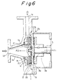
- the magnet pump shown in Fig. 6 is adapted to rotatably drive the pump impeller utilizing the magnet coupling between permanent magnets and the pump comprises a pump casing 1 including an inlet cover 1a joined to a back cover 1b and including a pump chamber 1c containing the impeller 2, a suction port 1d for introducing fluid to be pumped and a discharge port 1e for discharging the pressurized fluid.
- the back cover 1b is provided on its non-liquid-contacting portion with a magnet yoke 3a fixed to a main shaft 3 rotatably driven by a drive source, such as a motor (not shown), and a permanent magnet 3b is annularly provided on a surface of the magnet yoke 3a opposing the back cover 1b.
- An annular permanent magnet 2c is embedded in a similarly annular magnet yoke 2b within the impeller 2 which is rotatably contained in the pumping chamber 1c, and the impeller 2 is rotatably driven by the main shaft 3 to displace the fluid.
- the annular permanent magnet 2c and permanent magnet 3b may be formed in a single ring-like permanent magnet or of a plurality of annularly arranged permanent magnets.
- the N- and S-poles should be alternately and circumferentially arranged.
- the force acting on the impeller 2 when it is not moved is mainly the magnetic attraction force F1 of the permanent magnets 2c, 3b and thus the impeller 2 is urged towards the back cover 1b and the pump is activated in such a condition. Therefore, the back cover 1b is provided on its side with a fixing-part bearing 1f and the impeller 2 also on its back surface with a rotating-part bearing 1g to thereby support the thrust and radial loads.
- a slide member on the rotating part (bearing 1g) and a slide member on the fixed part (bearing 1f) are each referred to as a bearing and a pair of such slide members also to simply be referred to as a bearing herein.
- the arrow indicating the magnetic attraction force F1 acting on the impeller 2 does not exactly indicate where the force acts upon, but merely shows a component of the magnetic attraction force in the direction of the rotary shaft axis.
- the inlet cover 1a is provided with a fixed-part bearing 1h, and a rotating-part bearing 2j is provided on a part opposing the bearing 1h of the impeller 2.
- the strength of the magnetic attraction force F1 generated by the permanent magnets 2c, 3b varies due to the fluid force applied to the impeller 2, and the magnitude of the thrust force F2 also varies due to the fluid pressure.
- the magnetic attraction force F1 and the thrust force F2 are equal to each other, and as the valve is further opened the magnetic attraction force F1 becomes larger than the thrust force F2 and the impeller 2 rotates while urged towards the back cover 1b (point C).
- the impeller 2 is rotating at a position spaced away from the inlet cover 1a and therefore the bearing clearance between the high and lower pressure regions becomes sufficiently large to allow the pressurized fluid to escape to the suction portion thereby reducing the pump outlet pressure below the point B.
- the pump operating point moves along the solid line to the point D.
- the valve then gradually closes the pump operating point moves to the point E through the point C since the magnetic attraction force F1 is larger than the thrust force F2.
- the magnetic attraction force F1 and the thrust force F2 are equal to each other.
- the impeller 2 rotates while being urged by the thrust force F2 towards the inlet cover 1a and the operating point reaches the point F.
- the pump pressure-flow rate characteristics curve depicts a hysteresis curve, and accordingly the impeller 2 rotates while biased either towards the inlet cover 1a or towards the back cover 1b depending upon the operating condition, as described above.
- a further conventional magnet pump shown in Fig. 7 is adapted to directly rotatably drive the magnet embedded in the impeller with the electromagnetic force generated by the stator.
- the basic structure of the casing 1 and impeller 2 is the same as those of the conventional pump shown in Fig. 6, but it differs in that the driving magnetic force mechanism constituting the means for rotatably driving the impeller 2 is a stator 5.
- the stator 5 for driving the magnet embedded in the impeller is mounted on the non-liquid-contacting portion of the back cover 1b at a position opposing the magnet of the impeller, the stator 5 having coils 5a wound on an annularly arranged core 5b, the coils 5a being supplied with power from a power source control circuit not shown, thereby rotatably driving the impeller 2 on the operating principle of a so-called brushless motor.
- the magnet pump of Fig. 7 also exhibits similar behavior on the characteristic curve to those of the pump of Fig. 6 described above, and the impeller 2 rotates while based either towards the inlet cover 1a or towards the back cover 1b depending upon the pump operating condition.
- the impeller 2 is, in operation, shifted in the direction of the rotary shaft axis 20 thereof depending upon the operating condition.
- there are operating regions i.e., an operating region (A ⁇ B, F ⁇ A on the characteristic curve) in which the resultant force of the magnetic attraction force F1 acting between the permanent magnet 2c embedded in the impeller 2 and the driving-part permanent magnet 3b (or stator 5) for rotatably driving it and the thrust force F2 due to the fluid acting on the impeller is directed towards the inlet cover 1a
- an operating region (C ⁇ D, D ⁇ E) in which the resultant force is reversely directed towards the back cover 1b
- an unstable region B ⁇ C, E ⁇ F which is the transient region between the operating regions, and the position of the impeller may vary depending upon the pump operating conditions in various ways.
- bearings are provided in the respective positions on the sides of the inlet cover 1a and back cover 1b and these bearings must be assembled parallel or perpendicular to each other and this causes problems in the machining and assembling processes of the parts.
- an easily damageable bearing involves the risk of bearing debris entering into such a fluid, and if a special surface treatment such as a corrosion resistance is applied to the bearing, the layer of surface treatment may be peeled off; these represent potentially serious problems which are likely to occur even if the pump is well maintained.
- the document DE-B-20 58 062 discloses a generic magnet pump according to the preamble of claim 1.
- the fluid inlet passage for communicating between a suction port and a pumping chamber passes through the center portion of the magnetic force driving mechanism.
- the impeller is of the closed type, i.e. impeller vanes are sandwiched between a front element and a rear element. This arrangement of the impeller results in that the pump pressure acts onto the rear element and creates a pressure thrust force acting on the impeller directed towards the suction port. The magnetic attraction force acting on the impeller is also directed towards the suction port.
- the bearing of this known magnet pump comprises a stationary part fixed to the casing and a moving part fixed to the impeller.
- the gap between these two bearing parts forms a hydrodynamic bearing.
- the gap of this bearing and the surfaces of the two bearing parts are spherical.
- the bearing surfaces extend up to the outer circumference of the impeller. Due to this geometry of the bearing parts, the impeller has a substantial length in its axial direction and the bearing surfaces of the bearing parts cover a substantial surface of the impeller.
- the magnetic means consists of a permanent magnet embedded in the impeller, the permanent magnet being disk shaped and being oriented perpendicular to the axis of the impeller. Further, the outer diameter of the bearing is smaller than the inner diameter of the permanent magnet.
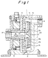
- Fig. 1 is a vertical sectional view of a first embodiment and also a third embodiment of the magnet pump, comprising a pump casing 1 including an inlet cover 1a having a suction port 1d for fluid and a back cover 1b having a discharge port 1e for pressurized fluid, the inlet and back covers 1a and 1b defining a pumping chamber 1c containing an impeller 2, a rotating-part bearing 1g and a fixed-part bearing 1f serving as a moving part and a stationary part, respectively, being provided on the impeller 2 and inlet cover 1a, and the pumping chamber 1c and the suction port 1d being in communication with each other through an inlet passage 1k.
- the material of those parts which constitute the casing 1 should have corrosion resistance to a delivery fluid.
- the impeller 2 rotatably contained in the pumping chamber 1c has an annular permanent magnet 2c serving as magnetic means bonded to and embedded in a surface of an annularly formed magnet yoke 2b adjacent to the inlet cover 1a, which is usually sealed by a known means, such as thermal bonding or welding, using a non-magnetic material, such as nylon or fluorine plastic, to prevent the fluid from reaching the metallic portion.
- the impeller 2 is provided with vanes 2g for establishing the predetermined pump performance and which are attached with a main plate 2h for enhancing the pumping efficiency in the shown embodiment.
- the fixed-part bearing 1f Fixedly secured on or screwed into the inner surface or the portion facing the pumping chamber 1c, of the inlet cover 1a is the fixed-part bearing 1f the concave surface of which faces the side of the impeller 2, and the portion of the impeller 2 facing it in the direction of the axis 20 of the rotary shaft thereof is fixedly fitted with or screwed with the rotating-part bearing 1g, the convex surface of which corresponds to the concave surface of the fixed-part bearing 1f and faces it, and the thrust load in the direction of the axis 20 and the radial load perpendicular thereto are supported by the sliding contact of the bearings 1f and 1g.
- stator 5 for serving as a magnetic force driving mechanism or means for rotatably driving the impeller under the action of magnetic force to the permanent magnet 2c embedded in the impeller 2, it being adapted to generate magnetic force by the power from a power supply not shown, and the fluid inlet passage 1k communicating between the suction port 1d and the pumping chamber 1c is formed in the center portion of the stator 5 along the rotary shaft axis 20 of the impeller 2.
- the fluid entering into the pump passes through the center portion of the magnetic force driving mechanism in the rotary shaft axis 20 of the impeller 2 and is pressurized by the action of the impeller 2 rotating within the pumping chamber 1c and directed therethrough to the discharge port 1e and out to the exterior of the pump.
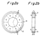
- Figs. 1(a) and (b) are schematic representations diagrammatically showing the power transmission of the magnet pump of the embodiment of Fig. 1, Fig. 1(a) being a vertical sectional view showing the stator 5 and the magnet yoke 2b and Fig. 1(b) being a side elevation as viewed from the right in Fig. 1(a) and the magnet yoke 2b being removed.
- a ring-shaped core 5b of a ferromagnetic material is provided with six projections S1 - S6 formed on its side adjacent to the permanent magnet 2c, and coils k1 - k6 are wound on the projections S1 - S6, respectively.
- the permanent magnet 2c includes eight segmented permanent magnets M1 - M8 arranged in an annular array, each of the permanent magnets M1 - M8 being premagnetized and located so that S-poles and N-poles are alternately positioned on the surface facing the stator 5.
- the permanent magnet 2c is divided into the segmented magnets M1 - M8 to form one annular magnet, if necessary, a single magnet can be used by forming it into an annulus and magnetizing it to provide an alternating arrangement of S- and N-poles, and this is also true of permanent magnets 12, 22 and 32 which will be described below.
- the stator 5 is integrally formed together with the projections S1 - S6 by laminating silicon steel plates or sintering iron powder, and a different number of poles, such as six poles in this embodiment, from those of the permanent magnet 2c (eight poles in this embodiment) is usually selected to ensure the staring operation and smooth rotation of the impeller 2.
- the rotation of the permanent magnet 2c is caused by appropriately changing the supply of direct current to the coils k1 - k6 in accordance with signals from a magnetic pole detecting means, such as a Hall effect element, not shown.
- the magnet pump of Fig. 1 is so operated that the impeller 2 is rotated by supplying power to the stator 5 to pressurize and deliver the fluid.
- the fluid pressure acting on the impeller 2 will create a thrust force for urging the impeller 2 leftward as viewed in Fig. 1.
- the axial component of the force acting from the stator 5 on the impeller 2 always forces the impeller 2 leftward, so that the impeller 2 can continue the operation in a stable position without changing its position at any operating point.
- the impeller 2 is subjected to the gravity and the fluid force acting between the bearings 1f and 1g.
- the gravity has practically no effect, although the direction of the gravitational action varies depending upon the horizontal or vertical positioning of the magnet pump of Fig. 1. Therefore, the effect of the gravity thereon is not further described herein.
- the magnitude of the fluid pressure on the bearings is also not described because if the bearings are operating normally a reaction equal to the load applied thereto is being created.
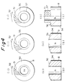
- Fig. 2 shows the second inventive embodiment and the fourth inventive embodiment described below, the magnetic force driving mechanism thereof having a different structure from that of the aforementioned embodiments.
- a permanent magnet for the magnetic force driving mechanism constituting the means for rotatably driving the impeller 2 embedding the permanent magnet under the action of an exterior magnetic force, the permanent magnet is rotatably mounted in the non-liquid-contacting portion of the casing so that the magnetic force thereof directly acts on the permanent magnet embedded in the impeller 2 to rotatably drive the latter.
- the casing 1 having the suction port 1d, the discharge port 1e and the pumping chamber 1c includes the inlet cover 1a and the back cover 1b, and the impeller 2 is contained in the pumping chamber 1c.
- the outside of the casing 1 is reinforced by a back casing cover 11b, an inlet casing cover 11a, and a reinforcing plate 11c secured to the inlet casing cover 11a.
- a ball bearing 10 is secured to the inner periphery of the inlet casing cover 11a positioned on the non-liquid-contacting portion of the casing 1, and an annular permanent magnet 12 is secured to the inner race of the bearing.
- the annular permanent magnet 12 or magnetic force driving mechanism for rotatably driving the impeller 2 is rotatably provided in the non-liquid-contacting portion.
- the permanent magnet 12 is basically in magnetical and mutual attraction with the permanent magnet 2c embedded in the impeller 2. Since the permanent magnet 12 of the magnetic force driving mechanism also has the alternate pole arrangement as shown in Fig. 2(a), similar to the permanent magnet 2 of the impeller 2, as the permanent magnet 12 of the magnetic force driving mechanism rotates the impeller 2 is also rotated in synchronism therewith.
- the permanent magnet 12 of the magnetic force driving mechanism not only directly rotatably drives the impeller 2, but also receives the magnetic action for rotating itself from the stator 5.
- the magnetization of the permanent magnet 12 is so made that the axially aligned poles on the opposite surfaces of the annular permanent magnet 12 have opposite polarities to each other as shown in Figs. 2(a) and (b).
- the permanent magnet 12 has the function of a driving source relative to the impeller 2 and also a function of the driven member relative to the stator 5.
- the permanent magnet 12 is shown in the form of an integral ring-shaped magnet, it may be formed by arranging a plurality of divided permanent magnets in an annulus in which the N- and S-poles are alternately positioned.
- the inlet passage 1k for communicating between the pumping chamber 1c and the suction port 1d passes through the center portions of the stator 5 and permanent magnet 12 of the magnetic force driving mechanism along the axis 20 of the impeller 2.
- the means for rotating the magnetic force driving mechanism may, for example, be constituted by a turbine or motor which is arranged to rotate the permanent magnet 12 through gears, and there is no need for such a turbine or motor to be arranged on the same axis as that of the magnetic force driving mechanism.
- both of the magnetic attraction force F1 acting on the impeller 2 and the thrust force F1 due to the fluid pressure act to urge the impeller 2 towards the magnetic force driving mechanism and the load is supported on the sliding surfaces between the rotating-part bearing 1g secured to the impeller 2 and the fixed-part bearing 1f facing thereto and fixed to the inlet cover 1a, and the impeller 2 can be rotated in a stable position similar to that of the embodiment of Fig. 1.
- the pump shown further comprises a motor cover 7 for containing the stator 5, a connector 7b for receiving power from the power supply not shown and an air supply port 7c for supplying cooling air to portions of the stator 5.
- the magnetic force driving mechanism for rotatably driving the impeller 2 is the permanent magnet
- the magnetic attraction force acting on the impeller also has a centralizing function for holding the impeller in a constant position in a direction perpendicular to the rotary shaft axis, so that the impeller can be held in an appropriate position by the centralizing function due to the magnetic force, even when there is no specific shaft for holding it in a predetermined radial position.
- Fig. 3 shows an embodiment of the fourth invention which has a different structure of the magnetic force driving mechanism from that of the embodiment of Fig. 1. Thus, the difference will mainly be described below.
- the casing 1 having the suction port 1d, the discharge port 1e and the pumping chamber 1c includes the inlet cover 1a and the back cover 1b, and the impeller 2 is rotatably contained in the pumping chamber 1c.
- the outside of the casing 1 is reinforced by a back casing cover 11b, an inlet casing cover 11a, and a reinforcing plate 11c secured to the inlet casing cover 11a.
- a ball bearing 10 is secured to the inner periphery of the inlet casing cover 11a positioned on the non-liquid-contacting portion of the casing 1, and a magnet yoke 23 attached with a permanent magnet 22 of the magnetic force driving mechanism is secured to the inner race of the bearing.
- a magnet yoke 34 attached with a driven-side permanent magnet 32 for receiving the magnetic force from the stator 5 is secured at a screw-threaded portion 35 to an opposite side of the magnet yoke 23 to the impeller 2 so that the permanent magnet 22 of the magnetic force driving mechanism and the driven-side permanent magnet 32 are rotated together with each other.
- the stator 5 for rotating the driven-side permanent magnet 32 is fixedly contained in the motor cover 7 integrally connected with the inlet casing cover 11a positioned in the non-liquid-contacting portion of the casing 1, and a projection S of the core 5b of the stator 5 is opposed to the driven-side permanent magnet 32.
- a magnetic field is created on the projection S of the core 5b to rotate the driven-side permanent magnet 32 opposed to and spaced away from the projection S in the direction of the rotary shaft axis 20 thereof, and the magnet yoke 23 for the magnetic force driving mechanism rotatably supported together with the driven-side magnet yoke 34 is also rotated together with the driven-side magnet yoke 34.
- the permanent magnet 22 of the magnetic force driving mechanism is rotated to create a magnetic driving force for rotating the impeller 2.
- the permanent magnet 2c embedded in the impeller 2 and the permanent magnet 22 of the magnetic force driving mechanism to be provided with the same number of poles and the permanent magnet 32 to also be provided with an appropriate number of alternately polarized poles to provide an optimum power transmission in relation to the stator 5.
- the permanent magnet is provided in the magnetic force driving mechanism for directly rotatably driving the permanent magnet embedded in the impeller 2, and the stator is provided as a means for rotating the magnetic force driving mechanism, and the inlet passage 1k for communicating between the suction port and the pumping chamber 1c is formed in their center portion, i.e., along the rotary shaft axis of the impeller 2.
- the thrust force F2 due to the fluid pressure acting on the impeller 2 and the axial component F1 of the magnetic attraction both act in the direction to urge the impeller 2 towards the magnetic force driving mechanism, and the load is supported on the sliding surfaces between the rotating-part bearing 1g and the fixed-part bearing 1f fixed to the inlet cover 1a and opposed thereto, so that the impeller 2 can be rotated in the stable position similarly in the embodiments shown in Figs. 1 and 2.
- the power transmission between the magnetic force driving mechanism and the impeller 2 utilizes the same principle of permanent magnet coupling as that of the second embodiment and thus the power loss in the course of transmitting the power (magnetic force) is almost negligible as long as the material for the inlet cover 1a and reinforcing plate 11c is appropriately selected.
- Both of the magnetic force driving mechanism and the stator 5 functioning as the means for rotating it are at the non-liquid-contacting portion.
- the energy conversion involving the stator 5 from electric power to the rotary torque is a process which involves a considerable energy loss usually resulting from the magnetic gap.
- the structure for generating the rotary torque in the stator 5 is positioned in the non-liquid-contacting portion, whereby the magnetic gap can be minimized to make the magnetic pump highly effective.
- the pump shown also has the motor cover 7 for containing the stator 5, the connector 7b for receiving power from the power supply not shown, the air supply port 7c for supplying cooling air to portions of the stator 5 and the discharge port 7d of the cooling air.
- the magnetic force driving mechanism has the magnet for applying magnetic force to the impeller for rotation, and there is almost no power loss during the power transmission between the impeller and the magnetic force driving mechanism, if the material of the casing and its reinforcing members interposed between the impeller and magnetic force driving mechanism is appropriately selected, irrespective of the output of the magnet pump and the dimension of the magnetic gap with the result that no heat is generated in the course of the power transmission. Also the magnetic force driving mechanism and the stator for rotating it are located in the non-liquid-contacting portion so that highly efficient power transmission (energy conversion) can be achieved, thus, any heat generation due to the power loss can be avoided, and a highly efficient magnet pump can be provided.
- Figs. 4 and 5 are to explain the components of the preferred embodiment of the magnet pump of the present invention, Fig. 4 being for the bearing and Fig. 5 being for the impeller.
- Fig. 4 schematically shows a bearing suitable for use with the magnet pump of the present invention.
- the bearing is desirably constituted by a dynamic pressure bearing of own-liquid lubricating system using the fluid in the pumping chamber 1c for lubricant, and most preferably a spirally grooved bearing formed with grooves of about 10 microns in depth in one of the sliding surfaces, in view of the large load capacity.
- the bearing material is preferably a ceramic which is a brittle material not easily deformable, and usually may be a ceramic sintered material, such as a silicon carbide sintered material, a silicon nitride sintered material, an aluminum oxide sintered material.
- a thin layer of a highly pure ceramic should be formed the entire surface of the ceramic sintered material.
- a spirally grooved bearing produced by forming a layer about 100 to 200 micron thick of silicon carbide on the surface of a silicon carbide sintered material by a thermal CVD process and then forming spiral grooves in the surface of the CVD layer has excellent corrosion and wear resistance, and the physical property of the substrate of silicon carbide sintered material and the thin layer of silicon carbide formed thereon is analogous which provides a high mutual bonding strength and high thermal and physical shock resistances and high reliability.
- the below-described bearings can be formed of the above-described materials and are basically self-lubricating type dynamic pressure bearings. Fig.
- the sliding surface 50 has a spherical configuration and is formed with spiral grooves 51 therein.
- the surface of the fixed-part bearing not shown has a complementarily concaved spherical configuration.
- An arrow shows the direction of rotation the bearing B, and as the bearing rotates in that direction of rigid fluid film is formed on the sliding surface 50 to provide a balance in response to the load. Due to the spherical shape, the cliding surface 50 can support both the thrust and radial loads.
- Fig. 4(b) shows the rotating-part bearing of a conical, spirally grooved bearing, and the sliding surface of the fixed-part bearing not shown has a complementarily concaved surface.
- the conical, spirally grooved bearing can also support the thrust and radial loads. Particularly, it secures the position of the impeller 2 more positively.
- Fig. 4(c) shows the rotating-part of a quill type spirally grooved bearing described in the prior art and which has a flat spirally grooved bearing portion 56 for supporting the thrust force and a cylindrical spirally grooved bearing portion 57 for supporting the radial force. It is also necessary that the sliding surface of the fixed-part bearing should be complementary to the sliding surfaces 56, 57 of the rotating-part bearing.
- spiral grooves may be provided either on the sliding surface of the rotating-part or fixed-part bearing, and the rotating-part bearings of Figs. 4(a), (b) and (c) can also be attached to the fixed-parts.
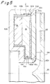
- Fig. 5 is a sectional view of the essential part of the impeller 2, and the iron magnet yoke 2b and the permanent magnet 2c fixed thereto are both of a easily corrosive material. Thus, they are not only sealed by an organic polymer material (nylon, PTFE, PFA, etc.), but also covered by a highly air-tight inorganic material to enhance the corrosion resistance of the metallic material.
- an organic polymer material nylon, PTFE, PFA, etc.
- Upper and lower stream side covers 60b and 60c are made of a good corrosion-resisting resin, such as PFA, the magnet yoke 2b and permanent magnet 2c being contained in the upper and lower stream side covers 60b and 60c, their joined surface 60d is welded to embed the metal parts therein, these being further contained in ceramic containers 61b, 61c the outermost periphery of which is covered with upper and lower stream side impellers 62b and 62c made of PTFE, and their joined surface 62d being welded to seal the rotor portion.
- Blades 63 for pressurizing the fluid are integrally performed with the lower stream side impeller 62c and a main shroud 64 is welded to the blades 63.
- the containers 61b, 61c shown in Fig. 5 are arranged thin films of silicon carbide produced by a thermal CVD process and so their joined portion 61d is sealed by an interposed thin film of PFA.
- the containers 61b, 61c may be formed of quartz and the joined surface 61d can be welded by a known means, such as by a laser, to provide a complete seal.
- the containers can also be prevented from being damaged by the aforementioned interposition of the upper and lower stream side covers 60b and 60c of a resilient material between the metal members, such as the permanent magnet 2c and the magnet yoke 2b, and the brittle containers 61b, 61c.
- the aforementioned containers are formed of a glass material, such as quartz, and the joined surface is completely sealed by welding or thermal bonding means, there will be no need to sealingly encapsulate the metal members as in the case of the upper and lower stream side cover 60b and 60c, but only provide shock absorbing ability to avoid point contact of the metal members and containers.
- the magnetic force driving mechanism is mounted on a non-liquid-contacting portion of the casing at a position facing the impeller in respect to the direction of the rotary shaft axis of the impeller.
- a fluid inlet passage for communicating between the suction port and the pumping chamber is formed to pass through the center portion of the magnetic force driving mechanism.
Landscapes
- Engineering & Computer Science (AREA)
- General Engineering & Computer Science (AREA)
- Mechanical Engineering (AREA)
- Power Engineering (AREA)
- Chemical & Material Sciences (AREA)
- Ceramic Engineering (AREA)
- Fluid Mechanics (AREA)
- Physics & Mathematics (AREA)
- Structures Of Non-Positive Displacement Pumps (AREA)
- Electromagnetic Pumps, Or The Like (AREA)
- Sheets, Magazines, And Separation Thereof (AREA)
- Magnetically Actuated Valves (AREA)
- Fuel-Injection Apparatus (AREA)
Claims (8)
- Pompe à entraînement magnétique, comprenant une roue (2) de type fermé ayant un moyen magnétique (2c) et entraîné en rotation par une force magnétique depuis l'extérieur de la roue,
un carter (1) de pompe comprenant un orifice d'aspiration (1d) et un orifice d'évacuation (1e) et une chambre de pompage (1c), la roue (2) étant logée dans la chambre de pompage (1c) du carter (1) afin qu'elle tourne,
un palier (1f, 1g) placé du côté d'aspiration de la roue (2) et ayant une partie stationnaire (1f) fixée au carter (1) et une partie mobile (1g) fixée à la roue, le palier (1f, 1g) ayant une configuration telle qu'il encaisse la force radiale et la force de poussée agissant sur la roue (2),
un mécanisme (5, 12, 22, 32) d'entraînement par une force magnétique constituant un moyen destiné à appliquer la force magnétique au moyen magnétique (2c) de la roue (2) afin que celle-ci soit entraînée en rotation, le mécanisme (5, 12, 22, 32) d'entraînement par une force magnétique étant monté dans une partie du carter (1) qui n'est pas au contact du liquide, du côté d'aspiration de la roue (2) et étant tourne vers la roue (2) dans la direction de l'axe (20) de l'arbre rotatif de la roue (2), et un passage (1k) d'entrée de fluide destiné à assurer la communication entre l'orifice d'aspiration (1d) et la chambre de pompage (1c), le passage (1k) d'entrée de fluide étant formé afin qu'il passe dans la partie centrale du mécanisme (5, 12, 22, 32) d'entraînement par une force magnétique et le centre du palier (1g, 1f) telle que définie par l'axe de rotation (20) de la roue (2),
caractérisée en ce que
le moyen magnétique est formé par un aimant permanent (2c) enrobé dans la roue (2), en ce que l'aimant permanent (2c) a une forme de disque et est orienté perpendiculairement à l'axe de rotation (20) de la roue (2), et en ce que le diamètre externe du palier (1f, 1g) est inférieur au diamètre interne de l'aimant permanent (2c) qui est enrobé dans la roue (2). - Pompe à entraînement magnétique selon la revendication 1, caractérisée en ce que le mécanisme (5, 12, 22, 32) d'entraînement par une force magnétique comprend un aimant permanent (12, 32) monté afin qu'il tourne sur la partie du carter (1) qui n'est pas au contact d'un liquide.
- Pompe à entraînement magnétique selon la revendication 1, caractérisée en ce que le mécanisme (5, 12, 22, 32) d'entraînement par une force magnétique comporte un stator (5) fixé à la partie du carter (1) qui n'est pas au contact d'un liquide.
- Pompe à entraînement magnétique selon la revendication 1, caractérisée en ce que le mécanisme (5, 12, 22, 32) d'entraînement par une force magnétique comporte un aimant permanent (22) monté afin qu'il puisse tourner sur la partie du carter (1) qui n'est pas au contact d'un liquide, et un stator (5) constituant un moyen de transmission de la rotation ou mécanisme d'entraînement de la force magnétique, le stator (5) étant fixé à la partie du carter (1) qui n'est pas au contact d'un liquide.
- Pompe à entraînement magnétique selon l'une des revendications 1 à 4, caractérisée en ce que l'aimant permanent (2c) enrobé dans la roue (2) est logé dans un récipient formé d'un matériau minéral.
- Pompe à entraînement magnétique selon l'une des revendications 1 à 5, caractérisée en ce que le passage d'entrée (1k) passe dans la partie centrale de la partie fixe (1f) du palier (1f, 1g) fixée au carter (1).
- Pompe à entraînement magnétique selon l'une des revendications 1 à 6, caractérisée en ce que le matériau des parties (1f, 1g) de palier est une céramique, et l'une des parties de palier comporte, dans sa surface de glissement, des gorges (51) formées afin qu'elles créent une pression dynamique.
- Pompe à entraînement magnétique selon la revendication 7, caractérisée en ce que la céramique comporte un substrat d'un matériau de carbure de silicium fritté et une mince couche de carbure de silicium revêtant la surface du substrat qui est déposé par un procédé de dépôt chimique en phase vapeur thermique.
Applications Claiming Priority (6)
| Application Number | Priority Date | Filing Date | Title |
|---|---|---|---|
| JP14117589 | 1989-06-05 | ||
| JP14403389 | 1989-06-08 | ||
| JP144033/89 | 1989-06-08 | ||
| JP141175/89 | 1989-12-06 | ||
| JP123133/90 | 1990-05-15 | ||
| JP2123133A JP2544825B2 (ja) | 1989-06-05 | 1990-05-15 | マグネツトポンプ |
Publications (3)
| Publication Number | Publication Date |
|---|---|
| EP0401761A2 EP0401761A2 (fr) | 1990-12-12 |
| EP0401761A3 EP0401761A3 (fr) | 1991-08-07 |
| EP0401761B1 true EP0401761B1 (fr) | 1994-11-02 |
Family
ID=27314634
Family Applications (1)
| Application Number | Title | Priority Date | Filing Date |
|---|---|---|---|
| EP90110632A Expired - Lifetime EP0401761B1 (fr) | 1989-06-05 | 1990-06-05 | Pompe étanche à entraînement magnétique |
Country Status (6)
| Country | Link |
|---|---|
| US (1) | US5149253A (fr) |
| EP (1) | EP0401761B1 (fr) |
| AT (1) | ATE113695T1 (fr) |
| DE (1) | DE69013761T2 (fr) |
| DK (1) | DK0401761T3 (fr) |
| ES (1) | ES2066039T3 (fr) |
Cited By (1)
| Publication number | Priority date | Publication date | Assignee | Title |
|---|---|---|---|---|
| CN108138783A (zh) * | 2015-09-30 | 2018-06-08 | 皮泊弗罗制造公司 | 泵装置 |
Families Citing this family (42)
| Publication number | Priority date | Publication date | Assignee | Title |
|---|---|---|---|---|
| DE4023756C1 (fr) * | 1990-07-26 | 1991-12-19 | Grundfos International A/S, Bjerringbro, Dk | |
| US5280208A (en) * | 1991-08-19 | 1994-01-18 | Sumitomo Electric Industries, Ltd. | Composite bearing structure |
| US5317579A (en) * | 1992-08-07 | 1994-05-31 | Litton Systems, Inc. | Laser pump |
| DE4341564A1 (de) * | 1993-12-07 | 1995-06-08 | Bosch Gmbh Robert | Aggregat zum Fördern von Kraftstoff aus einem Vorratstank zur Brennkraftmaschine eines Kraftfahrzeuges |
| JP3428161B2 (ja) * | 1994-08-05 | 2003-07-22 | 松下電器産業株式会社 | モータ |
| DE4438132A1 (de) * | 1994-10-27 | 1996-05-02 | Wilo Gmbh | Spaltrohrpumpe |
| US5608278A (en) * | 1995-01-13 | 1997-03-04 | Eastman Kodak Company | Self-pumped fluid bearing with electromagnetic levitation such as for a light beam deflector |
| US5695471A (en) * | 1996-02-20 | 1997-12-09 | Kriton Medical, Inc. | Sealless rotary blood pump with passive magnetic radial bearings and blood immersed axial bearings |
| US5840070A (en) | 1996-02-20 | 1998-11-24 | Kriton Medical, Inc. | Sealless rotary blood pump |
| AT404318B (de) | 1996-07-29 | 1998-10-27 | Heinrich Dr Schima | Zentrifugalpumpe bestehend aus einem pumpenkopf und einem scheibenläuferantrieb zur förderung von blut und anderen scherempfindlichen flüssigkeiten |
| US6132186A (en) | 1997-08-06 | 2000-10-17 | Shurflo Pump Manufacturing Co. | Impeller pump driven by a dynamo electric machine having a stator comprised of a mass of metal particles |
| US6034465A (en) * | 1997-08-06 | 2000-03-07 | Shurfle Pump Manufacturing Co. | Pump driven by brushless motor |
| US6120537A (en) * | 1997-12-23 | 2000-09-19 | Kriton Medical, Inc. | Sealless blood pump with means for avoiding thrombus formation |
| US6234772B1 (en) | 1999-04-28 | 2001-05-22 | Kriton Medical, Inc. | Rotary blood pump |
| US6254361B1 (en) * | 1999-07-29 | 2001-07-03 | Itt Manufacturing Enterprises, Inc. | Shaftless canned rotor inline pipe pump |
| US6908291B2 (en) * | 2002-07-19 | 2005-06-21 | Innovative Mag-Drive, Llc | Corrosion-resistant impeller for a magnetic-drive centrifugal pump |
| US7572115B2 (en) * | 2002-07-19 | 2009-08-11 | Innovative Mag-Drive, Llc | Corrosion-resistant rotor for a magnetic-drive centrifugal pump |
| FR2845736B1 (fr) * | 2002-10-15 | 2006-02-10 | Jeumont Sa | Groupe motopompe de mise en circulation d'un fluide corrosif |
| US20060127253A1 (en) * | 2004-12-10 | 2006-06-15 | Ekberg Andrew M | Inner drive for magnetic drive pump |
| JP5155186B2 (ja) | 2006-01-13 | 2013-02-27 | ハートウェア、インコーポレイテッド | 回転式血液ポンプ |
| US8672611B2 (en) | 2006-01-13 | 2014-03-18 | Heartware, Inc. | Stabilizing drive for contactless rotary blood pump impeller |
| US20070247968A1 (en) * | 2006-04-21 | 2007-10-25 | V & P Scientific, Inc. | Sandwich magnetic stir elements for stirring the contents of vessels |
| JP4293217B2 (ja) * | 2006-09-22 | 2009-07-08 | パナソニック電工株式会社 | ポンプおよび流体供給装置 |
| US8607374B2 (en) | 2007-08-09 | 2013-12-17 | Ecotech Marine, Llc | Foot spa tub pump and method |
| WO2009020663A1 (fr) | 2007-08-09 | 2009-02-12 | Justin Lawyer | Pompe de baignoire pour thalasso-pieds et procédé |
| US20090062020A1 (en) * | 2007-08-30 | 2009-03-05 | Edwards Stanley W | Multi-ribbed keyless coupling |
| CA3022597C (fr) | 2010-03-01 | 2021-05-11 | Ecotech, Inc. | Bloc pompe pour liquides |
| US9334866B2 (en) * | 2010-10-25 | 2016-05-10 | Dresser-Rand Company | System and apparatus for reducing thrust forces acting on a compressor rotor |
| EP2549113B1 (fr) * | 2011-07-20 | 2018-10-24 | Levitronix GmbH | Rotor magnétique et pompe rotative dotée d'un rotor magnétique |
| DE102012200816B4 (de) * | 2012-01-20 | 2015-04-02 | Yasa Motors Poland Sp. z.o.o. | Nassläuferpumpe mit Permanentmagnet |
| DE102012200803B4 (de) * | 2012-01-20 | 2015-04-02 | Yasa Motors Poland Sp. z.o.o. | Nassläuferpumpe |
| DE102012200807B4 (de) * | 2012-01-20 | 2014-09-25 | Yasa Motors Poland Sp. z.o.o. | Nassläuferpumpe mit Gleitlager |
| DE102013200655B4 (de) * | 2013-01-17 | 2015-11-05 | Yasa Motors Poland Sp. z.o.o. | Kombiniertes Radial-Axiallager und Nassläuferpumpe |
| JP6298237B2 (ja) * | 2013-02-22 | 2018-03-20 | 株式会社荏原製作所 | 真空ポンプ用モータロータ及びこれを備えるモータ並びに真空ポンプ |
| DE102015007379A1 (de) | 2015-06-10 | 2016-01-21 | Daimler Ag | Strömungsmaschine für einen Energiewandler, insbesondere eine Brennstoffzelle |
| JP6577799B2 (ja) * | 2015-09-14 | 2019-09-18 | 株式会社神戸製鋼所 | 遠心式回転機械の動特性測定装置 |
| CN105263301B (zh) * | 2015-11-12 | 2017-12-19 | 深圳市研派科技有限公司 | 一种液冷散热系统及其液体散热排 |
| EP3425204B1 (fr) * | 2017-07-04 | 2021-04-14 | Levitronix GmbH | Rotor magnétique et machine comprenant un tel rotor |
| US10931168B2 (en) * | 2018-03-27 | 2021-02-23 | Williams International Co., L.L.C. | Radial-flux shrouded-fan generator |
| JP7161424B2 (ja) * | 2019-02-26 | 2022-10-26 | 三菱重工コンプレッサ株式会社 | インペラ及び回転機械 |
| GB2588823A (en) * | 2019-11-11 | 2021-05-12 | Epropelled Ltd | Electrical machine |
| CN114607620B (zh) * | 2022-03-07 | 2022-09-09 | 瑞希特(浙江)科技股份有限公司 | 一种高效节能自吸式衬氟磁力泵 |
Family Cites Families (9)
| Publication number | Priority date | Publication date | Assignee | Title |
|---|---|---|---|---|
| US3194165A (en) * | 1962-02-28 | 1965-07-13 | Sorlin Nils | Electric motor pump |
| US3291056A (en) * | 1965-04-22 | 1966-12-13 | William W Steinman | Electric motor pump |
| AT307236B (de) * | 1969-12-16 | 1973-05-10 | Beteiligungs A G Fuer Haustech | Strömungsmaschine,insbesondere Kreiselpumpe |
| US3867655A (en) * | 1973-11-21 | 1975-02-18 | Entropy Ltd | Shaftless energy conversion device |
| US4806080A (en) * | 1983-07-06 | 1989-02-21 | Ebara Corporation | Pump with shaftless impeller |
| JPS6240054A (ja) * | 1985-08-16 | 1987-02-21 | Ebara Res Co Ltd | 磁石継手 |
| JPS62165596A (ja) * | 1986-01-17 | 1987-07-22 | Ebara Res Co Ltd | ポンプ |
| JPH0784875B2 (ja) * | 1986-06-03 | 1995-09-13 | 株式会社荏原製作所 | マグネツトポンプ |
| DE3780847T2 (de) * | 1986-04-08 | 1993-03-11 | Ebara Corp | Pumpe. |
-
1990
- 1990-06-05 ES ES90110632T patent/ES2066039T3/es not_active Expired - Lifetime
- 1990-06-05 EP EP90110632A patent/EP0401761B1/fr not_active Expired - Lifetime
- 1990-06-05 AT AT90110632T patent/ATE113695T1/de active
- 1990-06-05 DE DE69013761T patent/DE69013761T2/de not_active Expired - Fee Related
- 1990-06-05 DK DK90110632.8T patent/DK0401761T3/da active
- 1990-06-05 US US07/533,405 patent/US5149253A/en not_active Expired - Lifetime
Cited By (2)
| Publication number | Priority date | Publication date | Assignee | Title |
|---|---|---|---|---|
| CN108138783A (zh) * | 2015-09-30 | 2018-06-08 | 皮泊弗罗制造公司 | 泵装置 |
| CN108138783B (zh) * | 2015-09-30 | 2019-11-01 | 皮泊弗罗制造公司 | 泵装置 |
Also Published As
| Publication number | Publication date |
|---|---|
| EP0401761A3 (fr) | 1991-08-07 |
| US5149253A (en) | 1992-09-22 |
| ES2066039T3 (es) | 1995-03-01 |
| DK0401761T3 (da) | 1994-11-21 |
| ATE113695T1 (de) | 1994-11-15 |
| DE69013761T2 (de) | 1995-03-16 |
| EP0401761A2 (fr) | 1990-12-12 |
| DE69013761D1 (de) | 1994-12-08 |
Similar Documents
| Publication | Publication Date | Title |
|---|---|---|
| EP0401761B1 (fr) | Pompe étanche à entraînement magnétique | |
| US5407331A (en) | Motor-driven pump | |
| US8297948B2 (en) | Arrangement for delivering fluids | |
| JP2989233B2 (ja) | ターボ形ポンプ | |
| US5923111A (en) | Modular permanent-magnet electric motor | |
| US20030091450A1 (en) | Pump with electrodynamically supported impeller | |
| EP0236504B1 (fr) | Embrayage magnetique | |
| US20140377101A1 (en) | Wet rotor pump comprising a plain bearing | |
| US5253986A (en) | Impeller-type pump system | |
| EP1137126B1 (fr) | Laser excimere a excitation par decharge electrique | |
| JP2544825B2 (ja) | マグネツトポンプ | |
| US5567132A (en) | Seal for pump having an internal gas pump | |
| JP3530910B2 (ja) | 遠心モータポンプ | |
| US20150030479A1 (en) | Wet rotor pump comprising a permanent magnet | |
| JP3006865B2 (ja) | ターボ形ポンプ | |
| US11894736B2 (en) | Planar high torque electric motor | |
| JPS62284995A (ja) | マグネツトポンプ | |
| JPS62237093A (ja) | マグネツトポンプ | |
| JP2619807B2 (ja) | 電磁駆動式ポンプ | |
| US3846050A (en) | Centrifugal pumps having rotatable pole rings supported in contactless bearings | |
| JP2001254693A (ja) | 磁気浮上式シールレスポンプ | |
| JP2019039431A (ja) | 調整リング | |
| RU2220326C2 (ru) | Бессальниковый электронасос с вентильным двигателем постоянного тока | |
| JP2009127537A (ja) | ベアリングレスモータを用いたポンプ | |
| JP3357639B2 (ja) | ターボ形ポンプ |
Legal Events
| Date | Code | Title | Description |
|---|---|---|---|
| PUAI | Public reference made under article 153(3) epc to a published international application that has entered the european phase |
Free format text: ORIGINAL CODE: 0009012 |
|
| AK | Designated contracting states |
Kind code of ref document: A2 Designated state(s): AT BE CH DE DK ES FR GB IT LI NL SE |
|
| PUAL | Search report despatched |
Free format text: ORIGINAL CODE: 0009013 |
|
| AK | Designated contracting states |
Kind code of ref document: A3 Designated state(s): AT BE CH DE DK ES FR GB IT LI NL SE |
|
| 17P | Request for examination filed |
Effective date: 19920122 |
|
| 17Q | First examination report despatched |
Effective date: 19921125 |
|
| GRAA | (expected) grant |
Free format text: ORIGINAL CODE: 0009210 |
|
| ITF | It: translation for a ep patent filed |
Owner name: INTERPATENT ST.TECN. BREV. |
|
| AK | Designated contracting states |
Kind code of ref document: B1 Designated state(s): AT BE CH DE DK ES FR GB IT LI NL SE |
|
| PG25 | Lapsed in a contracting state [announced via postgrant information from national office to epo] |
Ref country code: LI Effective date: 19941102 Ref country code: NL Effective date: 19941102 Ref country code: CH Effective date: 19941102 Ref country code: BE Effective date: 19941102 Ref country code: AT Effective date: 19941102 |
|
| REF | Corresponds to: |
Ref document number: 113695 Country of ref document: AT Date of ref document: 19941115 Kind code of ref document: T |
|
| REG | Reference to a national code |
Ref country code: DK Ref legal event code: T3 |
|
| REF | Corresponds to: |
Ref document number: 69013761 Country of ref document: DE Date of ref document: 19941208 |
|
| ET | Fr: translation filed | ||
| REG | Reference to a national code |
Ref country code: CH Ref legal event code: PL |
|
| REG | Reference to a national code |
Ref country code: ES Ref legal event code: FG2A Ref document number: 2066039 Country of ref document: ES Kind code of ref document: T3 |
|
| NLV1 | Nl: lapsed or annulled due to failure to fulfill the requirements of art. 29p and 29m of the patents act | ||
| PLBI | Opposition filed |
Free format text: ORIGINAL CODE: 0009260 |
|
| 26 | Opposition filed |
Opponent name: KSB AKTIENGESELLSCHAFT Effective date: 19950801 |
|
| PLBF | Reply of patent proprietor to notice(s) of opposition |
Free format text: ORIGINAL CODE: EPIDOS OBSO |
|
| PLBO | Opposition rejected |
Free format text: ORIGINAL CODE: EPIDOS REJO |
|
| PLBN | Opposition rejected |
Free format text: ORIGINAL CODE: 0009273 |
|
| STAA | Information on the status of an ep patent application or granted ep patent |
Free format text: STATUS: OPPOSITION REJECTED |
|
| 27O | Opposition rejected |
Effective date: 19970203 |
|
| REG | Reference to a national code |
Ref country code: GB Ref legal event code: IF02 |
|
| PGFP | Annual fee paid to national office [announced via postgrant information from national office to epo] |
Ref country code: DK Payment date: 20030523 Year of fee payment: 14 |
|
| PGFP | Annual fee paid to national office [announced via postgrant information from national office to epo] |
Ref country code: SE Payment date: 20030526 Year of fee payment: 14 |
|
| PGFP | Annual fee paid to national office [announced via postgrant information from national office to epo] |
Ref country code: ES Payment date: 20030616 Year of fee payment: 14 |
|
| PG25 | Lapsed in a contracting state [announced via postgrant information from national office to epo] |
Ref country code: SE Free format text: LAPSE BECAUSE OF NON-PAYMENT OF DUE FEES Effective date: 20040606 |
|
| PG25 | Lapsed in a contracting state [announced via postgrant information from national office to epo] |
Ref country code: ES Free format text: LAPSE BECAUSE OF NON-PAYMENT OF DUE FEES Effective date: 20040607 |
|
| PG25 | Lapsed in a contracting state [announced via postgrant information from national office to epo] |
Ref country code: DK Free format text: LAPSE BECAUSE OF NON-PAYMENT OF DUE FEES Effective date: 20040630 |
|
| REG | Reference to a national code |
Ref country code: DK Ref legal event code: EBP |
|
| EUG | Se: european patent has lapsed | ||
| EUG | Se: european patent has lapsed | ||
| PGFP | Annual fee paid to national office [announced via postgrant information from national office to epo] |
Ref country code: GB Payment date: 20050601 Year of fee payment: 16 |
|
| PGFP | Annual fee paid to national office [announced via postgrant information from national office to epo] |
Ref country code: DE Payment date: 20050602 Year of fee payment: 16 |
|
| REG | Reference to a national code |
Ref country code: ES Ref legal event code: FD2A Effective date: 20040607 |
|
| PG25 | Lapsed in a contracting state [announced via postgrant information from national office to epo] |
Ref country code: GB Free format text: LAPSE BECAUSE OF NON-PAYMENT OF DUE FEES Effective date: 20060605 |
|
| PG25 | Lapsed in a contracting state [announced via postgrant information from national office to epo] |
Ref country code: DE Free format text: LAPSE BECAUSE OF NON-PAYMENT OF DUE FEES Effective date: 20070103 |
|
| GBPC | Gb: european patent ceased through non-payment of renewal fee |
Effective date: 20060605 |
|
| PGFP | Annual fee paid to national office [announced via postgrant information from national office to epo] |
Ref country code: IT Payment date: 20080625 Year of fee payment: 19 |
|
| PGFP | Annual fee paid to national office [announced via postgrant information from national office to epo] |
Ref country code: FR Payment date: 20080617 Year of fee payment: 19 |
|
| REG | Reference to a national code |
Ref country code: FR Ref legal event code: ST Effective date: 20100226 |
|
| PG25 | Lapsed in a contracting state [announced via postgrant information from national office to epo] |
Ref country code: FR Free format text: LAPSE BECAUSE OF NON-PAYMENT OF DUE FEES Effective date: 20090630 |
|
| PG25 | Lapsed in a contracting state [announced via postgrant information from national office to epo] |
Ref country code: IT Free format text: LAPSE BECAUSE OF NON-PAYMENT OF DUE FEES Effective date: 20090605 |