EP0401748A2 - Kompakter Drucker der Druckradauswahl-Art - Google Patents
Kompakter Drucker der Druckradauswahl-Art Download PDFInfo
- Publication number
- EP0401748A2 EP0401748A2 EP90110613A EP90110613A EP0401748A2 EP 0401748 A2 EP0401748 A2 EP 0401748A2 EP 90110613 A EP90110613 A EP 90110613A EP 90110613 A EP90110613 A EP 90110613A EP 0401748 A2 EP0401748 A2 EP 0401748A2
- Authority
- EP
- European Patent Office
- Prior art keywords
- print wheel
- wheel shaft
- indentation
- spring
- Prior art date
- Legal status (The legal status is an assumption and is not a legal conclusion. Google has not performed a legal analysis and makes no representation as to the accuracy of the status listed.)
- Granted
Links
Images


Classifications
-
- B—PERFORMING OPERATIONS; TRANSPORTING
- B41—PRINTING; LINING MACHINES; TYPEWRITERS; STAMPS
- B41J—TYPEWRITERS; SELECTIVE PRINTING MECHANISMS, i.e. MECHANISMS PRINTING OTHERWISE THAN FROM A FORME; CORRECTION OF TYPOGRAPHICAL ERRORS
- B41J7/00—Type-selecting or type-actuating mechanisms
- B41J7/48—Type carrier arrested in selected position by electromagnetic means
Definitions
- the present invention relates to a print wheel selection type compact printer.
- Such printers are provided on a print wheel shaft with one or more print wheels each carrying a plurality of types on their circumferential surface.
- the print wheels are rotated by means of the print wheel shaft until a desired type of each print wheel is in a predetermined print position.
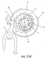
- FIG. 2(a) and 2(b) showing a print wheel and associated means for type selection.
- a print wheel 3 is mounted on a print wheel shaft 1 rotatable in the direction of arrow A.
- the print wheel 3 has a number of types (characters, numerals etc.) on its outer circumference, and on its side it is equipped with ratchet teeth 3b, each corresponding to one of the types 3a, and a reset claw 3c extending outside of the path of rotation of the ratchet teeth 3b.
- a print wheel spring 2 is part of a clutch system used for either engaging or disengaging the print wheel 3 with the print wheel shaft 1.
- the print wheel shaft 1 is provided with an indentation 1a cooperating with a protrusion 2a of the print wheel spring 2. If the protrusion 2a of the print wheel spring 2 engages the indentation 1a of the print wheel shaft 1 the print wheel 3 will be coupled to the print wheel shaft 1 so that with a rotation of the print wheel shaft 1 the print wheel 3 will be rotated until the print wheel spring 2 is disengaged from the indentation 1a of the print wheel shaft 1.
- a selection claw 4 is rotatably supported on a selection claw shaft 5.
- the print wheel shaft 1 and the print wheel 3 are rotated in the direction of arrow A.
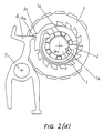
- a trigger coil 6 is energized, the selection claw 4 is rotated in the direction of arrow B to engage a ratchet tooth 3b and to stop the print wheel 3.
- the selection claw 4 is rotated in the direction of arrow C not to engage the ratchet teeth 3b and the reset claw 3c.
- the selection claw 4 When the printer begins operation in response to a print command starting from the standby condition shown in FIG. 2(a) the selection claw 4 is rotated in the direction of arrow C, the engagement of the end 4a of the selection claw 4 and the reset claw 3c of the print wheel is released, and then as the print wheel 3 immediately begins rotating in the direction of arrow A together with the print wheel shaft 1 the end 4a of the selection claw 4 rides over the reset claw 3c. The selection claw 4 then rotates back to the standby position and the type selection process begins.
- the print wheel 3 keeps rotating together with the print wheel shaft 1 until the trigger coil 6 is energized when the desired type 3a on the print wheel comes to the printing position. This causes the selection claw 4 to rotate in the direction of arrow B and to engage ratchet tooth 3b of the print wheel 3. As a result, the print wheel 3 stops. Since, however, the print wheel shaft 1 continues to rotate, the protrusion 2a of the print wheel spring 2 comes out of the indentation 1a of the print wheel shaft 1 thereby releasing the print wheel 3 from the print wheel shaft 1. This condition is shown in FIG. 2(b).
- the print wheel shaft 1 rotates until all of the desired types 3a of all print wheels 3 arranged in parallel on the print wheel shaft 1, are at the printing position. Then the printing process begins.
- the resetting process begins.
- the engagement of the selection claw 4 with the ratchet tooth 3b is released and the print wheel shaft 1 begins to rotate again. Due to the frictional force exerted by the spring force of the print wheel spring 2 the print wheel 3 follows the rotation of the print wheel shaft 1 in the direction of arrow A until the reset claw 3c of the print wheel 3 engages the selection claw end 4a. Then the print wheel 3 is stopped while the print wheel shaft 1 continues to rotate until the protrusion 2a of the print wheel spring 2 falls into the indentation 1a again, thus returning to the standby condition of FIG. 2(a).
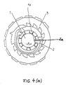
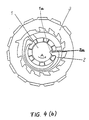
- FIG. 4(a) and FIG. 4(b) show conventional arrangements and correspond to FIG. 2(a) with the selection claw 4 and the trigger coil 6 being omitted.
- the shape of the indentation 1a is complementary to that of the protrusion 2a of the print wheel spring 2 with the leading face in the direction of arrow A extending substantially radially.
- the print wheel spring had to be made strong. Thereby the noise occurring when the print wheel spring enters into the indentation of the print wheel shaft is further increased.
- the strong print wheel spring additionally requires a larger drive force for the print wheel shaft which, in turn, increases the power consumption.
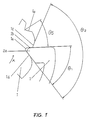
- Fig. 1 shows in detail the structure of the indentation of the print wheel shaft according to one embodiment of the invention.
- the figure shows the engaged condition of the protrusion 2a of the print wheel spring 2 and the indentation 1a of the print wheel shaft 1 by which the print wheel 3 is coupled to the print wheel shaft 1 during the selection process for both parts to be moved as a unit.
- the leading side of the indentation 1a comprises two slanted surfaces 1b and 1c.
- the surface 1b which is nearer to the center of the print wheel shaft 1 forms an angle ⁇ 1 with respect to the trailing surface 1d of the indentation 1a.
- the surface 1c which is nearer to the outer circumference of the print wheel shaft 1 forms an angle ⁇ 2 with respect to the trailing surface 1d.
- the angle ⁇ 2 is larger than the angle ⁇ 1.
- the print wheel shaft 1 has an auxiliary indentation 1e positioned at an angle ⁇ 5 ahead of the indentation 1a in the direction of rotation (A) of the print wheel shaft 1.
- the print wheel 3 tends to follow the rotation of the print wheel shaft 1 due to the frictional force generated by the spring force of the print wheel spring 2.
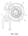
- the resetting process is fast and due to its inertia the print wheel 3 cannot follow the rotation of the print wheel shaft 1 by only the frictional force so that its phase gradually becomes delayed with respect to the print wheel shaft. Therefore, a relative rotation between the print wheel 3 and the print wheel shaft 1 occurs until the protrusion 2a of the print wheel spring 2 falls into the auxiliary indentation 1e of the print wheel shaft 1.
- the print wheel 3 being again coupled to the print wheel shaft 1 rotates until the reset claw 3c of the print wheel 3 engages the selection claw end 4a and then stops as shown in FIG. 2(d). Since, however, the print wheel shaft 1 continues to rotate, the protrusion 2a of the print wheel spring 2 comes out of the auxiliary indentation 1e and engages the indentation 1a again, thus returning to the standby condition.
- the protrusion of the print wheel spring 2 does not fall the full depth of the indentation 1a all at once, but rather, as shown in FIG. 2(e) it gradually slides down the slanted surface 1c of the indentation 1a near the circumference of the print wheel shaft 1 and then falls to the bottom of the indentation 1a, whereby its rate of fall is slowed and the impact lessened.
- a similar result is obtained with other values of angles ⁇ 1 and ⁇ 2 as long as the condition ⁇ 1 ⁇ ⁇ 2 is met.
- the printer since the depth of the indentation 1e is approximately one third that of the indentation 1a and the angle ⁇ 5 formed between the indentations 1e and 1a is approxi mately 30°, the printer was able to withstand printing speeds approximately twice those of the prior art.
- the shape, the angle ⁇ 5 and the number of auxiliary indentations 1e can be freely set, i.e. there may be more than one auxiliary indentation.
- FIG. 3 is a view corresponding to that of FIG. 1 for another embodiment of the present invention.
- the trailing slanted surface 2d i.e. the lower surface in FIG. 3
- the protrusion 2a forms an angle ⁇ 4 with the leading surface 2b of the protrusion 2a and an angle ⁇ 3 with the base 2c of the protrusion 2a, where ⁇ 4 > ⁇ 3.
- the leading surface 2b of the protrusion 2a is the surface sliding on the leading edge of the indentation 1a to have the protrusion 2a gradually entering the indentation 1a.
- the surface 2b of the second embodiment fulfills the function of the surface 1c of the first embodiment which, therefore, is not needed in the second embodiment.
- the ability of the print wheel to follow the print wheel shaft is improved, so that high-speed operation of the printer can be achieved with a smaller print wheel spring force resulting in low noise and low power consumption.
Landscapes
- Physics & Mathematics (AREA)
- Electromagnetism (AREA)
- Character Spaces And Line Spaces In Printers (AREA)
- Common Mechanisms (AREA)
Applications Claiming Priority (6)
| Application Number | Priority Date | Filing Date | Title |
|---|---|---|---|
| JP146482/89 | 1989-06-08 | ||
| JP14648289 | 1989-06-08 | ||
| JP25939589 | 1989-10-04 | ||
| JP259395/89 | 1989-10-04 | ||
| JP3033090A JPH0829610B2 (ja) | 1989-06-08 | 1990-02-09 | 小型プリンター |
| JP30330/90 | 1990-02-09 |
Publications (3)
| Publication Number | Publication Date |
|---|---|
| EP0401748A2 true EP0401748A2 (de) | 1990-12-12 |
| EP0401748A3 EP0401748A3 (de) | 1991-10-16 |
| EP0401748B1 EP0401748B1 (de) | 1994-04-20 |
Family
ID=27286931
Family Applications (1)
| Application Number | Title | Priority Date | Filing Date |
|---|---|---|---|
| EP90110613A Expired - Lifetime EP0401748B1 (de) | 1989-06-08 | 1990-06-05 | Kompakter Drucker der Druckradauswahl-Art |
Country Status (4)
| Country | Link |
|---|---|
| US (1) | US5158015A (de) |
| EP (1) | EP0401748B1 (de) |
| DE (1) | DE69008237T2 (de) |
| HK (1) | HK102797A (de) |
Families Citing this family (1)
| Publication number | Priority date | Publication date | Assignee | Title |
|---|---|---|---|---|
| JP2824545B2 (ja) * | 1992-12-31 | 1998-11-11 | ミネベア株式会社 | プリンタの字輪リセット機構 |
Family Cites Families (15)
| Publication number | Priority date | Publication date | Assignee | Title |
|---|---|---|---|---|
| US536448A (en) * | 1895-03-26 | Numbering machine | ||
| US1266807A (en) * | 1916-11-13 | 1918-05-21 | Henry E Hubbard | Resetting device. |
| US1951682A (en) * | 1930-07-14 | 1934-03-20 | Varren Alexander | Zero printing device for cash registers and calculating machines |
| US3269306A (en) * | 1964-02-18 | 1966-08-30 | Veeder Root Inc | Indicia wheel assembly |
| JPS5810237B2 (ja) * | 1978-08-19 | 1983-02-24 | キヤノン株式会社 | 活字輪選択方式の印字装置 |
| JPS5528810A (en) * | 1978-08-19 | 1980-02-29 | Canon Inc | Printing wheel selection type printing apparatus |
| US4314505A (en) * | 1978-10-13 | 1982-02-09 | Columbia Marking Tools, Inc. | Rotary wheel type marking head |
| JPS55138536U (de) * | 1979-03-23 | 1980-10-02 | ||
| JPS5634459A (en) * | 1979-08-31 | 1981-04-06 | Canon Inc | Printer |
| JPS5715970A (en) * | 1980-07-03 | 1982-01-27 | Seiko Epson Corp | Serial printer |
| JPS5831782A (ja) * | 1981-08-18 | 1983-02-24 | Seiko Epson Corp | 小型プリンタ |
| JPS5989186A (ja) * | 1982-11-15 | 1984-05-23 | Seiko Epson Corp | 小型プリンタ |
| JPS62152772A (ja) * | 1985-12-27 | 1987-07-07 | Alps Electric Co Ltd | プリンタ |
| US4760785A (en) * | 1985-12-25 | 1988-08-02 | Alps Electric Co., Ltd. | Printer with rotating hammers |
| JPH0445893Y2 (de) * | 1986-10-03 | 1992-10-28 |
-
1990
- 1990-06-05 EP EP90110613A patent/EP0401748B1/de not_active Expired - Lifetime
- 1990-06-05 DE DE69008237T patent/DE69008237T2/de not_active Expired - Lifetime
- 1990-06-07 US US07/534,691 patent/US5158015A/en not_active Expired - Fee Related
-
1997
- 1997-06-26 HK HK102797A patent/HK102797A/en not_active IP Right Cessation
Also Published As
| Publication number | Publication date |
|---|---|
| DE69008237T2 (de) | 1994-09-29 |
| US5158015A (en) | 1992-10-27 |
| EP0401748B1 (de) | 1994-04-20 |
| HK102797A (en) | 1997-08-15 |
| DE69008237D1 (de) | 1994-05-26 |
| EP0401748A3 (de) | 1991-10-16 |
Similar Documents
| Publication | Publication Date | Title |
|---|---|---|
| EP0519115B1 (de) | Abklappbarer Aussenrückblickspiegel | |
| US4090410A (en) | Paper feeding mechanism | |
| US4573813A (en) | Ribbon lift device for a printer | |
| EP0401748A2 (de) | Kompakter Drucker der Druckradauswahl-Art | |
| EP0590823B1 (de) | Papiermanipulationssystem für Drucker | |
| JPH07108648B2 (ja) | 自動車用安全ベルト拘束システムのためのベルト引込装置 | |
| US4152982A (en) | Miniature printer | |
| JP2000038109A (ja) | シ―トベルトリトラクタ用のブロッキング機構 | |
| JP3539857B2 (ja) | 間欠送り機構 | |
| US5628041A (en) | Film supplying device and method | |
| US5531132A (en) | Cam apparatus using an electromagnet and gears for decelerating a motor | |
| US3982256A (en) | Rotary shutter blade mechanism for cameras | |
| EP1398540B1 (de) | Vorrichtung zur Steuerung der Drehbewegung eines Nockens | |
| EP1441336B1 (de) | Plattenlaufwerk | |
| JP2001305605A (ja) | カメラ用フォーカルプレンシャッタ | |
| JPH0829610B2 (ja) | 小型プリンター | |
| JPH0111473Y2 (de) | ||
| US4420267A (en) | Serial printer | |
| JPS5928524Y2 (ja) | 検出機構 | |
| JPS5815174Y2 (ja) | 印字装置 | |
| JP2002142894A (ja) | リクライニング装置 | |
| JPH05263897A (ja) | カム機構 | |
| JP2004238840A (ja) | ステアリングロック装置 | |
| JP2002298486A (ja) | ディスクドライブ装置 | |
| JPH0135801Y2 (de) |
Legal Events
| Date | Code | Title | Description |
|---|---|---|---|
| PUAI | Public reference made under article 153(3) epc to a published international application that has entered the european phase |
Free format text: ORIGINAL CODE: 0009012 |
|
| AK | Designated contracting states |
Kind code of ref document: A2 Designated state(s): DE FR GB |
|
| PUAL | Search report despatched |
Free format text: ORIGINAL CODE: 0009013 |
|
| AK | Designated contracting states |
Kind code of ref document: A3 Designated state(s): DE FR GB |
|
| 17P | Request for examination filed |
Effective date: 19911126 |
|
| 17Q | First examination report despatched |
Effective date: 19930705 |
|
| GRAA | (expected) grant |
Free format text: ORIGINAL CODE: 0009210 |
|
| AK | Designated contracting states |
Kind code of ref document: B1 Designated state(s): DE FR GB |
|
| REF | Corresponds to: |
Ref document number: 69008237 Country of ref document: DE Date of ref document: 19940526 |
|
| ET | Fr: translation filed | ||
| PLBE | No opposition filed within time limit |
Free format text: ORIGINAL CODE: 0009261 |
|
| STAA | Information on the status of an ep patent application or granted ep patent |
Free format text: STATUS: NO OPPOSITION FILED WITHIN TIME LIMIT |
|
| 26N | No opposition filed | ||
| REG | Reference to a national code |
Ref country code: GB Ref legal event code: IF02 |
|
| PGFP | Annual fee paid to national office [announced via postgrant information from national office to epo] |
Ref country code: DE Payment date: 20090529 Year of fee payment: 20 Ref country code: GB Payment date: 20090603 Year of fee payment: 20 |
|
| REG | Reference to a national code |
Ref country code: GB Ref legal event code: PE20 Expiry date: 20100604 |
|
| PG25 | Lapsed in a contracting state [announced via postgrant information from national office to epo] |
Ref country code: GB Free format text: LAPSE BECAUSE OF EXPIRATION OF PROTECTION Effective date: 20100604 |
|
| PG25 | Lapsed in a contracting state [announced via postgrant information from national office to epo] |
Ref country code: DE Free format text: LAPSE BECAUSE OF EXPIRATION OF PROTECTION Effective date: 20100605 |
|
| PGFP | Annual fee paid to national office [announced via postgrant information from national office to epo] |
Ref country code: FR Payment date: 20090611 Year of fee payment: 20 |