EP0401564B1 - Vollreifen mit Bienenwabenstruktur mit einer Einzel-Membran an einer Seite - Google Patents
Vollreifen mit Bienenwabenstruktur mit einer Einzel-Membran an einer Seite Download PDFInfo
- Publication number
- EP0401564B1 EP0401564B1 EP90109189A EP90109189A EP0401564B1 EP 0401564 B1 EP0401564 B1 EP 0401564B1 EP 90109189 A EP90109189 A EP 90109189A EP 90109189 A EP90109189 A EP 90109189A EP 0401564 B1 EP0401564 B1 EP 0401564B1
- Authority
- EP
- European Patent Office
- Prior art keywords
- tire
- side web
- ribs
- swnpt
- web member
- Prior art date
- Legal status (The legal status is an assumption and is not a legal conclusion. Google has not performed a legal analysis and makes no representation as to the accuracy of the status listed.)
- Expired - Lifetime
Links
Images
Classifications
-
- B—PERFORMING OPERATIONS; TRANSPORTING
- B60—VEHICLES IN GENERAL
- B60C—VEHICLE TYRES; TYRE INFLATION; TYRE CHANGING; CONNECTING VALVES TO INFLATABLE ELASTIC BODIES IN GENERAL; DEVICES OR ARRANGEMENTS RELATED TO TYRES
- B60C7/00—Non-inflatable or solid tyres
- B60C7/10—Non-inflatable or solid tyres characterised by means for increasing resiliency
- B60C7/107—Non-inflatable or solid tyres characterised by means for increasing resiliency comprising lateral openings
-
- B—PERFORMING OPERATIONS; TRANSPORTING
- B60—VEHICLES IN GENERAL
- B60C—VEHICLE TYRES; TYRE INFLATION; TYRE CHANGING; CONNECTING VALVES TO INFLATABLE ELASTIC BODIES IN GENERAL; DEVICES OR ARRANGEMENTS RELATED TO TYRES
- B60C7/00—Non-inflatable or solid tyres
- B60C2007/005—Non-inflatable or solid tyres made by casting, e.g. of polyurethane
Definitions
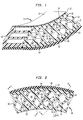
- This invention relates to a load-bearing side web non-pneumatic tire ("SWNPT" for brevity) having a generally quadrilateral silhouette (or toroidal, if the side web is capped to mimic the sidewall of a pneumatic tire, and the ribs are extended appropriately), viewed in cross-section in a vertical plane through the tire's (and wheel's) rotational spin axis.
- the cross-section is a generally rectangular silhouette, in another embodiment, one or both sides of the silhouette are either angulated or arcuate, and in yet another, a hybrid of the preceding rectangular and angulated or arcuate silhouettes.
- the tire comprises angularly oriented, oppositely directed planar rib members (referred to as "crossed ribs”) integrally connected by a single planar web member on one side of the tire ("side web” for brevity) which results in a non-expansible annular honeycomb sandwiched between inner and outer hoop members ("hoops") so that there is at least one row of passages having a cross-section generally resembling a quadrilateral.
- This and other rows of passages which may have the same, or different, cross-sectional shapes are formed as in a honeycomb, by the crossed ribs. All passages are open at the passages' open ends away from the side web (hence referred to as "one-side-open” honeycomb construction).
- non-expansible we refer to the diameter of a wheel fitted with a NPT, which diameter does not get larger when the wheel is rotated, due to the centrifugal forces generated during operation.
- the SWNPT of this invention is configured from an elastomeric synthetic resinous material having specified desirable properties, so as to provide optimum handling, cornering and load bearing characteristics for a given mass of resinous material.
- the term "handling” is used to define the general responsiveness of the vehicle to the expectations of the driver, but more specifically refers to the dynamics of the tires on the wheels of the vehicle, and in turn, the vehicle itself, due to lateral acceleration.
- elastomeric synthetic resinous material or “elastomer” we refer to a stiff, resilient, material having specific characteristics defined hereinafter.
- the elastomer may contain a minor proportion of a homopolymer or copolymer of a conjugated diene, preferably less than 10% by weight, and more preferably none.
- Rubber whether natural or synthetic (particularly, styrene-butadiene rubber, SBR), and blends thereof containing a major proportion by weight of a homopolymer or copolymer of a conjugated diene, whether vulcanized or not, is not an elastomer as defined herein, as it fails to meet the criteria set forth herebelow.
- the SWNPT provides handling and cornering comparable to that provided by the rectangular non-pneumatic tire ("RNPT") with a central web, disclosed in U.S. Patent Nos. 4,784,201 and 4,832,098.
- NPT non-pneumatic tire
- NPT allows itself to be deformed due to compression, and reverts to its original cylindrical shape while carrying its share of a load, typically as a tire mounted on a wheel rim of an automobile or a motorcycle.
- the dynamics of such deformation under load determines whether handling is satisfactory or not, such judgment generally being made with respect to a conventional pneumatic tire.
- a pneumatic tire has sidewalls which are smoothly and continuously blended into both side edges of its tread.
- inboard direction we refer to the direction in which the vehicle is being turned. With greater deflection, as in a tighter turn at higher speed, progressively more of the sidewall contacts the road. Under the severest conditions, the identifying lettering on the sidewall may be scuffed away by abrasion with the road surface. The side web, positioned on the outboard edge, counters such lateral deflection in the SWNPT.
- a RNPT specifically, exhibits marginally satisfactory handling when the RNPT is used under conditions which generate a high lateral acceleration. Under such dynamic conditions, the annular portion of the RNPT in contact with the road, is deflected laterally without benefit of any restraint by its sidewalls, because the RNPT doesn't have any. It will be recognized that the tread of a NPT comes to an abrupt end at each of its shoulders. Under severe cornering conditions, the outboard edges of the tread of the RNPT are severely abraded.
- the unique coaction of the structural elements of the SWNPT distributes forces, particularly those generated during turns, so that the forces are redirected by the presence of its outboard side web.
- Such redistribution of the forces unexpectedly provides the SWNPT with essentially the same or better deformation and load-bearing characteristics than those of a RNPT having the same mass.
- the ride provided by each belies the stiffness of the elastomeric material and the total lack of air trapped within the outboard side web provides a unique handling advantage over a pneumatic tire on a passenger automobile, yet with substantially no noticeable loss of the high degree of comfort provided by the pneumatic tire.
- the outboard sidewall of a pneumatic tire does not provide the same distribution or degree of stiffness provided by the side web.
- the unique one-side-open construction of the SWNPT effectively dissipates heat generated during continuous cycling between alternating compressive and tensile forces in play during operation.
- the SWNPT is ideal for a wide spectrum of wheeled vehicles in which (i) the susceptibility to puncture is obviated, (ii) increased wheel diameter is desirable, and (iii) progressive failure of the SWPT is required.
- This last condition applies to special-purpose vehicles such as a personnel carrier subject to sudden and serious damage, as for example a bullet, so that the effect of such damage is thus minimized.
- the overriding advantage of a pneumatic tire is the cushioning it provides, which cushioning, to date, as far as we know, has not been effectively mimiced with other NPTs.
- the disadvantage of the pneumatic tire is its susceptibility to being punctured.
- NPTs have been routinely used on vehicles where neither handling, nor cushioning the load is a prime consideration, as for example in fork lift trucks, carts, wheelbarrows, tricyles, and the like. Even so, the use of NPTs in such applications was less than satisfactory because prior art NPTs had undesirable handling characteristics. In addition, one could not provide a variable spring rate in a prior art NPT without changing either its design, that is, its structural configuration, or the materials of its construction. Apart from the lack of "good ride quality", solid tires, in particular those made from vulcanized rubber, were subject to high heat buildup and subsequent degradation after only constricted usage over a severely limited period.
- Fig 9 In European patent application 0159888 A2, published October 30, 1985, one embodiment (Fig 9) of a honeycomb structure is provided, but with dual planar side webs which enclose planar ribs adhesively secured so as to cross each other in the central circumferential plane, therefore not forming a honeycomb structure (requiring intersection of the ribs along the entire length of each rib) sandwiched between two sidewalls.
- the dual sidewalls provide desired support and rigidity, the structure is a pneumatic tire which cannot be cooled because air is enclosed in an air-tight annulus.
- the open construction of our SWNPT not only serves to cool it during operation, but permits superior handling in the corners.
- a cross-section of a NPT having a single side web may be formed having a configuration of oppositely directed crossed ribs connected to a single circumferential side web member (“side web”), on only one side of the NPT.
- the side web at its inner and outer radii, has its inner and outer peripheries respectively, connecting inner cylindrical (“inner hoop”), and outer cylindrical (“outer hoop”) members respectively of the SWNPT, at only one of the edges of the hoops, the connected edges being directly one above the other.
- Such an arrangement results in a SWNPT having the aforementioned characteristics, yet is capable of carrying a load of at least 226 kg (500 lbs), when mounted on the wheel of a vehicle operating at speeds up to 128 km/hr (80 miles/hr) for thousands of miles, without being much the worse for wear.
- the elastomer from which the annular resilient body of the SWNPT is formed has the following specific characteristics: Shore D hardness from about 40 to 65 (ASTM-D224), more preferably from about 45 to 55; a compression modulus (at 0.5 shape factor and 10% compression) in the range from about 21.000 kPa (3000 psi) to about 140.000 kPa (20,000 psi), more preferably from about 35.000 kPa (5000 psi) to 105.000 kPa (15,000 psi), which must not vary ⁇ 20% over the temperature range from 20°C to 70°C (ASTM-D695); a compression set of less than 60% (ASTM-D395B); a hysterisis (tan ⁇ ) of less than 0.25 measured at 70°C with a Rheometrics machine (ASTM-D2236), more preferably from about 0.05 to 0.15; and flex fatigue of more than 10,000 cycles at a maximum strain of 20% under normal
- Such materials are polyurethane, segmented copolyesters believed to be prepared by ester interchange of dimethyl terephthalate and isophthalate with polytetramethyleneether glycol and excess 1,4-butanediol, and block copolymers of nylon with rubber.
- the outer hoop may typically be provided with a rubber tread on the hoop's outer surface.
- the inner hoop is coaxial but not necessarily coextensive with the outer hoop, that is, the width (or length, measured in the axial direction) of the inner hoop may be the same as, or less than, that of the outer hoop.
- the silhouette in cross-sectional elevation will be different depending upon the embodiment of SWNPT chosen.
- the profile of the open ends of the ribs is of significance only in so far as the ribs together provide the necessary flow of air through their open ends, to keep the SWNPT cool, below its softening point, during operation, and, for the cosmetic appearance of the inboard profile, if such appearance is of importance.
- a center-line is drawn through the mid-point of the side web where it meets the inner hoop, to illustrate more clearly the shape of the side web as its thickness is varied.
- the shape and thickness of the side web are key elements in the determination of the handling characteristics to be built into the SWNPT.
- the terms "inboard” and “outboard” are used herein to indicate direction or positioning relative to the center-line of a wheeled vehicle on which the SWNPT is intended to be used. In an automobile, “outboard” refers to the outermost right and left hand sides (of a driver seated in driving position) of the automobile.
- the SWNPT (without the rubber cap and tread) is referred to as a "planar" SWNPT because a cross-sectional view of the side web shows it has parallel, vertical, inboard and outboard surfaces.
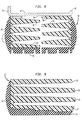
- the SWNPT (without the rubber cap and tread) is referred to as being "rectangular" (as for example, the right hand SWNPT of the two shown in Fig 8 ) when it presents a vertical inboard visual profile of a planar web, a vertical line (at the open ends of the ribs), and, first and second horizontal lines at the outer surfaces of the outer and inner hoops respectively, so that the general shape of the periphery of the cross-section of synthetic resinous material is a rectangle.
- the elevational visual profile of the ribs presents either an arcuate or vertical line at their open ends (an arcuate line is shown); outwardly inclined parallel lines at the inner and outer surfaces of the angled side web, these lines flaring outwardly at angle ⁇ from the radial plane (relative to the rotational spin axis) at the outer surface of the inner hoop; so that the shape of the periphery of the cross-section is generally of a trapezoid (a quadrilateral having two parallel sides).
- the elevational profile of the ribs presents an arcuate line at their open ends; the inboard face of the wedge-shaped side web flares ⁇ °, that is, inwardly at - ⁇ ° from the radially outer surface of the inner hoop to the radially inner surface of the outer hoop; and, outwardly at + ⁇ ° from the radially inner surface of the inner hoop to the radially outer surface of the outer hoop, so that the shape of the periphery of the cross-section is a trapezoid.
- any of the foregoing shapes of SWNPT is not adversely affected by the profile of the ribs at the SWNPT's open side.
- a profile may result with an open end which (a) flares outwardly at angle ⁇ in an angulated plane, or, (b) is arcuate (convex), so as to present a cosmetically pleasing symmetry of side profiles, the arcuate curve matching the convex outline of a foraminous rubber cap used to simulate a sidewall of a conventional pneumatic tire, the cap being perforated to cool the SWNPT during operation.
- the hoops are circular bands, much wider (that is, longer, in the axial direction) than they are thick (measured in the radial direction).
- the inner surface of the inner hoop is securely mounted on the rim of a wheel, so that the SWNPT, with a tread, may be used much the same way as a RNPT, or, a conventional pneumatic tire.
- the inner hoop is bonded to the rim, either by the adhesive strength of the polyurethane, or with an additional adhesive, so that mechanical fastening of the SWNPT to the rim is unnecessary.
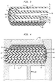
- the outer hoop 18 is spaced apart from the inner hoop 22 by a plurality of circumferentially spaced-apart oppositely directed and crossed planar first and second ribs, 26 and 30 respectively; and, a single side web 32, all of which are formed as a unitary construction.
- the single side web connects the inner and outer hoops at their outboard ends, that is, along the circumferential outer edges of the SWNPT, so that, if there were no ribs, the shape would be that of a U channel (lying on its one side) formed into a circle, the inner flange being substantially the same width, or narrower than the outer.
- the ribs extend as first and second sets of ribs, on the inboard side of the single side web, the first set angled in the range from about 15° to 75° to the radial planes which intersect the ribs in one direction, the second set angled in the same range but in the opposite direction.
- the ribs are oppositely directed at an angle in the range from about 30° to 60° so that they form a honeycomb structure with longitudinal passages open at one end, but closed on the other side by the single side web, so that passages 44 or 45 in at least one row of the honeycomb structure are longitudinal cells having a cross-section shaped substantially like a quadrilateral. Still other passages 46 and 47 near the inner and outer hoops respectively are more circular than quadrilateral.
- the unitary structure of the SWNPT is mounted on wheel rim 12 and configured so that the web and rib members provide a load-carrying structure with continuous deformation due to compression of the SWNPT as it rotates during operation.
- the thickness of the side web, the ribs and the hoops are such that there is essentially no detectable expansion of the SWNPT during operation; but in addition to deformation without buckling, due to compression during normal operation, the SWNPT is configured to allow the ribs to buckle, either individually or severally, when the SWNPT runs over a sudden projection in the road's surface.
- the word "buckle” as used herein is defined as a relatively sudden and radical deformation as a result of compression loading that exceeds a certain critical load value (hereinafter referred to as P cr ).
- the ribs 26 and 30 of the first and second sets respectively are of equal length L (in the generally radial direction) and oppositely directed, but at the same angle, for convenience in the molding of the SWNPT.
- first ribs 26 must cross second ribs 30, resulting in "crossed" ribs for optimum stiffness and load-carrying ability.
- Less convenient to mold is an SWNPT in which both, the lengths L (measured from the inner to the outer hoops) and the angulation of the ribs may be different as long as they are oppositely directed.
- the ribs 26 have a thickness d s measured in a direction perpendicular to its width (or length measured along the axis).
- the ribs are preferably undercut at 34, as shown, where their ends meet the inner and outer hoops 22 and 18 respectively, to enhance flexibility of the connection, thus facilitating compression of the ribs 26 and 30 without bending as each portion of the circumference of the SWNPT contacts the ground while the vehicle on which the SWNPT is mounted travels over the ground.
- the planar side web 32 is positioned at the outboard axial ends of the inner and outer hoops 18 an 22, and connected at its (the web's) radially inner periphery 32b to the inner hoop 22, and at its radially outer periphery 32c to outer hoop 18, so that the edges of ribs 26 and 30 lie along the inboard face 32a of the planar side web 32.
- All the first ribs 26 are similarly connected, so that all ribs are angled at angle A (see Fig 2) in the same direction, but the angle A may be different from one rib to another.
- all the second ribs 30 are connected at their corresponding inner and outer ends to the inner and outer hoops respectively and the ribs' edges also lie along the face 32a of the web, so that all the ribs in each of the sets 26 and 30 are angled at substantially equal angles A in the range from about 15° to about 75° to radial planes which intersect the ribs at their inner ends, but in opposite directions.
- the SWNPT When the SWNPT is to be used as a tire for an automobile or truck, the SWNPT is provided with a rubber tread 20 secured to the outer circumferential surface of the outer hoop 18.
- the stiffening function of the web 32 in combination with the crossed ribs is more clearly evident in Fig 1.
- the web tends to prevent the ribs from deforming by being bent along L, but allows compressive deformation of the SWNPT in the area around the point of contact with the ground.
- the ribs prevent the web from buckling in the axial direction until P cr is reached, so that the web and crossed ribs cooperate to carry the load.
- Changing the angle A of the ribs effectively varies the spring rate without changing the dimensions of the structural components of the SWNPT, or the composition of the elastomer from which it is molded.
- the particular design of the essential deformability and buckling characteristics of the SWNPT which imbue it with the ability to mimic the ride and handling characteristics of a conventional pneumatic tire, may be varied not only by changing the dimensions of the ribs and web, and the dimensions and relative disposition of the ribs, but also by varying the radius of the undercuts 34 which preferably range from 1,27 mm (0.05 ⁇ ) to 12,7 mm (0.5 ⁇ ) on the acute angle junctions of the ribs with the inner and outer hoops; and, from 6,35 mm (0.25 ⁇ ) to 25,4 mm (1 ⁇ ) on the obtuse angle junctions of the ribs with the inner and outer hoops.
- each rib is of unequal lengths, and the side web is capped with cap 40.
- Fig 4 there is shown an elevational view of a mold, with portions broken away, of a wheel indicated generally by 10, including the SWNPT 16 of this invention, molded from polyurethane and mounted on wheel rim 12.
- the additional second ribs 30 which constitute a second set, so referred to because the first and second sets of ribs are integrally connected by the side web 32 having a thickness d w , which web also connects the outer and inner hoops 18 and 22.
- the term "integral” refers to the SWNPT being formed as a whole, and the term “unitary” describes the interaction of the component structural elements as a unit. The terms together emphasize the molding or casting of the inner and outer hoops, the web and the ribs as a single construction using the elastomer, and the coaction of these structural elements of the SWNPT to discharge its stated functions.
- the hoop spacing is D.
- the tread 20 and cap 40 are produced as a continuous extrudate. A measured length of this extrudate is cut and pre-positioned in the mold before pouring the elastomer into it.
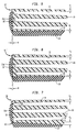
- FIG 5 there is schematically illustrated an angled SWNPT 16′ similar to that shown in Fig 3, having inner and outer hoops having thickness d i and d o respectively, first and second ribs 26 and 30 respectively, but an angled side web 32′, both surfaces of which are flared outward to improve cornering.
- the inner face 32a′ and the outer face are both angled at + ⁇ ° which ranges from 0°, when the side web is planar, to about 45°, the preferred range for an angled side web being in the range from about 1° to about 25°, depending of course upon the lateral forces the wheel is to endure, and the size of the wheel.
- Fig 6 there is schematically illustrated a wedge-shaped SWNPT 16 ⁇ similar to that shown in Fig 5, except that the side web 32 ⁇ is wedge-shaped.
- the inner face 32a ⁇ is angled inward at - ⁇ °, and the outer face of the wedge-shaped side web is angled outward at + ⁇ °, so that the angle of the wedge is 2 ⁇ °, when the inner face 32 ⁇ and outer face of the wedge flare at equal angles, and they may not be equal.
- Fig 7 there is schematically illustrated a planar SWNPT 16 similar to that shown in Fig 3, except that it has a tapered outer hoop 18′ to provide greater stiffness near its inboard end than is obtained with an outer hoop of substantially constant thickness.
- the inner surface of tread 20′ is tapered correspondingly.
- shoulder grooves 42 which also make pre-positioning the combination extrudate of tread and cap in the mold easier.
- Fig 9 there is schematically illustrated a planar SWNPT 16 similar to that shown in Fig 7, except that it has an outer hoop 18 ⁇ which is stepped, rather than tapered, to provide greater stiffness near its inboard end than is obtained with an outer hoop of substantially constant thickness.
- the inner surface of tread 20′ is stepped correspondingly.
- An annular body of a SWNPT for a luggage cart, fork lift, an automobile tire or spare tire, or insert for a pneumatic tire designed to have "run-flat" operation is formed with dimensions, dimensional relationships, and angular relationships which fall within the preferred ranges set forth in the following Table.
- Fig 8 schematically illustrates an angulated cross-sectional view of a pair of identical (twin) planar SWNPTs mounted in spaced apart mirror image relationship upon a wheel rim to provide a "wide footprint", yet permit the twin SWNPTs to generate a sufficient air-flow within the honeycomb structures to permit adequate cooling of the assembly.
- the outboard and inboard outer surfaces of each SWNPT is covered with a rubber cap and tread.
- the loading force on the SWNPT is approximately 363 kg (800 lb)
- it undergoes normal compressive deformation in a manner analogous with that obtained with the NPT of the parent application, during operation of a vehicle over a smooth road surface.
- the unloaded ribs are each 5.38 cm (2.12") long, while the loaded ribs are 5.05 cm (1.99") long.
- the space and weight objectives for a SWPNT which replaces a pnematic tire are best met if the total material volume (space occupied by the material of the SWNPT) divided by total projected volume (space between the outer surface of the outer hoop and the inner surface of the inner hoop) is between 20% and 60%.
- Another desirable characteristic of any tire is an overall spring rate which changes depending upon the type of surface against which the tire is loaded. Specifically, it is desirable that the spring rate be lower over a bump or obstructing article in the path of the SWNPT, than over a flat surface.
- the desirable ratio of spring rate over a flat surface divided by spring rate over a 1.27 cm (0.5") wide (high) cleat is between 1.4 and 6.0, preferably between 3 and 4.
- the annular body 16 may be adhered to the surface 24 of wheel rim 12 by being molded directly thereto in a conventional liquid molding process, with the outer surface 24 having been prepared in a known manner to receive and secure the elastomer used.
- the wheel rim 12 is provided with flanges 36 and 38 which cooperate with the mold to form the annular body 16 on surface 24.
- Any conventional method for molding polyurethane may be used to form the SWNPT, such as one described in aforementioned U.S. Patent No.4,832,098.
- the molding may conveniently be done with mold halves configured as shown in Fig 4 for a planar side web, and modified to provide "angled" and "wedge-shaped" SWNPTs respectively, it being evident that the positioning of the pins will be critical to provide the desired honeycomb structure. Equally evident is that the mold is to be filled with a fluent elastomer without producing pockets of air (voids) within the SWNPT. If desired, the cap 40 may be provided with vent passages 41 to facilitate cooling, and grooves in the tread for improved traction while the SWNPT while it is in operation.
- the following illustrative example 1 provides details of a molded polyurethane NPT.
- a SWNPT is conventionally molded in a mold having an inner mold ring by filling the mold with a reaction mixture of (a) toluenediisocyanate-poly(tetramethyleneether glycol (M.W. range 1000 - 2000, preferably about 1000) (TDI-PTMEG) prepolymer having a NCO number of 6.5, and, (b) methylene-bis-orthochloroaniline (MBOCA) curative the (a/b) weight ratio being 1/0.21.
- M.W. range 1000 toluenediisocyanate-poly(tetramethyleneether glycol
- M.W. range 1000 toluenediisocyanate-poly(tetramethyleneether glycol
- M.W. range 1000 toluenediisocyanate-poly(tetramethyleneether glycol
- M.W. range 1000 toluenediisocyanate-poly(t
- the liquid reaction mixture is poured into the mold with care being taken to ensure that all the air in the mold is displaced by the liquid.
- the SWNPT formed has ribs which are undercut in the acute angle at the inner hoop, and in the corresponding obtuse angle on the other side of the rib where it meets the outer hoop.
- a rubber tire tread having a thickness of about 1,78 cm (0.7 inch) is then adhered to the outer surface of the outer hoop 18 using a commercially available adhesive containing an aromatic diisocyanate and the resulting tire is fitted and adhered to a steel rim 12 using a polyurethane adhesive cured with an organic isocyanate curative.
- the SWNPT has the following dimensions: r i 25.4 cm (10") r o 30.48 cm (12") A 45° and 135° d i , d o 0.13 cm (0.05"), and 0.356 cm (0.14") D 3.18 cm (1.25”) r o /D 9.6 D/d w 12.5 L 4.49 cm (1.77”) L/d s 8.85 t i and t o 16.96 cm (6.68”), each
- the structure of the SWNPT of my invention is unique in that its honeycomb structure provides it stiffness but is deliberately designed to buckle under specified conditions to provide the characteristics essential to mimic a conventional pneumatic tire.
- This unique construction demands that the ribs be angulated and they be compressible, rather than bend under load.
- the resulting "open" structure, closed at one end by the side web not only provides the essential ride and handling characteristics but allows the SWNPT to dissipate heat during operation.
- the foregoing characteristics are lacking in any logical combination of the teachings of prior art references, each of which is conceptually so different that combining their teachings simply magnifies not only their conceptual differences but also the interaction of the structural elements which produce them.
Claims (21)
- Nicht-pneumatischer, um eine Achse drehbarer Reifen mit einem ringförmigen Körper (16) aus einem elastischen elastomeren Kunstharzmaterial, der im wesentlichen aufweist: ein generell zylindrisches Außenteil (18) am Außenumfang des Körpers, ein radial einwärts von dem Außenteil beabstandetes und mit diesem koaxiales generell zylindrisches Innenteil (22), mehrere axial verlaufende, umfangsmäßig beabstandete erste und zweite Rippenteile (26,30), die an ihren entsprechenden Innen- und Außenenden mit den zylindrischen Innen- und Außenteilen verbunden sind, wobei die Rippenteile unter Winkeln von ungefähr 15° bis 75° zu radialen Ebenen, die die Rippenteile an ihren Innenenden schneiden, einander entgegengesetzt ausgerichtet sind, und ein umlaufendes Seitenstegteil (32), dessen radial innere und äußere Umfangsbereiche mit den zylindrischen Innen- bzw. Außenteilen nur an einem einzigen Rand jedes dieser Teile verbunden sind, wobei ein verbundener Rand über dem anderen gelegen ist, wobei das Seitenstegteil an nur einer Seitenfläche sowohl mit den ersten als auch mit den zweiten Rippenteilen (26,30) verbunden ist,
dadurch gekennzeichnet,
daß der Reifen nur ein einziges Seitenstegteil (32) aufweist, daß das Seitenstegteil (32) einander entgegengesetzte Seitenflächen hat, die unter einem von 0° bis 30° betragenden Winkel ϑ an jeder Seite einer vertikal zur Drehachse des Reifens verlaufenden Ebene angeordnet sind, und daß die ersten Rippenteile (26) und die zweiten Rippenteile (30) mit dem zylindrischen Innenteil (22) und dem zylindrischen Außenteil (18) und dem Stegteil eine lasttragende Wabenstruktur bilden, die örtlich belastete Teile schafft, welche knickfähig sind. - Reifen nach Anspruch 1, bei dem der Winkel ϑ = 0° ist, derart, daß das Seitenstegteil (32) rechtwinklig zur Drehachse des Reifens verläuft und am auswärtigen Rand der axialen Enden der zylindrischen Teile (18,22) positioniert ist, und bei dem jedes der Rippenteile (26,30) axial von der einwärtigen Seitenfläche des Seitenstegteils absteht.
- Reifen nach Anspruch 1, bei dem die ersten (26) und die zweiten Rippenteile (30) an jedem Ende jeder Rippe mindestens in dem spitzen Winkel, in dem jede Rippe in das zylindrische Innenteil (22) und das zylindrische Außenteil (18) übergeht, hinterschnitten sind.
- Reifen nach Anspruch 1, bei dem der Seitensteg (32) unter dem Winkel ϑ auswärts von dem zylindrischen Innenteil (22) erweitert ist, derart, daß das Seitenstegteil von der Drehachse des Reifens weg geneigt ist und am auswärtigen Rand der axialen Enden der zylindrischen Teile (18,22) positioniert ist, um ein winkliges Seitenstegteil zu bilden, und bei dem jedes der Rippenteile (26,30) axial von der einwärtigen Seitenfläche des Seitenstegteils absteht.
- Reifen nach Anspruch 1, bei dem der Seitensteg (32) unter dem Winkel ϑ sowohl einwärts als auch auswärts von dem zylindrischen Innenteil (22) erweitert ist, derart, daß das Seitenstegteil keilförmig ist, und am auswärtigen Rand der axialen Enden der zylindrischen Teile (18,22) positioniert ist, und bei dem jedes der Rippenteile (26,30) axial von der einwärtigen Seitenfläche des Seitenstegteils absteht.
- Reifen nach Anspruch 1, bei dem die Rippenwinkel im wesentlichen gleich sind und im Bereich von 20° bis 60° liegen.
- Reifen nach Anspruch 3, bei dem sämtliche Rippen (26,30) gleiche Breite (Länge in axialer Richtung) aufweisen, derart, daß die einwärtigen Enden der Rippen in einer vertikalen Ebene abschließen, um dem nichtpneumatischen Reifen eine rechtwinklige Silhouette zu geben.
- Reifen nach Anspruch 3, bei dem die Rippen (26,30) in axialer Richtung ungleiche Länge aufweisen, derart, daß die einwärtigen Enden der Rippen mit einem bogenförmigen Profil abschließen.
- Reifen nach Anspruch 4, bei dem die Rippen (26, 30) in axialer Richtung ungleiche Länge aufweisen, derart, daß die einwärtigen Enden der Rippen in einer schrägen Ebene mit im wesentlichen dem gleichen Winkel wie demjenigen des winkligen Seitenstegteils abschließen.
- Reifen nach Anspruch 3, bei dem an der Außenfläche des zylindrischen Außenteils (18) eine umlaufende Lauffläche befestigt ist und an der inneren Umfangsfläche des zylindrischen Innenteils (22) eine Radfelge (12) befestigt ist.
- Reifen nach Anspruch 10, bei dem die Außenfläche des Seitenstegteils (32) mit einem generell konvexen Kappenteil (40) aus Gummi oder einem anderen Elastomer bedeckt ist.
- Reifen nach Anspruch 6, bei dem an der Außenfläche des zylindrischen Außenteils (18) eine umlaufende Lauffläche (20) befestigt ist, die einstückig mit einem generell konvexen Kappenteil (40) ausgebildet ist, welches die Außenfläche des Seitenstegteils (32) bedeckt.
- Reifen nach Anspruch 12, bei dem in die umlaufende Lauffläche (20) in dem Schulterbereich zwischen der Lauffläche (20) und dem konvexen Kappenteil (40) mindestens eine Umfangsnut (42) derart eingeschnitten ist, daß sie die Kühlung der Lauffläche, der Kappe und des Kunstharzmaterials erleichtert.
- Reifen nach Anspruch 12, bei dem das konvexe Kappenteil (40) mit an den Seitenstegen (32) endenden Durchlässen (41) durchsetzt ist, um die Kühlung des Reifens zu erleichtern.
- Reifen nach Anspruch 10, bei dem die auswärtige Fläche des Seitenstegteils (32) in der vertikalen Ebene rechtwinklig zu der Drehachse des Reifens angeordnet ist.
- Reifen nach Anspruch 10, bei dem die auswärtige Fläche des Seitenstegteils (32) unter einem Winkel ϑ im Bereich von 1° bis ungefähr 20° von der Vertikalen auswärts erweitert ist und einwärtige Enden der Rippen (26,30) nach außen hin erweitert sind und dabei Durchlässe mit offenen Enden bilden, wobei die Rippen derart enden, daß sie eine konvexe Silhouette schaffen.
- Reifen nach Anspruch 3, bei dem das Kunstharzmaterial einen geringen Gewichtsanteil eines Homopolymers oder Kopolymers eines konjugierten Dien enthält und die folgenden spezifischen Merkmale aufweist: Shore D-Härte im Bereich von ungefähr 40 bis 65 (ASTM-D224); Kompressionsmodul (bei einem Formfaktor von 0,5 und einer Kompression von 10%) im Bereich von ungefähr 21000 kPA (3000 psi) bis ungefähr 140000 kPA (20000 psi), wobei der Modul um ±20% über dem Temperaturbereich von 20° bis 70° (ASTM-D695) liegt; eine Verdichtungsverformung von weniger als 60% (ASTM-D395B); eine Hysterese (tan δ), gemessen bei 70° mit einer Rheometrie-Maschine (ASTM-D2236), im Bereich von ungefähr 0,05 bis 0,15; und eine Biegungsermüdung von mehr als 10000 Zyklen bei einer maximalen Belastung von 20% unter normalen Betriebsbedingungen ("Texus"-Biegetest, ASTM D3629-78).
- Reifen nach Anspruch 10, bei dem die Lauffläche (20), der ringförmige Körper (16) und die Radfelge (12) eine einstückige Radstruktur bilden.
- Reifen nach Anspruch 17, bei dem das Elastomer Polyurethan ist.
- Reifen nach Anspruch 19, bei dem das Polyurethan abgeleitet ist von einem Reaktionsgemisch aus(a) Tolouldiisocyanat/Polytetramethylenetherglycol-Prepolymer (Mol.Gew. 1000 bis ungefähr 2000) (TDI-PTMEG) mit ungefähr 5% bis ungefähr 7% NCO, und(b) einem Vulkanisationsmittel in ausreichender Menge, um die gewünschte Härte des Prepolymer zu erzeugen.
- Reifen nach Anspruch 20, bei dem das Vulkanisationsmittel aus der Gruppe Methylendianilin-NaCl-Komplex (MDA-NaCl, 50 Gewichtsprozent in Dioctylphthalat) und Methylenbisorthochloroanilin (MBOCA) ausgewählt ist, wobei das Gewichtsverhältnis von (a:b) im Bereich von 1/0,05 bis ungefähr 1/0,3 liegt.
Applications Claiming Priority (2)
| Application Number | Priority Date | Filing Date | Title |
|---|---|---|---|
| US07/364,344 US4945962A (en) | 1989-06-09 | 1989-06-09 | Honeycomb non-pneumatic tire with a single web on one side |
| US364344 | 1989-06-09 |
Publications (3)
| Publication Number | Publication Date |
|---|---|
| EP0401564A2 EP0401564A2 (de) | 1990-12-12 |
| EP0401564A3 EP0401564A3 (de) | 1991-06-12 |
| EP0401564B1 true EP0401564B1 (de) | 1994-03-02 |
Family
ID=23434086
Family Applications (1)
| Application Number | Title | Priority Date | Filing Date |
|---|---|---|---|
| EP90109189A Expired - Lifetime EP0401564B1 (de) | 1989-06-09 | 1990-05-16 | Vollreifen mit Bienenwabenstruktur mit einer Einzel-Membran an einer Seite |
Country Status (10)
| Country | Link |
|---|---|
| US (1) | US4945962A (de) |
| EP (1) | EP0401564B1 (de) |
| JP (1) | JPH0325004A (de) |
| AT (1) | ATE102125T1 (de) |
| BR (1) | BR9002719A (de) |
| CA (1) | CA2016660C (de) |
| DE (1) | DE69006917T2 (de) |
| DK (1) | DK0401564T3 (de) |
| ES (1) | ES2049859T3 (de) |
| MX (1) | MX163565B (de) |
Cited By (7)
| Publication number | Priority date | Publication date | Assignee | Title |
|---|---|---|---|---|
| WO2011011419A2 (en) * | 2009-07-20 | 2011-01-27 | Resilient Technologies, Llc | Tension-based non-pneumatic tire |
| US8104524B2 (en) | 2007-03-27 | 2012-01-31 | Resilient Technologies Llc | Tension-based non-pneumatic tire |
| US8109308B2 (en) | 2007-03-27 | 2012-02-07 | Resilient Technologies LLC. | Tension-based non-pneumatic tire |
| US8944125B2 (en) | 2009-07-20 | 2015-02-03 | Polaris Industries Inc. | Tension-based non-pneumatic tire |
| US9108470B2 (en) | 2008-09-29 | 2015-08-18 | Polaris Industries Inc. | Run-flat device |
| US9573422B2 (en) | 2012-03-15 | 2017-02-21 | Polaris Industries Inc. | Non-pneumatic tire |
| US9662939B2 (en) | 2009-07-28 | 2017-05-30 | Bridgestone Americas Tire Operations, Llc | Tension-based non-pneumatic tire |
Families Citing this family (103)
| Publication number | Priority date | Publication date | Assignee | Title |
|---|---|---|---|---|
| FR2652310A1 (fr) * | 1989-09-28 | 1991-03-29 | Michelin & Cie | Bandage deformable non pneumatique. |
| CA2043082A1 (en) * | 1991-02-27 | 1992-08-28 | James Edward Duddey | Non-pneumatic spare tire |
| US5460213A (en) * | 1992-03-18 | 1995-10-24 | Uniroyal Goodrich Licensing Services, Inc. | Multiple non-pneumatic tire and process for making it |
| US5265659A (en) * | 1992-03-18 | 1993-11-30 | Uniroyal Goodrich Licensing Services, Inc. | Non-pneumatic tire with ride-enhancing insert |
| BR9508617A (pt) * | 1994-08-19 | 1997-11-11 | Airboss Tyres Pty Ltd | Estrutura de aderência ao solo |
| KR100557510B1 (ko) * | 1994-08-19 | 2006-07-31 | 후쿠야마 러버 인더스트리얼 컴파니, 리미티드 | 타이어 |
| WO1996022891A1 (en) * | 1995-01-24 | 1996-08-01 | Airboss Tyres Pty. Ltd. | Tyre |
| EP0865368A4 (de) * | 1995-11-20 | 1999-02-17 | Airboss Tyres Pty Ltd | Zyklisch bewegbare bodenverbundstruktur |
| US5725701A (en) * | 1996-03-13 | 1998-03-10 | The Goodyear Tire & Rubber Company | Low pressure all terrain vehicle tire |
| US5879482A (en) * | 1996-03-15 | 1999-03-09 | Goodyear Tire & Rubber Company | Run-flat low-pressure all terrain vehicle (ATV) tire |
| US6068353A (en) * | 1998-07-10 | 2000-05-30 | Agtracks, Inc. | Track apparatus incorporating non-pneumatic wheels |
| US7418988B2 (en) * | 1999-12-10 | 2008-09-02 | Michelin Recherche Et Technique S.A. | Non-pneumatic tire |
| ATE378193T1 (de) * | 2001-08-24 | 2007-11-15 | Michelin Soc Tech | Nicht- pneumatischer reifen |
| US7013939B2 (en) * | 2001-08-24 | 2006-03-21 | Michelin Recherche Et Technique S.A. | Compliant wheel |
| US6681822B2 (en) | 2002-04-26 | 2004-01-27 | The Goodyear Tire & Rubber Company | Non-pneumatic spare tire |
| US7429801B2 (en) * | 2002-05-10 | 2008-09-30 | Michelin Richerche Et Technique S.A. | System and method for generating electric power from a rotating tire's mechanical energy |
| US7174936B2 (en) * | 2003-12-22 | 2007-02-13 | Caterpillar Inc | Solid suspended work machine tire |
| US20070029020A1 (en) * | 2004-06-09 | 2007-02-08 | Caterpillar Inc. | Solid suspended tire |
| WO2007057975A1 (ja) * | 2005-11-21 | 2007-05-24 | Space Inc. | 弾性構造体タイヤ |
| WO2008009042A1 (en) * | 2006-07-18 | 2008-01-24 | Crocodile Technology (Uk) Limited | Tyre construction |
| US11014407B2 (en) | 2007-03-27 | 2021-05-25 | Bridgestone Americas Tire Operations, Llc | Tension-based non-pneumatic tire |
| US20090058175A1 (en) * | 2007-09-05 | 2009-03-05 | Henkel Lin | Wheel for an in-line skate |
| US8056593B2 (en) * | 2007-10-26 | 2011-11-15 | Chemtura Corporation | Non-pneumatic tire |
| US8061398B2 (en) * | 2008-02-25 | 2011-11-22 | Chemtura Corporation | Non-pneumatic tire having angled tread groove wall |
| US20090110894A1 (en) * | 2007-10-26 | 2009-04-30 | Nybakken George H | Polyurethane elastomer articles from low free diphenylmethane diisocyanate prepolymers |
| US20090211677A1 (en) * | 2008-02-25 | 2009-08-27 | Palinkas Richard L | Modular tire assembly |
| US20090211681A1 (en) * | 2008-02-25 | 2009-08-27 | Palinkas Richard L | Tire and tire rim assembly |
| JP4506853B2 (ja) * | 2008-02-25 | 2010-07-21 | 横浜ゴム株式会社 | 非空気式タイヤ |
| US20110180194A1 (en) * | 2008-09-29 | 2011-07-28 | Resilient Technologies, Llc | Run-flat device |
| US20100078111A1 (en) * | 2008-09-29 | 2010-04-01 | Resillient Technologies, LLC | Run-flat device |
| JP5221306B2 (ja) * | 2008-11-28 | 2013-06-26 | 東洋ゴム工業株式会社 | 非空気圧タイヤ |
| US20110057402A1 (en) * | 2009-09-09 | 2011-03-10 | Keith Jewell | Multi-functional and convertible hand truck |
| US8479789B2 (en) * | 2009-09-15 | 2013-07-09 | Giles A. Hill, III | Self-pumping vent holes for cooling solid rubber tire and method of construction |
| US8662122B2 (en) | 2010-05-14 | 2014-03-04 | The Goodyear Tire & Rubber Company | System for non-pneumatic support of a vehicle |
| WO2011152813A1 (en) * | 2010-06-01 | 2011-12-08 | Cooper Tire & Rubber Company | Skew symmetric non-pneumatic tire |
| JP2013538963A (ja) * | 2010-06-25 | 2013-10-17 | バテル・メモリアル・インスティテュート | エレクトロアクティブポリマー(eap)をベースとした回転運動デバイス |
| US8555941B2 (en) * | 2010-08-12 | 2013-10-15 | The Boeing Company | Non-pneumatic survivable tire, cover and fabrication processes |
| US8567461B2 (en) * | 2010-08-12 | 2013-10-29 | The Boeing Company | Non-pneumatic survivable tire mounting system for conventional wheels |
| US9616713B2 (en) | 2010-08-30 | 2017-04-11 | The Goodyear Tire & Rubber Company | Non-pneumatic tire |
| CA2880961A1 (en) * | 2010-09-01 | 2012-03-08 | Michelin Recherche Et Technique S.A. | Spoke edge geometry for non-pneumatic tire |
| KR101301578B1 (ko) * | 2010-12-08 | 2013-08-29 | 한국타이어 주식회사 | 비공기압 타이어 |
| US8720504B2 (en) | 2011-06-17 | 2014-05-13 | The Goodyear Tire & Rubber Company | System for non-pneumatic support of a vehicle |
| KR101362120B1 (ko) * | 2011-11-22 | 2014-02-13 | 한국타이어 주식회사 | 에어리스 타이어 |
| JP5952079B2 (ja) * | 2012-05-15 | 2016-07-13 | コンビ株式会社 | ベビーカー用のタイヤ、ベビーカー用の車輪、ベビーカー |
| EP2890570A4 (de) * | 2012-08-30 | 2016-06-08 | Caterpillar Inc | Luftloser reifen |
| US9162407B2 (en) | 2012-09-07 | 2015-10-20 | Caterpillar Inc. | Systems and methods for forming non-pneumatic tires |
| US8636490B1 (en) | 2012-09-07 | 2014-01-28 | Caterpillar Inc. | Systems and methods for forming non-pneumatic tires |
| US9387637B2 (en) | 2012-09-07 | 2016-07-12 | Caterpillar Inc. | Systems and methods for forming non-pneumatic tires |
| US9266388B2 (en) | 2012-09-27 | 2016-02-23 | Mtd Products Inc | Non-pneumatic tire |
| JP2014080151A (ja) * | 2012-10-18 | 2014-05-08 | Bridgestone Corp | 非空気入りタイヤ |
| JP5972149B2 (ja) * | 2012-11-16 | 2016-08-17 | 東洋ゴム工業株式会社 | 非空気圧タイヤ |
| JP6051037B2 (ja) * | 2012-12-26 | 2016-12-21 | 株式会社ブリヂストン | 非空気入りタイヤ |
| JP6106428B2 (ja) * | 2012-12-26 | 2017-03-29 | 株式会社ブリヂストン | 非空気入りタイヤ |
| US9511631B2 (en) * | 2012-12-26 | 2016-12-06 | Bridgestone Corporation | Non-pneumatic tire |
| US9242509B2 (en) * | 2013-02-07 | 2016-01-26 | Alice Chang | Non pneumatic vehicle tires and pneumatic vehicle tires with tread patterns |
| KR101356326B1 (ko) * | 2013-02-28 | 2014-01-29 | 한국타이어 주식회사 | 각선재 구조의 구조 보강물을 가지는 비공기입 타이어 |
| JP6045401B2 (ja) * | 2013-03-05 | 2016-12-14 | 東洋ゴム工業株式会社 | 非空気圧タイヤ |
| USD731962S1 (en) | 2013-03-15 | 2015-06-16 | Caterpillar Inc. | Surface pattern for a tire |
| JP6291489B2 (ja) * | 2013-05-22 | 2018-03-14 | 住友ゴム工業株式会社 | エアレスタイヤ、及びその製造方法 |
| WO2014201368A1 (en) | 2013-06-15 | 2014-12-18 | Ronald Thompson | Annular ring and non-pneumatic tire |
| US20150034225A1 (en) * | 2013-07-30 | 2015-02-05 | Caterpillar Inc. | Reinforced non-pneumatic tire and system for molding reinforced non-pneumatic tire |
| EP3049257B1 (de) | 2013-09-24 | 2019-02-20 | Bridgestone Americas Tire Operations, LLC | Reifen mit einem toroidalen element |
| US20160288569A1 (en) * | 2013-11-22 | 2016-10-06 | Alain Parfondry | Polyurethane support for non-pneumatic tire |
| JP6751345B2 (ja) | 2013-12-24 | 2020-09-02 | ブリヂストン アメリカズ タイヤ オペレーションズ、 エルエルシー | 不定剛性を有するエアレスタイヤ構造 |
| US20150210025A1 (en) * | 2014-01-24 | 2015-07-30 | Caterpillar Inc. | System for molding non-pneumatic tires |
| RU2546360C1 (ru) * | 2014-03-03 | 2015-04-10 | Святослав Михайлович Сергеев | Колесо транспортного средства |
| US20150343840A1 (en) * | 2014-06-03 | 2015-12-03 | Caterpillar Inc. | Core of non-pneumatic tire and method of forming core |
| US9951757B2 (en) | 2014-07-31 | 2018-04-24 | Battelle Memorial Institute | Increased force generation in electroactive polymers |
| CN105882319A (zh) * | 2014-10-07 | 2016-08-24 | 邵再禹 | 一种蜂窝状免充气轮胎的设计方法 |
| US9849734B2 (en) | 2014-10-31 | 2017-12-26 | The Goodyear Tire & Rubber Company | Pneumatic tire with a three dimensional component |
| USD777655S1 (en) | 2014-12-02 | 2017-01-31 | Caterpillar Inc. | Urethane tire |
| JP2016113078A (ja) * | 2014-12-17 | 2016-06-23 | 株式会社ブリヂストン | 非空気入りタイヤ |
| WO2016099480A1 (en) | 2014-12-17 | 2016-06-23 | Compagnie Generale Des Etablissements Michelin | A non-pneumatic tire with integrated polymeric flexible wheel center mount |
| WO2016099476A1 (en) | 2014-12-17 | 2016-06-23 | Compagnie Generale Des Etablissements Michelin | Method and apparatus for molding non-pneumatic wheels |
| WO2016099474A1 (en) | 2014-12-17 | 2016-06-23 | Compagnie Generale Des Etablissements Michelin | Method and apparatus for molding non-pneumatic wheels |
| USD812552S1 (en) | 2014-12-18 | 2018-03-13 | Bridgestone Americas Tire Operations, Llc | Non-pneumatic tire |
| USD813152S1 (en) | 2014-12-18 | 2018-03-20 | Bridgestone Americas Tire Operations, Llc | Non-pneumatic tire |
| USD813151S1 (en) | 2014-12-18 | 2018-03-20 | Bridgestone Americas Tire Operations, Llc | Non-pneumatic tire |
| US10899169B2 (en) | 2015-01-27 | 2021-01-26 | Mtd Products Inc | Wheel assemblies with non-pneumatic tires |
| US20160214435A1 (en) | 2015-01-27 | 2016-07-28 | Mtd Products Inc | Wheel assemblies with non-pneumatic tires |
| USD792332S1 (en) | 2015-06-03 | 2017-07-18 | Mtd Products Inc | Non-pneumatic tire |
| EP3253591B1 (de) | 2015-02-04 | 2021-06-30 | Camso Inc. | Luftloser reifen und andere ringförmige vorrichtungen |
| USD767483S1 (en) | 2015-02-13 | 2016-09-27 | Caterpillar Inc. | Tire tread |
| USD784917S1 (en) | 2015-06-03 | 2017-04-25 | Mtd Products Inc | Non-pneumatic tire |
| USD773387S1 (en) | 2015-07-10 | 2016-12-06 | Caterpillar Inc. | Tire shear band |
| CN105109279B (zh) * | 2015-08-19 | 2017-11-07 | 张永汉 | 免充气轮胎 |
| US10071603B2 (en) | 2016-04-26 | 2018-09-11 | The Goodyear Tire & Rubber Company | Lightweight tire |
| CA2989339A1 (en) * | 2016-05-18 | 2017-11-23 | Lanxess Solutions Us Inc. | Non-pneumatic elastomeric tire with crossed spoke sidewalls |
| CN107336567A (zh) * | 2016-12-06 | 2017-11-10 | 安徽江淮汽车集团股份有限公司 | 无气轮胎及汽车 |
| CN106739819B (zh) * | 2016-12-21 | 2018-03-30 | 青岛双星轮胎工业有限公司 | 免充气轮胎 |
| CN106739827B (zh) * | 2016-12-21 | 2018-06-19 | 青岛双星轮胎工业有限公司 | 免充气轮胎 |
| FR3061674A1 (fr) * | 2017-01-12 | 2018-07-13 | Compagnie Generale Des Etablissements Michelin | Assemblage comprenant un tissu partiellement rompable et une structure porteuse |
| US10639226B1 (en) * | 2017-02-23 | 2020-05-05 | Koby Keyes Product Design, LLC | Mobility assistance apparatus |
| WO2018227276A1 (en) | 2017-06-15 | 2018-12-20 | Camso Inc. | Wheel comprising a non-pneumatic tire |
| KR101852305B1 (ko) * | 2017-08-24 | 2018-04-25 | 국방기술품질원 | 스포크 및 이를 이용한 비공기입 타이어 |
| EP3697629B1 (de) * | 2017-10-18 | 2021-12-01 | Compagnie Générale des Etablissements Michelin | Anordnung |
| WO2019089009A1 (en) * | 2017-10-31 | 2019-05-09 | Compagnie Generale Des Etablissements Michelin | Non-pneumatic tire carcass |
| US11654717B2 (en) * | 2017-12-21 | 2023-05-23 | Compagnie Generale Des Establissements Michelin | Reinforced annular support for a tire |
| CN108582612A (zh) * | 2018-04-24 | 2018-09-28 | 青岛金科模具有限公司 | 蜂窝式胎侧支撑的非充气轮胎离心浇注模具 |
| JP7143976B2 (ja) * | 2018-07-27 | 2022-09-29 | ブリヂストン アメリカズ タイヤ オペレーションズ、 エルエルシー | 非空気入りタイヤ用の再使用可能なリム |
| US11806959B2 (en) * | 2019-04-12 | 2023-11-07 | Ford Global Technologies, Llc | Tools for manufacturing non-pneumatic tires |
| JP7037522B2 (ja) * | 2019-07-11 | 2022-03-16 | Toyo Tire株式会社 | 非空気圧タイヤ用保護具及び車輪 |
| WO2021137956A1 (en) * | 2019-12-30 | 2021-07-08 | Bridgestone Americas Tire Operations, Llc | Non-pneumatic tire having molded sidewall cover |
Family Cites Families (8)
| Publication number | Priority date | Publication date | Assignee | Title |
|---|---|---|---|---|
| US2298142A (en) * | 1942-10-06 | Unitary spoke anx tueab | ||
| DE194492C (de) * | 1906-08-15 | 1908-01-21 | JEAN VINCENT FRANçOIS AMABLE YBERTY | Gummiradreifen mit quer zur längsrichtung des reifens versetzt angeordneten durchbohrungen |
| US1258573A (en) * | 1917-04-06 | 1918-03-05 | Samuel Johnstone | Automobile cushion-wheel. |
| GB601764A (en) * | 1944-10-26 | 1948-05-12 | Hugh Compton Lord | Cushioned tires |
| FR1278131A (fr) * | 1960-10-27 | 1961-12-08 | Roue pour véhicule notamment pour véhicules automobiles et procédés pour l'obtention de ladite roue | |
| US3980606A (en) * | 1975-02-24 | 1976-09-14 | The Firestone Tire & Rubber Company | Polyurethane elastomers having prolonged flex life and tires made therefrom |
| PL112739B1 (en) * | 1976-05-04 | 1980-10-31 | Polyair Maschinenbau Gmbh | Cellular tyre |
| US4832098A (en) * | 1984-04-16 | 1989-05-23 | The Uniroyal Goodrich Tire Company | Non-pneumatic tire with supporting and cushioning members |
-
1989
- 1989-06-09 US US07/364,344 patent/US4945962A/en not_active Expired - Lifetime
-
1990
- 1990-05-14 CA CA002016660A patent/CA2016660C/en not_active Expired - Fee Related
- 1990-05-16 DK DK90109189.2T patent/DK0401564T3/da active
- 1990-05-16 AT AT90109189T patent/ATE102125T1/de not_active IP Right Cessation
- 1990-05-16 ES ES90109189T patent/ES2049859T3/es not_active Expired - Lifetime
- 1990-05-16 EP EP90109189A patent/EP0401564B1/de not_active Expired - Lifetime
- 1990-05-16 DE DE69006917T patent/DE69006917T2/de not_active Expired - Fee Related
- 1990-06-08 JP JP2148835A patent/JPH0325004A/ja active Pending
- 1990-06-08 MX MX21086A patent/MX163565B/es unknown
- 1990-06-08 BR BR909002719A patent/BR9002719A/pt not_active IP Right Cessation
Cited By (9)
| Publication number | Priority date | Publication date | Assignee | Title |
|---|---|---|---|---|
| US8104524B2 (en) | 2007-03-27 | 2012-01-31 | Resilient Technologies Llc | Tension-based non-pneumatic tire |
| US8109308B2 (en) | 2007-03-27 | 2012-02-07 | Resilient Technologies LLC. | Tension-based non-pneumatic tire |
| US9108470B2 (en) | 2008-09-29 | 2015-08-18 | Polaris Industries Inc. | Run-flat device |
| WO2011011419A2 (en) * | 2009-07-20 | 2011-01-27 | Resilient Technologies, Llc | Tension-based non-pneumatic tire |
| WO2011011419A3 (en) * | 2009-07-20 | 2011-04-28 | Resilient Technologies, Llc | Tension-based non-pneumatic tire |
| US8176957B2 (en) | 2009-07-20 | 2012-05-15 | Resilient Technologies, Llc. | Tension-based non-pneumatic tire |
| US8944125B2 (en) | 2009-07-20 | 2015-02-03 | Polaris Industries Inc. | Tension-based non-pneumatic tire |
| US9662939B2 (en) | 2009-07-28 | 2017-05-30 | Bridgestone Americas Tire Operations, Llc | Tension-based non-pneumatic tire |
| US9573422B2 (en) | 2012-03-15 | 2017-02-21 | Polaris Industries Inc. | Non-pneumatic tire |
Also Published As
| Publication number | Publication date |
|---|---|
| DE69006917T2 (de) | 1994-06-09 |
| BR9002719A (pt) | 1991-08-20 |
| ES2049859T3 (es) | 1994-05-01 |
| CA2016660A1 (en) | 1990-12-09 |
| DE69006917D1 (de) | 1994-04-07 |
| EP0401564A3 (de) | 1991-06-12 |
| ATE102125T1 (de) | 1994-03-15 |
| EP0401564A2 (de) | 1990-12-12 |
| US4945962A (en) | 1990-08-07 |
| CA2016660C (en) | 1995-01-03 |
| JPH0325004A (ja) | 1991-02-01 |
| DK0401564T3 (da) | 1994-03-28 |
| MX163565B (es) | 1992-06-01 |
Similar Documents
| Publication | Publication Date | Title |
|---|---|---|
| EP0401564B1 (de) | Vollreifen mit Bienenwabenstruktur mit einer Einzel-Membran an einer Seite | |
| US4921029A (en) | Trapezoidal non-pneumatic tire with supporting and cushioning members | |
| EP0399383B1 (de) | Vollreifen in Trapezform mit Stütz- und Federungselementen | |
| US4832098A (en) | Non-pneumatic tire with supporting and cushioning members | |
| US5343916A (en) | Non-pneumatic spare tire | |
| US5460213A (en) | Multiple non-pneumatic tire and process for making it | |
| US5265659A (en) | Non-pneumatic tire with ride-enhancing insert | |
| US7650919B2 (en) | Non-pneumatic tire having web spokes | |
| US20020096237A1 (en) | Compliant rim and wheel and assembly | |
| US20120234444A1 (en) | Non-pneumatic tire with annular spoke reinforcing web | |
| JPH0359841B2 (de) | ||
| JPH01311902A (ja) | 非空気式タイヤ | |
| US6470935B1 (en) | Tire having inside walls | |
| US7287564B2 (en) | Tire safety support and rim and support assembly containing centering means and with facilitated mounting | |
| US6516845B2 (en) | Support device within a tire cavity to provide runflat capability | |
| US5685925A (en) | Filling for a puncture-proof pneumatic tire | |
| US7281553B1 (en) | Tire with compression-bearing hoop structure | |
| JPH01314603A (ja) | 非空気式タイヤ | |
| US6443201B1 (en) | Pneumatic tire with extended load carrying capacity | |
| EP1002667A1 (de) | asymmetrischer Luftreifen | |
| US6499521B2 (en) | Low aspect ratio pneumatic tire without sidewalls | |
| JP3428682B2 (ja) | 安全車輪及びその中子 | |
| JP3428680B2 (ja) | 安全車輪及びその中子 | |
| JPH08437B2 (ja) | タイヤの製造方法 |
Legal Events
| Date | Code | Title | Description |
|---|---|---|---|
| PUAI | Public reference made under article 153(3) epc to a published international application that has entered the european phase |
Free format text: ORIGINAL CODE: 0009012 |
|
| AK | Designated contracting states |
Kind code of ref document: A2 Designated state(s): AT BE CH DE DK ES FR GB GR IT LI LU NL SE |
|
| PUAL | Search report despatched |
Free format text: ORIGINAL CODE: 0009013 |
|
| AK | Designated contracting states |
Kind code of ref document: A3 Designated state(s): AT BE CH DE DK ES FR GB GR IT LI LU NL SE |
|
| 17P | Request for examination filed |
Effective date: 19910927 |
|
| 17Q | First examination report despatched |
Effective date: 19930513 |
|
| ITF | It: translation for a ep patent filed |
Owner name: DE DOMINICIS & MAYER S. |
|
| GRAA | (expected) grant |
Free format text: ORIGINAL CODE: 0009210 |
|
| AK | Designated contracting states |
Kind code of ref document: B1 Designated state(s): AT BE CH DE DK ES FR GB GR IT LI LU NL SE |
|
| REF | Corresponds to: |
Ref document number: 102125 Country of ref document: AT Date of ref document: 19940315 Kind code of ref document: T |
|
| REG | Reference to a national code |
Ref country code: DK Ref legal event code: T3 |
|
| REF | Corresponds to: |
Ref document number: 69006917 Country of ref document: DE Date of ref document: 19940407 |
|
| ET | Fr: translation filed | ||
| EPTA | Lu: last paid annual fee | ||
| REG | Reference to a national code |
Ref country code: GR Ref legal event code: FG4A Free format text: 3011962 |
|
| NLS | Nl: assignments of ep-patents |
Owner name: UNIROYAL GOODRICH LICENSING SERVICES, INC. TE GREE |
|
| REG | Reference to a national code |
Ref country code: CH Ref legal event code: PUE Owner name: UNIROYAL GOODRICH LICENSING SERVICES, INC. |
|
| PLBE | No opposition filed within time limit |
Free format text: ORIGINAL CODE: 0009261 |
|
| STAA | Information on the status of an ep patent application or granted ep patent |
Free format text: STATUS: NO OPPOSITION FILED WITHIN TIME LIMIT |
|
| REG | Reference to a national code |
Ref country code: FR Ref legal event code: TP |
|
| EAL | Se: european patent in force in sweden |
Ref document number: 90109189.2 |
|
| 26N | No opposition filed | ||
| ITPR | It: changes in ownership of a european patent |
Owner name: CESSIONE;UNIROYAL GOODRICH LICENSING SERVICES INC. |
|
| REG | Reference to a national code |
Ref country code: ES Ref legal event code: PC2A Owner name: UNIROYAL GOODRICH LICENSING SERVICES, INC. |
|
| PGFP | Annual fee paid to national office [announced via postgrant information from national office to epo] |
Ref country code: SE Payment date: 19980420 Year of fee payment: 9 |
|
| PGFP | Annual fee paid to national office [announced via postgrant information from national office to epo] |
Ref country code: DK Payment date: 19980422 Year of fee payment: 9 Ref country code: AT Payment date: 19980422 Year of fee payment: 9 |
|
| PGFP | Annual fee paid to national office [announced via postgrant information from national office to epo] |
Ref country code: NL Payment date: 19980430 Year of fee payment: 9 Ref country code: GR Payment date: 19980430 Year of fee payment: 9 |
|
| PGFP | Annual fee paid to national office [announced via postgrant information from national office to epo] |
Ref country code: CH Payment date: 19980506 Year of fee payment: 9 |
|
| PGFP | Annual fee paid to national office [announced via postgrant information from national office to epo] |
Ref country code: BE Payment date: 19980513 Year of fee payment: 9 |
|
| PGFP | Annual fee paid to national office [announced via postgrant information from national office to epo] |
Ref country code: ES Payment date: 19980520 Year of fee payment: 9 |
|
| PGFP | Annual fee paid to national office [announced via postgrant information from national office to epo] |
Ref country code: LU Payment date: 19980526 Year of fee payment: 9 |
|
| PG25 | Lapsed in a contracting state [announced via postgrant information from national office to epo] |
Ref country code: LU Free format text: LAPSE BECAUSE OF NON-PAYMENT OF DUE FEES Effective date: 19990516 Ref country code: AT Free format text: LAPSE BECAUSE OF NON-PAYMENT OF DUE FEES Effective date: 19990516 |
|
| PG25 | Lapsed in a contracting state [announced via postgrant information from national office to epo] |
Ref country code: SE Free format text: LAPSE BECAUSE OF NON-PAYMENT OF DUE FEES Effective date: 19990517 Ref country code: ES Free format text: LAPSE BECAUSE OF EXPIRATION OF PROTECTION Effective date: 19990517 |
|
| PG25 | Lapsed in a contracting state [announced via postgrant information from national office to epo] |
Ref country code: LI Free format text: LAPSE BECAUSE OF NON-PAYMENT OF DUE FEES Effective date: 19990531 Ref country code: GR Free format text: LAPSE BECAUSE OF NON-PAYMENT OF DUE FEES Effective date: 19990531 Ref country code: DK Free format text: LAPSE BECAUSE OF NON-PAYMENT OF DUE FEES Effective date: 19990531 Ref country code: CH Free format text: LAPSE BECAUSE OF NON-PAYMENT OF DUE FEES Effective date: 19990531 Ref country code: BE Free format text: LAPSE BECAUSE OF NON-PAYMENT OF DUE FEES Effective date: 19990531 |
|
| BERE | Be: lapsed |
Owner name: UNIROYAL GOODRICH LICENSING SERVICES INC. Effective date: 19990531 |
|
| PG25 | Lapsed in a contracting state [announced via postgrant information from national office to epo] |
Ref country code: NL Free format text: LAPSE BECAUSE OF NON-PAYMENT OF DUE FEES Effective date: 19991201 |
|
| REG | Reference to a national code |
Ref country code: CH Ref legal event code: PL |
|
| EUG | Se: european patent has lapsed |
Ref document number: 90109189.2 |
|
| NLV4 | Nl: lapsed or anulled due to non-payment of the annual fee |
Effective date: 19991201 |
|
| REG | Reference to a national code |
Ref country code: DK Ref legal event code: EBP |
|
| REG | Reference to a national code |
Ref country code: ES Ref legal event code: FD2A Effective date: 20010601 |
|
| REG | Reference to a national code |
Ref country code: GB Ref legal event code: IF02 |
|
| PGFP | Annual fee paid to national office [announced via postgrant information from national office to epo] |
Ref country code: GB Payment date: 20040512 Year of fee payment: 15 |
|
| PGFP | Annual fee paid to national office [announced via postgrant information from national office to epo] |
Ref country code: FR Payment date: 20040519 Year of fee payment: 15 |
|
| PGFP | Annual fee paid to national office [announced via postgrant information from national office to epo] |
Ref country code: DE Payment date: 20040630 Year of fee payment: 15 |
|
| PG25 | Lapsed in a contracting state [announced via postgrant information from national office to epo] |
Ref country code: IT Free format text: LAPSE BECAUSE OF NON-PAYMENT OF DUE FEES;WARNING: LAPSES OF ITALIAN PATENTS WITH EFFECTIVE DATE BEFORE 2007 MAY HAVE OCCURRED AT ANY TIME BEFORE 2007. THE CORRECT EFFECTIVE DATE MAY BE DIFFERENT FROM THE ONE RECORDED. Effective date: 20050516 Ref country code: GB Free format text: LAPSE BECAUSE OF NON-PAYMENT OF DUE FEES Effective date: 20050516 |
|
| PG25 | Lapsed in a contracting state [announced via postgrant information from national office to epo] |
Ref country code: DE Free format text: LAPSE BECAUSE OF NON-PAYMENT OF DUE FEES Effective date: 20051201 |
|
| GBPC | Gb: european patent ceased through non-payment of renewal fee |
Effective date: 20050516 |
|
| PG25 | Lapsed in a contracting state [announced via postgrant information from national office to epo] |
Ref country code: FR Free format text: LAPSE BECAUSE OF NON-PAYMENT OF DUE FEES Effective date: 20060131 |
|
| REG | Reference to a national code |
Ref country code: FR Ref legal event code: ST Effective date: 20060131 |