EP0400511A1 - Ringförmiges Kreissägeblatt und Ringkreissäge mit Sägeblattantrieb - Google Patents
Ringförmiges Kreissägeblatt und Ringkreissäge mit Sägeblattantrieb Download PDFInfo
- Publication number
- EP0400511A1 EP0400511A1 EP90110012A EP90110012A EP0400511A1 EP 0400511 A1 EP0400511 A1 EP 0400511A1 EP 90110012 A EP90110012 A EP 90110012A EP 90110012 A EP90110012 A EP 90110012A EP 0400511 A1 EP0400511 A1 EP 0400511A1
- Authority
- EP
- European Patent Office
- Prior art keywords
- saw blade
- annular
- drive
- saw
- flexible
- Prior art date
- Legal status (The legal status is an assumption and is not a legal conclusion. Google has not performed a legal analysis and makes no representation as to the accuracy of the status listed.)
- Granted
Links
- 239000000463 material Substances 0.000 claims abstract description 14
- 230000000694 effects Effects 0.000 claims abstract description 3
- 239000011343 solid material Substances 0.000 claims abstract 2
- 230000005540 biological transmission Effects 0.000 description 7
- 239000002184 metal Substances 0.000 description 2
- 238000004073 vulcanization Methods 0.000 description 2
- 229910000831 Steel Inorganic materials 0.000 description 1
- 230000008878 coupling Effects 0.000 description 1
- 238000010168 coupling process Methods 0.000 description 1
- 238000005859 coupling reaction Methods 0.000 description 1
- 229910003460 diamond Inorganic materials 0.000 description 1
- 239000010432 diamond Substances 0.000 description 1
- 238000006073 displacement reaction Methods 0.000 description 1
- 239000000428 dust Substances 0.000 description 1
- 230000002349 favourable effect Effects 0.000 description 1
- 238000007373 indentation Methods 0.000 description 1
- 230000004048 modification Effects 0.000 description 1
- 238000012986 modification Methods 0.000 description 1
- 230000035515 penetration Effects 0.000 description 1
- 230000002093 peripheral effect Effects 0.000 description 1
- 239000007787 solid Substances 0.000 description 1
- 239000010959 steel Substances 0.000 description 1
Images


Classifications
-
- B—PERFORMING OPERATIONS; TRANSPORTING
- B23—MACHINE TOOLS; METAL-WORKING NOT OTHERWISE PROVIDED FOR
- B23D—PLANING; SLOTTING; SHEARING; BROACHING; SAWING; FILING; SCRAPING; LIKE OPERATIONS FOR WORKING METAL BY REMOVING MATERIAL, NOT OTHERWISE PROVIDED FOR
- B23D47/00—Sawing machines or sawing devices working with circular saw blades, characterised only by constructional features of particular parts
- B23D47/12—Sawing machines or sawing devices working with circular saw blades, characterised only by constructional features of particular parts of drives for circular saw blades
- B23D47/123—Sawing machines or sawing devices working with circular saw blades, characterised only by constructional features of particular parts of drives for circular saw blades acting on the disc of the saw blade
-
- B—PERFORMING OPERATIONS; TRANSPORTING
- B23—MACHINE TOOLS; METAL-WORKING NOT OTHERWISE PROVIDED FOR
- B23D—PLANING; SLOTTING; SHEARING; BROACHING; SAWING; FILING; SCRAPING; LIKE OPERATIONS FOR WORKING METAL BY REMOVING MATERIAL, NOT OTHERWISE PROVIDED FOR
- B23D61/00—Tools for sawing machines or sawing devices; Clamping devices for these tools
- B23D61/02—Circular saw blades
- B23D61/025—Details of saw blade body
- B23D61/026—Composite body, e.g. laminated
Definitions
- the present invention relates to an annular saw blade with an outer periphery which is provided with cutting or tearing members, an inner periphery or inner edge and an annular web portion between the inner and outer peripheries.
- the invention also relates to an annular saw with driving means for driving the saw.
- a notable disadvantage is that the wear between the gear-wheel and the annular saw blade is very great, particularly when sawing concrete, metal and other heavy wear materials, since it is impossible to prevent saw dust from getting between the gear-wheel and the saw blade. Due to the wear, the saw blade is gradually displaced in the radial direction. As a result, the gear pitch of the saw blade changes so that it does not match the pitch of the driving gear-wheel. This tendency after a comparatively short period of time will cause a sudden disintegration of the saw blade. This is a problem not only as far as cost is concerned but also because it means that the risk of accidents is significantly increased.
- Friction-based transmissions for annular saw blades are described, for example, in the US-patents 3 221 783, 3 438 410, 3 930 310, and Re-27 716.
- these systems use one or more drive wheels which bear against one side of the web of the saw blade with opposite support from an opposing wheel bearing against the other side of the saw blade.
- it it it generally necessary to apply a high pressure between the drive wheel and the saw blade.
- heat is generated to such a high degree that the blade may be deformed, which can cause sudden disintegration of the blade.
- the bearings of the drive wheels may be damaged by the high pressure.
- annular saws Another problem which concerns all types of annular saws is that they give rise to an uncomfortably high noise level. While a conventional circular saw blade is kept firmly clamped on a driving shaft, an annular saw is rotated between one or more drive rollers and a plurality of support rollers. All these rollers together generate rattle and vibrations which cause a higher noise level than is experienced with conventional circular saws.
- the present invention provides an annular saw blade which is designed so that, when it is used in combination with an annular saw having suitably designed driving means, it will provide a drive substantially without slippage and with low power losses as a result of friction.
- the present invention combines the advantages of the gear wheel drive and the friction drive, which at the same time substantially avoids the drawbacks of those two systems.
- a saw blade with at least one annular driving surface of a flexible, solid polymeric material, preferably rubber, against which flexible driving surface a rotatable driving means is intended to be pressed to effect rotation of the saw blade about its center of rotation.
- the rotatable driving means is suitably provided with cogs, ridges, or other projections, which in principle provide a driving force having the same efficiency as a gear-wheel transmission.
- the resonance in the saw blade is significantly damped by means of the flexible material defining the driving surface, so that a remarkable attenuation of sound is achieved.
- the flexible material preferably rubber, may for example be located at the inner rim portion of the saw blade in order to permit the inner rim portion to co-operate with a drive wheel or a drive pulley provided inside the inner rim portion of the saw blade.
- a drive means having the features shown in the above-mentioned US-patent A 793 065.
- the only modification of the drive means which may have to be made is to replace the drive pulley with a drive pulley which has been provided with cogs or other projections in the wedge shaped groove of the drive pulley.
- the flexible material may be located on the web portion of the saw blade, suitably in a recess in the web portion.
- a drive means such as that shown in the above-mentioned US-Re-27 716, with the even drive wheel being replaced by a gear-wheel or by a wheel which has been provided with other projections around its periphery so that a secure grip with the flexible material is obtained with essentially the same character as a gear-wheel transmission.
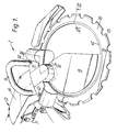
- a machine unit of a hydraulically driven annular saw 1 is generally designated 2.
- the machine unit 2 comprises a motor housing 6 with a hydraulic motor (not shown).
- the motor is provided with hydraulic conduits 3 and handles 4 and 5.
- the machine unit 2 also includes elements for holding an annular saw blade 8 in place in the machine unit and a transmission system for transmitting drive power of the motor to the saw blade 8.
- the machine unit 2 has a center disc 9 and a base plate 10.
- a cover 11 is mounted on the base plate 10 by means of screws 12, so that the cover 11 with the support elements for the saw blade 8 fitted in it can be removed when the saw blade 8 is to be fitted or replaced.
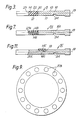
- the annular saw blade 8 has an inner rim portion 14 of rubber, an outer rim portion 15 provided with cutting elements in the shape of diamond tipped sectors, and a web portion 16 between the rim portions with a smooth underside 17 and a smooth topside 18.
- the sides 17 and 18 are parallel to each other and to a plane of symmetry 19 of the saw blade 8 (Fig. 3).
- the inner rim portion 14 of rubber is secured through vulcanization to the inner edge of the web portion 16 of the saw blade which consists of steel.
- the rubber portion 14 is completely straight according to this embodiment and has a thickness equal to that of the web portion 16 of the saw blade. Also the inner edge of the rubber portion 14 is completely straight.
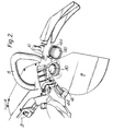
- a groove 24 is provided in the smooth underside 17 of the saw blade 8.
- a drive pulley 30 of the saw blade 8 is fitted mainly inside the annulus of the saw blade 8.
- the pulley 30 is arranged so as to be able to rotate around an axis of rotation 31, which is parallel to the axis of rotation of the saw blade 8, via a drive axle 32 (Fig. 4).
- transmission means (not shown) are provided for transmitting drive power of the motor to the drive pulley 30, together with a pair of lower running rollers 40 and 41 and a pair of upper running rollers 42 and 43 in the cover 11 (roller 43 is not shown).
- Each one of the lower running rollers 40 and 41 is provided with a flange 44 in a manner known per se.
- the flange 44 is accomodated in known manner in the groove 24 having an edge 45.
- the inner rim portion 14 of the saw blade 8 consists of rubber united with the inner edge 20 of the web portion 16 of the metal saw blade 8 through vulcanization.
- the rim portion 14 has the same thickness as the web portion 16 of the saw blade 8. The relative thickness is somewhat exaggerated in the drawings.
- the sides 21 and 22 of the rim portion 14 are parallel with and lie in the same planes as the sides 17 and 18 of the web portion 16.
- the inner edge 23 of the rubber portion 14 according to this embodiment is straight but could also be somewhat rounded.
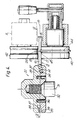
- the drive pulley consists of two halves 33 and 34, which abut each other in a dividing plane 35 and are clamped together by means of screws 36.
- the upper half of the drive pulley 30 has projections 37 alternating with valleys 38 in an annular rim portion facing the dividing plane 35, with the projections and valleys forming a circumferential wave pattern.
- the projections 37 and the valleys 38 follow smoothly upon each other but in other respects the annular rim portion has the feature of a gear-ring.
- the lower half 34 of the drive pulley is designed in an analogous manner but is rotated through an angle relative to the upper half corresponding to a half wave length, so that valleys and projections in the two halves will lie opposite each other.
- This groove 39 has a thickness which substantially corresponds to the thickness of the rubber rim portion 14 of the saw blade. Possibly, thegroove 39 may be somewhat narrower than the rim portion 14.
- the rubber rim portion 14 is provided in the groove 39 such that it will extend along a sector of the rim portion. In this way, the peripheral part of the rim portion 14 will be bent in a wave pattern between on one side the projection 37 and the valleys 38 in the first half 33, and on the other side the corresponding valleys, and projections 38′, 37′, respectively, in the second half 34.
- This is schematically illustrated in Fig. 6. In this mode there is achieved a very efficient coupling between the drive pulley 30 and the saw blade 8 without any greater pressure having to be applied to the rim portion 14 of the saw blade. As a result, the friction losses in driving the saw blade are very small.
- a saw blade 8A having a somewhat different design.
- the web portion 16A of this saw blade in its inner rim portion has a symmetrically projecting tongue 23A with smooth sides.
- the tongue 23A on both sides is covered by rubber layers 14A.
- the rubber layers 14A and the tongue 23A together have the same thickness as the web portion 16A.
- the rubber layers 14A on the saw blade 8A according to Fig. 7 can be used as drive surfaces in a groove in a drive pulley having a somewhat different design as Compared to the previous embodiment.
- Fig. 8 schematically illustrates this embodiment of the groove in the drive pulley, the upper and lower parts of which have been designated 33A and 34A.
- the projections 37A and valleys 38A in the one half 33A in this case are located opposite to corresponding projections 37A′ and valleys 38A′, respectively, in the other half 34A of the drive pulley.
- the layers 14A are alternately compressed and expanded, respectively through displacements of rubber at the passage through the groove. Also in this case there is achieved a very good grip between the drive pulley and the saw blade.
- the dimensions have been exaggerated in Fig. 8, as in Fig. 6, in order to make the mode of the operation clearer.
- FIG. 9 schematically illustrates one half of a drive pulley.
- the projections in this case consist of spherical segments 37B.
- the corresponding spherical segments in the other half of the drive pulley can be located between the spherical segments 37B shown in Fig. 9 (in this case there can be used, for example, a saw blade according to Fig. 3) or opposite to the spherical segments 37B (in this case there can be used, for example, a saw blade according to Fig. 7).
- a rubber layer 14C is provided in a groove 19 in the web portion 16C of the saw blade 8C.
- the inner rim portion 20C is somewhat bevelled.
- the drive pulley 30, according to the previous embodiments, in this case has been replaced by a drive roller 50, which operates between a pair of upper running rollers, which are designed in the same way as the running rollers 42 and 43 according to Fig. 4.
- a support roller 51 On the other side of the saw blade, opposite to the drive roller 50 there is a support roller 51, and opposite to the upper running rollers there may be provided a pair of lower running rollers, corresponding to the running rollers 40 and 41 according to Fig. 4.
- the latter ones, in this case are provided with a flange operating in the groove 24.
- the drive roller 50 is provided with a drive axle 55 and has a central portion 52 having cogs, ridges, or other projections alternating with valleys, grooves or similar indentations, which projections may be pressed into the rubber layer 14C in order to give a good grip between the drive wheel 50 and the saw blade 8C.
- the support roller 51 is provided with a flange 56 having a bevelled rotational surface which contacts and supports against the outer edge 20C of saw blade 8C in known manner. Rotational surfaces 57, 58 and 59 are provided which contact the underside of saw blade 8C.
- the drive pulleys or drive rollers are provided with projections intended to be pressed into the flexible material of the saw blade.
- This at least concerns an annular saw blade of the type where the flexible material has been located to the inner rim portion of the saw blade, as shown in Fig. 3.
- An annular saw blade of this type has been proven to work very efficiently together with a drive pulley having a wedge shaped groove with completely smooth sides.
- an annular saw blade of this type have given rise to considerably less noise than an annular saw blade without any rim portion of rubber.
- the invention therefore is not limited to be use of drive means, in the form of drive pulleys or drive rollers provided with projections as shown in the above-described embodiments.
Landscapes
- Engineering & Computer Science (AREA)
- Mechanical Engineering (AREA)
- Sawing (AREA)
- Polishing Bodies And Polishing Tools (AREA)
- Power Steering Mechanism (AREA)
- Road Repair (AREA)
- Seeds, Soups, And Other Foods (AREA)
- Processing Of Stones Or Stones Resemblance Materials (AREA)
- Nonmetal Cutting Devices (AREA)
Priority Applications (1)
| Application Number | Priority Date | Filing Date | Title |
|---|---|---|---|
| AT90110012T ATE95098T1 (de) | 1989-06-02 | 1990-05-26 | Ringfoermiges kreissaegeblatt und ringkreissaege mit saegeblattantrieb. |
Applications Claiming Priority (2)
| Application Number | Priority Date | Filing Date | Title |
|---|---|---|---|
| SE8902009A SE463858B (sv) | 1989-06-02 | 1989-06-02 | Ringformad saagklinga samt ringsaag med drivorgan foer saadan saagklinga |
| SE8902009 | 1989-06-02 |
Publications (2)
| Publication Number | Publication Date |
|---|---|
| EP0400511A1 true EP0400511A1 (de) | 1990-12-05 |
| EP0400511B1 EP0400511B1 (de) | 1993-09-29 |
Family
ID=20376167
Family Applications (1)
| Application Number | Title | Priority Date | Filing Date |
|---|---|---|---|
| EP90110012A Expired - Lifetime EP0400511B1 (de) | 1989-06-02 | 1990-05-26 | Ringförmiges Kreissägeblatt und Ringkreissäge mit Sägeblattantrieb |
Country Status (10)
| Country | Link |
|---|---|
| US (1) | US5009011A (de) |
| EP (1) | EP0400511B1 (de) |
| JP (1) | JPH0332515A (de) |
| AT (1) | ATE95098T1 (de) |
| AU (1) | AU619114B2 (de) |
| CA (1) | CA2018029A1 (de) |
| DE (1) | DE69003593T2 (de) |
| FI (1) | FI93323C (de) |
| NO (1) | NO174456C (de) |
| SE (1) | SE463858B (de) |
Cited By (4)
| Publication number | Priority date | Publication date | Assignee | Title |
|---|---|---|---|---|
| EP0879683A2 (de) * | 1997-05-23 | 1998-11-25 | Stalber S.r.l. | Geräuscharmes Steinschneidwerkzeug und dieses Werkzeug verwendende Maschine |
| EP2174738A1 (de) * | 2008-10-07 | 2010-04-14 | Stéphane Campeau | Ringkreissägevorrichtung |
| US20110167652A1 (en) * | 2010-01-13 | 2011-07-14 | Bernhard Brehm | Handsaw with annular saw blade and saw blade drive |
| WO2014146794A1 (de) * | 2013-03-21 | 2014-09-25 | Rfsdesign Ug (Haftungsbeschränkt) | Gerätekopf für ein werkzeuggerät, insbesondere für eine ringkreissäge oder einen winkelschleifer |
Families Citing this family (11)
| Publication number | Priority date | Publication date | Assignee | Title |
|---|---|---|---|---|
| DE4319949C2 (de) * | 1993-06-16 | 1995-04-13 | Schmid & Wezel Gmbh & Co | Rundmesserenthäuter und Rundmesser |
| SE509533C2 (sv) * | 1997-06-25 | 1999-02-08 | Electrolux Ab | Anordning vid kapmaskin |
| SE509549C2 (sv) * | 1997-06-25 | 1999-02-08 | Electrolux Ab | Drivhjul |
| USD406510S (en) * | 1997-06-25 | 1999-03-09 | Aktiebolaget Electrolux (Publ) | Cutting machine |
| SE524821C2 (sv) * | 2002-08-14 | 2004-10-05 | Electrolux Abp | Drivhjul för excentrisk drivning av en ringformad sågklinga i en kapmaskin |
| US7422292B2 (en) * | 2006-01-14 | 2008-09-09 | Husqvarna Professional Outdoor Products Inc. | Isolation system for movable saws, including a concrete saw |
| US9168188B2 (en) | 2007-11-13 | 2015-10-27 | Orthopediatrics Corporation | Cast removal system |
| US20090229133A1 (en) * | 2008-03-14 | 2009-09-17 | Stephane Campeau | Centerless saw device |
| JP5305229B2 (ja) * | 2008-12-17 | 2013-10-02 | 日立工機株式会社 | 切断工具 |
| US10434585B2 (en) * | 2016-12-29 | 2019-10-08 | Lee Yeong Industrial Co., Ltd. | Saw blade positioning mechanism for annular sawing machine |
| EP3760353A1 (de) | 2019-07-03 | 2021-01-06 | Hilti Aktiengesellschaft | Ringsägeblatt |
Citations (9)
| Publication number | Priority date | Publication date | Assignee | Title |
|---|---|---|---|---|
| SE70233C1 (de) * | 1929-03-28 | 1930-09-16 | ||
| US2690774A (en) * | 1951-02-02 | 1954-10-05 | Bert V Hoard | Wire-type power saw |
| DE1088408B (de) * | 1955-12-27 | 1960-09-01 | Wallram Hartmetall | Werkzeug zur Steinbearbeitung |
| US4026177A (en) * | 1976-07-21 | 1977-05-31 | Lokey Tool, Inc. | Rotary insulated saw blade |
| DE2740212A1 (de) * | 1976-09-08 | 1978-03-16 | Amada Co Ltd | Saegebandrolle |
| SU695813A1 (ru) * | 1978-03-06 | 1979-11-05 | Центральный научно-исследовательский институт механической обработки древесины | Узел резани круглопильного станка дл распиловки древесины |
| EP0060971A2 (de) * | 1981-03-20 | 1982-09-29 | Aktiebolag M.J.-Maskiner | Ringkreissägeblatt und Ringkreissäge |
| DE3236045A1 (de) * | 1982-09-29 | 1984-03-29 | Willy Bärhausen GmbH & Co KG, 6420 Lauterbach | Werkzeug fuer die steinbearbeitung |
| EP0264693A2 (de) * | 1986-10-22 | 1988-04-27 | Husqvarna Forest & Garden Aktiebolag | Kreissäge mit ringförmigem Sägeblatt |
Family Cites Families (3)
| Publication number | Priority date | Publication date | Assignee | Title |
|---|---|---|---|---|
| US4316328A (en) * | 1979-10-19 | 1982-02-23 | Micro-Precision, Inc. | Annular power tool |
| SU958085A2 (ru) * | 1981-01-06 | 1982-09-15 | Центральный научно-исследовательский институт механической обработки древесины | Узел резани круглопильного станка |
| SE460028B (sv) * | 1986-10-22 | 1989-09-04 | Electrolux Motor Ab | Ringformad cirkelsaagklinga |
-
1989
- 1989-06-02 SE SE8902009A patent/SE463858B/sv not_active IP Right Cessation
-
1990
- 1990-05-22 NO NO902241A patent/NO174456C/no unknown
- 1990-05-26 AT AT90110012T patent/ATE95098T1/de not_active IP Right Cessation
- 1990-05-26 DE DE90110012T patent/DE69003593T2/de not_active Expired - Fee Related
- 1990-05-26 EP EP90110012A patent/EP0400511B1/de not_active Expired - Lifetime
- 1990-06-01 FI FI902733A patent/FI93323C/fi not_active IP Right Cessation
- 1990-06-01 JP JP2141708A patent/JPH0332515A/ja active Pending
- 1990-06-01 CA CA002018029A patent/CA2018029A1/en not_active Abandoned
- 1990-06-01 AU AU56218/90A patent/AU619114B2/en not_active Ceased
- 1990-06-04 US US07/531,401 patent/US5009011A/en not_active Expired - Fee Related
Patent Citations (9)
| Publication number | Priority date | Publication date | Assignee | Title |
|---|---|---|---|---|
| SE70233C1 (de) * | 1929-03-28 | 1930-09-16 | ||
| US2690774A (en) * | 1951-02-02 | 1954-10-05 | Bert V Hoard | Wire-type power saw |
| DE1088408B (de) * | 1955-12-27 | 1960-09-01 | Wallram Hartmetall | Werkzeug zur Steinbearbeitung |
| US4026177A (en) * | 1976-07-21 | 1977-05-31 | Lokey Tool, Inc. | Rotary insulated saw blade |
| DE2740212A1 (de) * | 1976-09-08 | 1978-03-16 | Amada Co Ltd | Saegebandrolle |
| SU695813A1 (ru) * | 1978-03-06 | 1979-11-05 | Центральный научно-исследовательский институт механической обработки древесины | Узел резани круглопильного станка дл распиловки древесины |
| EP0060971A2 (de) * | 1981-03-20 | 1982-09-29 | Aktiebolag M.J.-Maskiner | Ringkreissägeblatt und Ringkreissäge |
| DE3236045A1 (de) * | 1982-09-29 | 1984-03-29 | Willy Bärhausen GmbH & Co KG, 6420 Lauterbach | Werkzeug fuer die steinbearbeitung |
| EP0264693A2 (de) * | 1986-10-22 | 1988-04-27 | Husqvarna Forest & Garden Aktiebolag | Kreissäge mit ringförmigem Sägeblatt |
Cited By (6)
| Publication number | Priority date | Publication date | Assignee | Title |
|---|---|---|---|---|
| EP0879683A2 (de) * | 1997-05-23 | 1998-11-25 | Stalber S.r.l. | Geräuscharmes Steinschneidwerkzeug und dieses Werkzeug verwendende Maschine |
| EP0879683A3 (de) * | 1997-05-23 | 2000-12-20 | Stalber S.r.l. | Geräuscharmes Steinschneidwerkzeug und dieses Werkzeug verwendende Maschine |
| EP2174738A1 (de) * | 2008-10-07 | 2010-04-14 | Stéphane Campeau | Ringkreissägevorrichtung |
| US20110167652A1 (en) * | 2010-01-13 | 2011-07-14 | Bernhard Brehm | Handsaw with annular saw blade and saw blade drive |
| EP2345498A1 (de) * | 2010-01-13 | 2011-07-20 | Maskin, Jerneviken | Handsäge mit ringförmigem Sägeblatt und Sägeblattbetrieb |
| WO2014146794A1 (de) * | 2013-03-21 | 2014-09-25 | Rfsdesign Ug (Haftungsbeschränkt) | Gerätekopf für ein werkzeuggerät, insbesondere für eine ringkreissäge oder einen winkelschleifer |
Also Published As
| Publication number | Publication date |
|---|---|
| NO902241L (no) | 1990-12-03 |
| NO174456C (no) | 1994-05-11 |
| SE8902009D0 (sv) | 1989-06-02 |
| FI93323B (fi) | 1994-12-15 |
| AU5621890A (en) | 1990-12-06 |
| AU619114B2 (en) | 1992-01-16 |
| SE8902009L (sv) | 1990-12-03 |
| ATE95098T1 (de) | 1993-10-15 |
| FI902733A0 (fi) | 1990-06-01 |
| SE463858B (sv) | 1991-02-04 |
| NO174456B (no) | 1994-01-31 |
| DE69003593D1 (de) | 1993-11-04 |
| US5009011A (en) | 1991-04-23 |
| FI93323C (fi) | 1995-03-27 |
| EP0400511B1 (de) | 1993-09-29 |
| DE69003593T2 (de) | 1994-01-20 |
| CA2018029A1 (en) | 1990-12-02 |
| NO902241D0 (no) | 1990-05-22 |
| JPH0332515A (ja) | 1991-02-13 |
Similar Documents
| Publication | Publication Date | Title |
|---|---|---|
| EP0400511B1 (de) | Ringförmiges Kreissägeblatt und Ringkreissäge mit Sägeblattantrieb | |
| US4516560A (en) | Abrasive cutting wheel and method of cutting abradable material | |
| US5460255A (en) | Universal segmented friction clutch facing | |
| US7740012B2 (en) | Working tool and machine for sawing and cutting | |
| CA1319825C (en) | Wear resistant abrasive cutting wheel | |
| EP0140421A1 (de) | Radial-Wellendichtung | |
| US4407178A (en) | Circular saw blades | |
| CA1227931A (en) | Abrasive cutting wheel | |
| US6058923A (en) | Saw blade | |
| EP0269631A1 (de) | Keilriemen und keilreimengetriebe. | |
| US4562761A (en) | Articulated saw | |
| US4464964A (en) | Articulated saw | |
| US4932509A (en) | Blade for liquid friction couplings | |
| JPS6327454B2 (de) | ||
| US4128031A (en) | Horizontal bandsaw machines | |
| US4967890A (en) | Clutch plate | |
| KR100414181B1 (ko) | 강도 및 냉각효과가 우수한 절삭톱날 | |
| CN217108113U (zh) | 摩擦挡片及传动机构 | |
| KR102073268B1 (ko) | 그리드 커플링 가공장치의 가공 유닛 | |
| KR200312627Y1 (ko) | 보강판 및 소음흡수판을 구비한 절삭톱날 | |
| KR101909302B1 (ko) | 표면 프로파일이 구비된 가요성 금속 링 및 이러한 링의 적층된 세트를 포함하는 구동 벨트 | |
| AU695973B2 (en) | Accessories and attachments for angle grinder | |
| JP4800751B2 (ja) | 回転装置 | |
| CA1229775A (en) | Articulated saw | |
| KR20220155734A (ko) | 원형 절삭 휠 |
Legal Events
| Date | Code | Title | Description |
|---|---|---|---|
| PUAI | Public reference made under article 153(3) epc to a published international application that has entered the european phase |
Free format text: ORIGINAL CODE: 0009012 |
|
| AK | Designated contracting states |
Kind code of ref document: A1 Designated state(s): AT BE CH DE DK ES FR GB IT LI NL |
|
| 17P | Request for examination filed |
Effective date: 19910502 |
|
| RAP1 | Party data changed (applicant data changed or rights of an application transferred) |
Owner name: AKTIEBOLAGET ELECTROLUX |
|
| 17Q | First examination report despatched |
Effective date: 19921216 |
|
| GRAA | (expected) grant |
Free format text: ORIGINAL CODE: 0009210 |
|
| AK | Designated contracting states |
Kind code of ref document: B1 Designated state(s): AT BE CH DE DK ES FR GB IT LI NL |
|
| PG25 | Lapsed in a contracting state [announced via postgrant information from national office to epo] |
Ref country code: NL Effective date: 19930929 Ref country code: LI Effective date: 19930929 Ref country code: ES Free format text: THE PATENT HAS BEEN ANNULLED BY A DECISION OF A NATIONAL AUTHORITY Effective date: 19930929 Ref country code: DK Effective date: 19930929 Ref country code: CH Effective date: 19930929 |
|
| REF | Corresponds to: |
Ref document number: 95098 Country of ref document: AT Date of ref document: 19931015 Kind code of ref document: T |
|
| REF | Corresponds to: |
Ref document number: 69003593 Country of ref document: DE Date of ref document: 19931104 |
|
| ITF | It: translation for a ep patent filed | ||
| ET | Fr: translation filed | ||
| REG | Reference to a national code |
Ref country code: CH Ref legal event code: PL |
|
| NLV1 | Nl: lapsed or annulled due to failure to fulfill the requirements of art. 29p and 29m of the patents act | ||
| PLBE | No opposition filed within time limit |
Free format text: ORIGINAL CODE: 0009261 |
|
| STAA | Information on the status of an ep patent application or granted ep patent |
Free format text: STATUS: NO OPPOSITION FILED WITHIN TIME LIMIT |
|
| 26N | No opposition filed | ||
| PGFP | Annual fee paid to national office [announced via postgrant information from national office to epo] |
Ref country code: GB Payment date: 19970519 Year of fee payment: 8 |
|
| PG25 | Lapsed in a contracting state [announced via postgrant information from national office to epo] |
Ref country code: GB Free format text: LAPSE BECAUSE OF NON-PAYMENT OF DUE FEES Effective date: 19980526 |
|
| PGFP | Annual fee paid to national office [announced via postgrant information from national office to epo] |
Ref country code: BE Payment date: 19980714 Year of fee payment: 9 |
|
| GBPC | Gb: european patent ceased through non-payment of renewal fee |
Effective date: 19980526 |
|
| PG25 | Lapsed in a contracting state [announced via postgrant information from national office to epo] |
Ref country code: BE Free format text: LAPSE BECAUSE OF NON-PAYMENT OF DUE FEES Effective date: 19990531 |
|
| BERE | Be: lapsed |
Owner name: ELECTROLUX A.B. Effective date: 19990531 |
|
| PGFP | Annual fee paid to national office [announced via postgrant information from national office to epo] |
Ref country code: AT Payment date: 20010514 Year of fee payment: 12 |
|
| PGFP | Annual fee paid to national office [announced via postgrant information from national office to epo] |
Ref country code: FR Payment date: 20010518 Year of fee payment: 12 |
|
| PG25 | Lapsed in a contracting state [announced via postgrant information from national office to epo] |
Ref country code: AT Free format text: LAPSE BECAUSE OF NON-PAYMENT OF DUE FEES Effective date: 20020526 |
|
| PG25 | Lapsed in a contracting state [announced via postgrant information from national office to epo] |
Ref country code: FR Free format text: LAPSE BECAUSE OF NON-PAYMENT OF DUE FEES Effective date: 20030131 |
|
| REG | Reference to a national code |
Ref country code: FR Ref legal event code: ST |
|
| PGFP | Annual fee paid to national office [announced via postgrant information from national office to epo] |
Ref country code: DE Payment date: 20050519 Year of fee payment: 16 |
|
| PG25 | Lapsed in a contracting state [announced via postgrant information from national office to epo] |
Ref country code: IT Free format text: LAPSE BECAUSE OF NON-PAYMENT OF DUE FEES;WARNING: LAPSES OF ITALIAN PATENTS WITH EFFECTIVE DATE BEFORE 2007 MAY HAVE OCCURRED AT ANY TIME BEFORE 2007. THE CORRECT EFFECTIVE DATE MAY BE DIFFERENT FROM THE ONE RECORDED. Effective date: 20050526 |
|
| PG25 | Lapsed in a contracting state [announced via postgrant information from national office to epo] |
Ref country code: DE Free format text: LAPSE BECAUSE OF NON-PAYMENT OF DUE FEES Effective date: 20061201 |