EP0399426A1 - Verfahren und Vorrichtung zur Herstellung von unverfälschten Wasserproben beim Niederbringen eines Brunnens durch Bohren - Google Patents
Verfahren und Vorrichtung zur Herstellung von unverfälschten Wasserproben beim Niederbringen eines Brunnens durch Bohren Download PDFInfo
- Publication number
- EP0399426A1 EP0399426A1 EP90109574A EP90109574A EP0399426A1 EP 0399426 A1 EP0399426 A1 EP 0399426A1 EP 90109574 A EP90109574 A EP 90109574A EP 90109574 A EP90109574 A EP 90109574A EP 0399426 A1 EP0399426 A1 EP 0399426A1
- Authority
- EP
- European Patent Office
- Prior art keywords
- tube
- perforation
- water
- insert
- filter
- Prior art date
- Legal status (The legal status is an assumption and is not a legal conclusion. Google has not performed a legal analysis and makes no representation as to the accuracy of the status listed.)
- Granted
Links
- XLYOFNOQVPJJNP-UHFFFAOYSA-N water Substances O XLYOFNOQVPJJNP-UHFFFAOYSA-N 0.000 title claims abstract description 43
- 238000005553 drilling Methods 0.000 title claims abstract description 19
- 238000000034 method Methods 0.000 title claims abstract description 16
- 239000004576 sand Substances 0.000 claims abstract description 23
- 239000012530 fluid Substances 0.000 claims abstract 2
- 239000007787 solid Substances 0.000 claims description 26
- 238000005070 sampling Methods 0.000 claims description 2
- 238000011010 flushing procedure Methods 0.000 description 4
- 238000009434 installation Methods 0.000 description 4
- 239000002689 soil Substances 0.000 description 4
- 238000005086 pumping Methods 0.000 description 3
- 238000004519 manufacturing process Methods 0.000 description 2
- 239000000126 substance Substances 0.000 description 2
- 239000000356 contaminant Substances 0.000 description 1
- 230000001419 dependent effect Effects 0.000 description 1
- 239000003673 groundwater Substances 0.000 description 1
- 230000000717 retained effect Effects 0.000 description 1
- 230000007704 transition Effects 0.000 description 1
Images


Classifications
-
- E—FIXED CONSTRUCTIONS
- E21—EARTH OR ROCK DRILLING; MINING
- E21B—EARTH OR ROCK DRILLING; OBTAINING OIL, GAS, WATER, SOLUBLE OR MELTABLE MATERIALS OR A SLURRY OF MINERALS FROM WELLS
- E21B49/00—Testing the nature of borehole walls; Formation testing; Methods or apparatus for obtaining samples of soil or well fluids, specially adapted to earth drilling or wells
- E21B49/08—Obtaining fluid samples or testing fluids, in boreholes or wells
- E21B49/084—Obtaining fluid samples or testing fluids, in boreholes or wells with means for conveying samples through pipe to surface
-
- E—FIXED CONSTRUCTIONS
- E21—EARTH OR ROCK DRILLING; MINING
- E21B—EARTH OR ROCK DRILLING; OBTAINING OIL, GAS, WATER, SOLUBLE OR MELTABLE MATERIALS OR A SLURRY OF MINERALS FROM WELLS
- E21B43/00—Methods or apparatus for obtaining oil, gas, water, soluble or meltable materials or a slurry of minerals from wells
- E21B43/02—Subsoil filtering
- E21B43/08—Screens or liners
- E21B43/082—Screens comprising porous materials, e.g. prepacked screens
-
- G—PHYSICS
- G01—MEASURING; TESTING
- G01N—INVESTIGATING OR ANALYSING MATERIALS BY DETERMINING THEIR CHEMICAL OR PHYSICAL PROPERTIES
- G01N1/00—Sampling; Preparing specimens for investigation
- G01N1/02—Devices for withdrawing samples
- G01N1/10—Devices for withdrawing samples in the liquid or fluent state
- G01N1/14—Suction devices, e.g. pumps; Ejector devices
Definitions
- the invention relates to a manufacturing method according to the preamble of claim 1.
- the invention also relates to an apparatus for carrying out this method.
- Such adulterations are generally based on parts of the borehole drilling, which has absorbed water from the surrounding mountains or from already drilled water-bearing horizons and therefore, among other things, adulterating substances in contaminated soils, e.g. B. Contains contaminants.
- the method according to the invention enables such falsifications of the sample water to be suppressed and thus the assessment of which water qualities can be expected from which samples.
- This is based essentially on the essentially hollow cylindrical filter placed in the annular space between the drill pipe and the borehole before each sample sand body through which the sample water is pumped out.
- This filter sand body holds solid parts from the flushing with its upper section, which surrounds a solid casing tube of the hollow rod, and thereby becomes clogged, whereby a natural ring seal is created against the water-bearing horizon in which the rod perforation tube is located. Therefore, the filter sand body described is incorporated by pumping the sample water out of the borehole over a certain period of time until the aforementioned ring seal is formed and clear water appears from the approached horizon. The filter sand is held back by the rods.
- the boom has a plurality of boom perforation pipes at a distance from the water-bearing layers, under each of which is arranged a catch device which can be blocked by the borehole butt, which is extended by lifting the boom and then holding back the filter sand attached, so that the hollow cylindrical filter sand body mentioned can be built.
- the invention has for its object to carry out the previously known method so that a change of linkage between the water samples is no longer necessary, but nevertheless genuine water samples are obtained.
- the drill pipe itself is used for pumping out the water samples through the hollow pipe trains, except for drilling the test hole.
- the hollow cylindrical filter sand plug described at the outset which is necessary for obtaining the unadulterated water samples, is destroyed with the borehole flushing as soon as the rod perforation tube is closed and further drilled. This makes it possible to stop the drilling in each water-bearing horizon approached from top to bottom as soon as the rod perforation tube has reached the leading horizon and now pour the filter sand body without a special collecting device, which further simplifies the drill rod.
- the invention has the advantage that, according to the method proposed by her, unadulterated water samples can be obtained when the well is being drilled, which is possible without pulling the rod. This will make the drilling work simplified and significantly accelerated.
- wells of initially unknown depths can be raised until one reaches a water-bearing horizon which supplies water of suitable quality and quantity.
- the method according to the invention is therefore particularly suitable as an examination method for unknown soils with possibly unknown loads caused by contaminating substances.
- the drilling device shown in FIG. 1, which at the same time serves to obtain unadulterated water samples, is generally designated (1) and drills a borehole (2).
- An annular gap remains between the borehole joint (3) and the drill pipe (4). It arises from the difference in diameter of the drilling tool (5) and the drill pipe (4).
- the drilling tool (5) is arranged directly below a perforated drill pipe (6).
- the perforations (7) are arranged in a plurality of horizontal and vertical rows and penetrate the tubular jacket essentially radially.
- An essentially hollow cylindrical filter sand body (8) fills the annular space between the perforated drill pipe (6) and the borehole joint (3) up to the bottom of the borehole. It extends up to the last solid casing rod train (9) of the drill pipe.
- the perforation tube insert (10) and the perforation drill pipe (6) are connected to each other via locking bolts (11) and a holder (12), so that the exact fit of the perforation tube insert (10) in the rod perforation tube (6) is ensured. Openings (13) are provided in the perforation insert (10), in the example shown in FIG. 5, longitudinal slots approximately 0.5 mm wide, so that the correspondingly coarser filter sand of the filter sand body (8) is effectively retained.
- the safety device (15) is shown, with the aid of which the perforated pipe insert (10) can be removed again in order to insert the solid casing pipe insert shown in the other figures there when the Drilling work should be started.
- the safety device (15) has draw bolts (16) which engage in the recesses (17) in the inner wall (18) of the perforation tube insert (10) and via which the safety device (15) is able to hold the entire perforation tube insert (10). through the drill to lift the linkage (4) out.
- the function of the mounting bolts is explained in more detail with reference to FIG. 7.
- closure (22) which serves to prevent the water to be examined from inadvertently flowing into the rod interior (23) bypassing the filter sand body.
- the closure (22) acts like a check valve.
- Fig. 6 shows a safety gear with draw bolts (16) and installation bolts (19).
- the two bolts (16, 19) are loaded via springs (20). They protrude from the corresponding bores or cutouts if they are not prevented from doing so by the inner wall of the perforated tube insert (10) or the solid jacket tube insert.
- At least the draw bolts (16) are provided with bevels (29) on the side facing the deepest hole (28) in order to insert the safety device (15) into the perforated tube insert (10). or to ensure the solid casing insert (30), initially retracting and only then snapping into the assigned recess (17) in the inner wall (18) of the perforated tubular insert (10) or the solid casing insert (30) as soon as this is necessary.
- Fig. 7 shows the lower area of the drill pipe (4), the solid casing insert (30) being pushed directly into the area of the drill pipe (6) directly above the safety device (15).
- the perforations (7) in the perforated drill pipe (6) are then closed via this tube insert (30).
- the solid jacket tube insert (30) has reached its prescribed position.
- the safety device (30) presses on the insert edge (26) according to FIG. 3 via the installation bolts (19).
- the solid casing insert (30) is brought into the required end position in any case.
- the safety device (15) is lowered into the insert, with the installation bolts retracted or retracting (19). As soon as the tension bolts (16) snap into the tension groove (25), the installation bolts (19), as can be seen in FIG. 1, are out of function. The safety device (15) can be withdrawn, taking the solid casing insert (30) with it.
- the limitation (31) on the inner wall (32) prevents the safety device (15) from being pushed in too far, for example into the solid casing insert (30).
- the edges (33, 34) of the solid casing insert (30) are beveled, as can be seen from FIGS. 7 and 8.
- the bevels are expediently designed to be reversed when working with a device in which the solid casing pipe inserts (30) are fixed in the area of the solid casing string train (9) lying above them during the water withdrawal.
- the retrieval of the solid casing tube inserts (30) or the perforation tube inserts (10) is not necessary, the perforation insert (10) and the perforation rod train (6) also forming a unit.
- Fig. 2 is the linkage
- the upper end of the perforation tube (6) is screwed to the subsequent solid jacket rod train (9) at (35).
- a snap ring (36) is used to hold a filter tube (37), preferably made of plastic, in the perforation rod train (6).
- the filter tube (37) is supported on an inner annular collar (38) of the perforation rod train (6). Its inside diameter corresponds to the inside diameter of the hollow rod.
- the arrangement described has the advantage that the perforations (40) of the perforation rod train, which weaken the tubular casing (39), need only have a relatively small free opening and do not weaken it excessively.
- the filter tube insert (37) on the other hand, has the relatively large open area of the fine slots required for the filter edge and a relatively low stability, which, however, is increased by the combination with the perforation tube to such an extent that the forces which occur can be absorbed.
- Fig. 2 shows the inserted solid casing insert (30), which carries an O-ring seal (41, 42) at its upper and lower ends. This ensures that the borehole flushing cannot pass through perforations (40) of the rod perforation tube (6) as long as the drilling operation continues.
- FIG 3 shows the perforated tube insert (10) used, which also has an O-ring seal (43, 44) at the upper and lower ends.
- the perforations (45) correspond to the size and free area of the filter sand.
- the inserted solid jacket tube insert (30) permits the opening of the check valve body (46) under load by the valve spring (47) as soon as the borehole flushing presses on the valve body (46) through the drill pipe.
Landscapes
- Life Sciences & Earth Sciences (AREA)
- Engineering & Computer Science (AREA)
- Geology (AREA)
- Mining & Mineral Resources (AREA)
- Physics & Mathematics (AREA)
- Chemical & Material Sciences (AREA)
- Environmental & Geological Engineering (AREA)
- Fluid Mechanics (AREA)
- General Life Sciences & Earth Sciences (AREA)
- Geochemistry & Mineralogy (AREA)
- General Health & Medical Sciences (AREA)
- Health & Medical Sciences (AREA)
- Analytical Chemistry (AREA)
- Biochemistry (AREA)
- Hydrology & Water Resources (AREA)
- General Physics & Mathematics (AREA)
- Immunology (AREA)
- Pathology (AREA)
- Dispersion Chemistry (AREA)
- Sampling And Sample Adjustment (AREA)
- Earth Drilling (AREA)
- Investigation Of Foundation Soil And Reinforcement Of Foundation Soil By Compacting Or Drainage (AREA)
- Optical Measuring Cells (AREA)
- Drilling And Exploitation, And Mining Machines And Methods (AREA)
- Centrifugal Separators (AREA)
- Separation Using Semi-Permeable Membranes (AREA)
- Perforating, Stamping-Out Or Severing By Means Other Than Cutting (AREA)
- Filtration Of Liquid (AREA)
Abstract
Description
- Die Erfindung betrifft ein Herstellungsverfahren gemäß dem Oberbegriff des Anspruches 1. Außerdem betrifft die Erfindung eine Vorrichtung zur Durchführung dieses Verfahrens.
- Nach dem erfindungsgemäßen Verfahren werden z. B. aus kontaminierten Böden Wasserprcben gewonnen, welche aus einem wasserführenden Horizont stammen, der mit der Bohrung angefahren worden ist, wobei aber die Proben von den Verfälschungen frei sind, die durch das Abpumpen der Proben durch das Hohlgestänge und das Bohrloch in die Wasserproben gelangen können, sobald diese den wasserführenden Horizont verlassen haben. Solche Verfälschungen beruhen in der Regel auf Teilen der Bohrlochspülung, welche aus dem umgebenden Gebirge bzw. aus bereits durchteuften wasserführenden Horizonten zusitzende Wässer aufgenommen hat und deswegen unter anderem bei kontaminierten Böden ihrerseits verfälschende Substanzen, z. B. Kontaminationen enthält. Das erfindungsgemäße Verfahren erlaubt die Unterdrückung solcher Verfälschungen des Probenwassers und damit die Beurteilung, aus welchen Proben welche Wasserqualitäten zu erwarten sind.
- Das beruht im wesentlichen auf dem vor jeder Probe in den Ringraum zwischen dem Bohrgestänge und dem Bohrloch eingebrachten, im wesentlichen hohlzylindrischen Filter sandkörper, durch den das Probewasser abgepumpt wird. Dieser Filtersandkörper hält nämlich mit seinem oberen, ein Vollmantelrohr des Hohlgestänges umgebenden Abschnitt Feststoffteile aus der Spülung fest und setzt sich dadurch zu, wodurch eine natürlich Ringdichtung gegen den wasserführenden Horizont entsteht, in dem das Gestängeperforationsrohr steht. Deshalb wird nach dem erfindungsgemäßen Verfahren der beschriebene Filtersandkörper beim Abpumpen des Probenwassers aus dem Bohrloch über eine gewisse Zeitspanne eingearbeitet, bis die erwähnte Ringdichtung entstanden ist und klares Wasser aus dem angefahrenen Horizont erscheint. Der Filtersand wird dabei von dem Gestänge zurückgehalten.
- Dieses Verfahren ist seinem Grundsatz nach bereits bekannt (PCT-Anmeldung WO 82/0 43 52). Wenn nach diesem Verfahren mehrere übereinanderliegende Grundwasserhorizonte untersucht werden sollen, hat das Gestänge im Abstand der wasserführenden Schichten eine Vielzahl von Gestängeperforationsrohren unter denen jeweils ein mit dem Bohrlochstoß versperrbare Auffangvorrichtung angeordnet ist, welche durch das Anheben des Gestänges ausgefahren wird und dann den angebrachten Filtersand zurückhält, so daß die erwähnten hohlzylindrischen Filtersandkörper aufgebaut werden können.
- Dieses vorbekannte Verfahren läßt sich in der Regel nur mit zwei Gestängen ausführen, die wechselseitig oder nacheinander in das Bohrloch eingefahren werden müssen. Das zum Probeziehen erforderliche Gestänge ist relativ kompliziert aufgebaut und setzt die Kenntnis der Abstände der wasserführenden Horizonte voraus, um die Perforationsgestängerohre in den richtigen Abständen für die Herstellung der Filtersandkörper anordnen zu können. Im allgemeinen wird man daher nach diesem Verfahren zunächst die Brunnenbohrung ganz oder zum Teil auffahren und danach erst das mit den Perforationsgestängerohren versehene Gestänge einfahren. Das ist aus organisatorischen Gründen an sich schon nachteilig und liefert leicht falsche Ergebnisse, wenn man im unbekannten Boden zu bohren hat und nicht weiß, wie tief die Bohrung abgeteuft werden muß, um auf einen wasserführenden Horizont zu treffen, der Wasser geeigneter Qualität und Menge liefert.
- Der Erfindung liegt die Aufgabe zugrunde, das vorbekannte Verfahren so zu führen, daß ein Gestängewechsel zwischen den Wasserproben nicht mehr erforderlich ist, jedoch gleichwohl unverfälschte Wasserproben gewonnen werden.
- Diese Aufgabe löst die Erfindung mit den Merkmalen des Anspruches 1. Weitere Merkmale der Erfindung sind Gegenstand der Unteransprüche.
- Gemäß der Erfindung wird das Bohrgestänge selbst außer zum Auffahren der Probebohrung zum Abpumpen der Wasserproben durch die hohlen Gestängezüge verwendet. Es hat sich nämlich überraschend herausgestellt, daß der eingangs beschriebene hohlzylindrische Filtersandstopfen, der für die Gewinnung der unverfälschten Wasserproben erforderlich ist, mit der Bohrlochspülung zerstört wird, sobald das Gestängeperforationsrohr verschlossen und weitergebohrt wird. Dadurch ist es möglich, in jedem von oben nach unten nacheinander angefahrenen wasserführenden Horizont die Bohrung anzuhalten, sobald das Gestängeperforationsrohr in den führenden Horizont angelangt ist und nunmehr den Filtersandkörper ohne eine besondere Auffangvorrichtung einzuschütten, was das Bohrgestänge weiter vereinfacht.
- Die Erfindung hat den Vorteil, daß nach dem von ihr vorgeschlagenen Verfahren unverfälschte Wasserproben während des Niederbringens der Brunnenbohrung bedarfsweise gewonnen werden können, was ohne Ziehen des Gestänges möglich ist. Dadurch werden die Bohrarbeiten vereinfacht und wesentlich beschleunigt. Man kann nach dem erfindungsgemäßen Verfahren Brunnen von zunächst unbekannter Teufe auffahren bis man an einen wasserführenden Horizont gelangt ist, der Wasser geeigneter Qualität und Menge liefert. Das erfindungsgemäße Verfahren eignet sich daher besonders gut als Untersuchungsverfahren für unbekannte Böden mit gegebenenfalls nicht bekannten Belastungen durch kontaminierend wirkende Substanzen.
- Die Einzelheiten, weiteren Merkmale und andere Vorteile der Erfindung ergeben sich aus der nachfolgenden Beschreibung zweier Ausführungsformen einer Vorrichtung zur Durchführung des beschriebenen Verfahrens gemäß der Erfindung.
- Es zeigen:
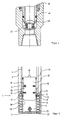
- Fig. 1 schematische und teilweise im Längsschnitt unter Fortlassung aller für das Verständnis der Erfindung nicht erforderlichen Einzelheiten eine erste Ausführungsform der Erfindung im Längsschnitt,
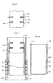
- Fig. 2 in gegenüber der Darstellung der Fig. 1 vergrößerter Wiedergabe ein Perforationsgestängerohr gemäß der Erfindung für die Durchführung des Bohrbetriebes,
- Fig. 3 in der Fig. 2 entsprechender Darstellung des Perforationsgestängerohr für die Durchführung einer Wasserprobennahme,
- Fig. 4 den Gegenstand der Fig. 3 in vergrößerter Darstellung zur Wiedergabe einer Einzelheit des Perforationsgestängerohres,
- Fig. 5 eine andere Ausführungsform der Erfindung, im wesentlichen der Fig. 1 entsprechenden Darstellung, jedoch unter Fortlassung des Bohrwerkzeuges,
- Fig. 6 eine Fangvorrichtung für den Gegenstand der Fig. 5,
- Fig. 7 die im Bohrgestänge befindliche Fangvorrichtung nach Fig. 2,
- Fig. 8 einen Vollmantelrohreinsatz gemäß der Erfindung für die Ausführungsform nach den Fig. 1 bis 3.
- Die aus Fig. 1 ersichtliche Bohreinrichtung, die gleichzeitig zur Gewinnung unverfälschter Wasserproben dient, ist allgemein mit (1) bezeichnet und fährt ein Bohrloch (2) auf. Zwischen dem Bohrlochstoß (3) und dem Bohrgestänge (4) verbleibt ein Ringspalt. Er entsteht durch die Durchmesserdifferenz des Bohrwerkzeuges (5) und des Bohrgestänges (4). Das Bohrwerkzeug (5) ist unmittelbar unterhalb eines Perforationsgestängerohres (6) angeordnet.
- Die Perforationen (7) sind in einer Vielzahl von horizontalen und vertikalen Reihen angeordnet und durchsetzen den Rohrmantel im wesentlichen radial. Ein im wesentlichen hyhlzylindrischer Filtersandkörper (8) füllt den Ringraum zwischen dem Perforationsgestängerohr (6) und dem Bohrlochstoß (3) bis zur Sohle des Bohrloches aus. Er reicht bis zu dem letzten Vollmantelgestängezug (9) des Bohrgestänges.
- In der Ausführungsform nach den Fig. 5 bis 8 liegt auf der Innenseite des Perforationsgestängerohres (6) ein Perforationsrohreinsatz (10), der den Filtersand zurückhält, so daß nur vom Filtersand freies Wasser in das Innere des Bohrgestänges (4) eindringen kann, sobald eine nicht dargestellte Pumpe das Wasser zutage hebt.
- Der Perforationsrohreinsatz (10) und das Perforationsgestängerohr (6) sind über Rastbolzen (11) und einer Halterung (12) miteinander verbunden, so daß der e naue Sitz des Perforationsrohreinsatzes (10) im Gestängeperforationsrohr (6) gewährleistet ist. Im Perforationseinsatz (10) sind Öffnungen (13) vorgesehen, und zwar im dargestellten Beispiel nach Fig. 5 Längsschlitze von etwa 0,5 mm Breite, so daß der entsprechend gröbere Filtersand des Filtersandkörpers (8) wirksam zurückgehalten wird.
- Im Übergangsbereich (14) zwischen dem Gestängeperforationsabschnitt (6) und dem Vollmantelgestängerohr (9) ist die Fangvorrichtung (15) dargestellt, mit deren Hilfe der Perforationsrohreinsatz (10) wieder entfernt werden kann, um den aus weiteren Figuren ersichtlichen Vollmantelrohreinsatz dort einzubringen, wenn die Bohrarbeiten aufgenommen werden sollen.
- Die Fangvorrichtung (15) weist Zugbolzen (16) auf, die entsprechend der Ausnehmungen (17) in der Innenwand (18) des Perforationsrohreinsatzes (10) einrasten und über die die Fangvorrichtung (15) in der Lage ist, den gesamten Perforationsrohreinsatz (10) durch das Bohr gestänge (4) hindurch herauszuheben. Am oberen Ende sind Einbaubolzen (19) vorgesehen, die ebenso wie die Zugbolzen (16) über Federn (20) belastet sind, so daß diese jeweils in Richtung Perforationsrohreinsatz (10) verschoben werden und eine genaue Führung bzw. ein genaues Einrasten ermöglichen. Die Funktion der Einbaubolzen wird anhand der Fig. 7 noch weiter erläutert.
- Am unteren Ende des Perforationsrohreinsatzes (10) ist ein Verschluß (22) vorgesehen, der dazu dient, das zu untersuchende Wasser nicht unbeabsichtigt unter Umgehung des Filtersandkorpers in Gestängeinnere (23) strömen zu lassen. Der Verschluß (22) wirkt wie ein Rückschlagventil.
- Fig. 6 zeigt eine Fangvorrichtung mit Zugbolzen (16) und Einbaubolzen (19). Die beiden Bolzen (16, 19) sind über Federn (20) belastet. Sie ragen aus den entsprechenden Bohrungen oder Ausschnitten vor, wenn sie nicht durch die Innenwand des Perforationsrohreinsatzes (10) bzw. des Vollmantelrohreinsatzes daran gehindert sind. Mindestens die Zugbolzen (16) sind auf der zum Bohrloch tiefsten (28) weisenden Seite mit Abschrägungen (29) versehen, um derart das Einfahren der Fangvorrichtung (15) in den Perforationsrohreinsatz (10) bzw. den Vollmantelrohreinsatz (30) sicherzustellen, wobei sie zunächst einmal zurückweichen und erst dann in die zugeordnete Ausnehmung (17) in der Innenwand (18) des Perforationsrohreinsatzes (10) bzw. des Vollmantelrohreinsatzes (30) einrasten, sobald dies erforderlich ist.
- Fig. 7 zeigt den unteren Bereich des Bohrgestänges (4), wobei unmittelbar über der Fangvorrichtung (15) der Vollmantelrohreinsatz (30) in den Bereich des Gestängeperforationsrohres (6) eingeschoben wird. Über diesen Rohreinsatz (30) werden dann die Perforationen (7) im Perforationsgestängerohr (6) verschlossen. Sobald die Kugelbolzen (24) in der Innenwand des Gestängeperforationsrohres (6) in die Nut (12′) eingerastet sind, hat der Vollmantelrohreinsatz (30) seine vorgeschriebene Stellung erreicht. Um dies sicherzustellen, drückt die Fangvorrichtung (30) über die Einbaubolzen (19) auf den Einsatzrand (26) nach Fig. 3. Dadurch wird der Vollmantelrohreinsatz (30) in jedem Fall in die erforderliche Endposition gebracht.
- Soll der in Fig. 8 wiedergegebene Vollmantelrohreinsatz (30) anschließend zurückgewonnen werden, so wird die Fangvorrichtung (15) in den Einsatz abgesenkt und zwar mit eingezogenen oder sich einziehenden Einbaubolzen (19). Sobald die Zugbolzen (16) in die Zugnut (25) einrasten, sind die Einbaubolzen (19), wie aus Fig. 1 ersichtlich, außer Funktion. Die Fangvorrichtung (15) kann zurückgezogen werden, wobei sie den Vollmantelrohreinsatz (30) mitnimmt.
- Ein zu weites Einschieben der Fangvorrichtung (15) beispielsweise in den Vollmantelrohreinsatz (30) wird durch die Begrenzung (31) auf der Innenwand (32) verhindert.
- Die Ränder (33, 34) des Vollmantelrohreinsatzes (30) sind, wie aus den Fig. 7 und 8 ersichtlich ist, abgeschrägt. Dabei sind die Abschrägungen zweckmäßigerweise umgekehrt ausgebildet, wenn mit einer Vorrichtung gearbeitet wird, in der die Vollmantelrohreinsätze (30) im Bereich des darüber liegenden Vollmantelgestängezuges (9) während der Wasserentnahme festgelegt sind. Bei dieser Ausbildung ist das Heraufholen der Vollmantelrohreinsätze (30) bzw. der Perforationsrohreinsätze (10) nicht erforderlich, wobei auch der Perforationseinsatz (10) und der Perforationsgestängezug (6) eine Einheit bilden.
- In der Ausführungsform nach Fig. 2 ist das Gestänge perforationsrohr (6) mit seinem oberen Ende mit dem anschließenden Vollmantelgestängezug (9) bei (35) verschraubt. Mit einem Sprengring (36) wird ein vorzugsweise aus Kunststoff bestehendes Filterrohr (37) in dem Perforationsgestängezug (6) gehalten. Das Filterrohr (37) stützt sich auf einem inneren Ringbund (38) des Perforationsgestängezuges (6) ab. Sein Innendurchmesser entspricht dem Innendurchmesser des Hohlgestänges. Die beschriebene Anordnung hat den Vorteil, daß die den Rohrmantel (39) schwächenden Perforationen (40) des Perforationsgestängezuges nur eine verhältnismäßig geringe freie Öffnung aufzuweisen braucht und diesen nicht übermäßig schwächen. Der Filterrohreinsatz (37) hat dagegen die verhältnismäßig große offene Fläche der für den Filterrand erforderlichen Feinschlitze und eine verhältnismäßig geringe Stabilität, die jedoch durch den Verbund mit dem Perforationsrohr soweit gesteigert ist, daß die auftretenden Kräfte aufgenommen werden können.
- Die Fig. 2 zeigt den eingeschobenen Vollmantelrohreinsatz (30), welcher an seinem oberen und unteren Ende je eine O-Ringdichtung (41, 42) tragt. Dadurch ist gewährleistet, daß die Bohrlochspülung Perforationen (40) des Gestangeperforationsrohres (6) nicht durchqueren kann, so lange der Bohrbetrieb besteht.
- Die Fig. 3 zeigt dagegen den eingesetzten Perforationsrohreinsatz (10), welcher ebenfalls am oberen und unteren Ende je eine O-Ringdichtung (43, 44) mitbringt. Die Perforationen (45) entsprechen nach Größe und freier Fläche dem Filtersand.
- Wie die Fig. 4 erkennen läßt, läßt der eingeschobene Vollmantelrohreinsatz (30) die Öffnung des Rückschlagventilkörpers (46) unter Belastung durch die Ventilfeder (47) zu, sobald die Bohrlochspülung durch das Bohrgestänge auf den Ventilkörper (46) drückt.
Claims (12)
Applications Claiming Priority (4)
| Application Number | Priority Date | Filing Date | Title |
|---|---|---|---|
| DE3916731 | 1989-05-23 | ||
| DE3916731 | 1989-05-23 | ||
| DE3941763 | 1989-12-18 | ||
| DE3941763A DE3941763A1 (de) | 1989-05-23 | 1989-12-18 | Verfahren und vorrichtung zur herstellung von unverfaelschten wasserproben beim niederbringen eines brunnens durch bohren |
Publications (2)
| Publication Number | Publication Date |
|---|---|
| EP0399426A1 true EP0399426A1 (de) | 1990-11-28 |
| EP0399426B1 EP0399426B1 (de) | 1993-08-04 |
Family
ID=25881181
Family Applications (1)
| Application Number | Title | Priority Date | Filing Date |
|---|---|---|---|
| EP90109574A Expired - Lifetime EP0399426B1 (de) | 1989-05-23 | 1990-05-19 | Verfahren und Vorrichtung zur Herstellung von unverfälschten Wasserproben beim Niederbringen eines Brunnens durch Bohren |
Country Status (15)
| Country | Link |
|---|---|
| US (1) | US5097914A (de) |
| EP (1) | EP0399426B1 (de) |
| JP (1) | JPH0376991A (de) |
| AT (1) | ATE92586T1 (de) |
| CA (1) | CA2033173A1 (de) |
| DE (2) | DE3941763A1 (de) |
| DK (1) | DK0399426T3 (de) |
| ES (1) | ES2062166T3 (de) |
| FI (1) | FI92239C (de) |
| HU (1) | HU206756B (de) |
| MY (1) | MY104602A (de) |
| NO (1) | NO174596C (de) |
| PL (1) | PL165328B1 (de) |
| RU (1) | RU2003793C1 (de) |
| WO (1) | WO1990014498A1 (de) |
Cited By (3)
| Publication number | Priority date | Publication date | Assignee | Title |
|---|---|---|---|---|
| EP1010974A1 (de) * | 1998-12-15 | 2000-06-21 | Euratom | Probennahmesonde für die in situ Extraktion von organischen Mikroschadstoffe |
| CN1932235B (zh) * | 2006-09-30 | 2010-04-14 | 张希茂 | 集油型油套管连通器 |
| WO2012108818A1 (en) * | 2011-02-07 | 2012-08-16 | Wassara Ab | Method and arrangement to establish during down-the-hole drilling communication between the cavity of the drill string and the surrounding material |
Families Citing this family (15)
| Publication number | Priority date | Publication date | Assignee | Title |
|---|---|---|---|---|
| US5664628A (en) * | 1993-05-25 | 1997-09-09 | Pall Corporation | Filter for subterranean wells |
| RU2131023C1 (ru) * | 1998-02-17 | 1999-05-27 | Шлеин Геннадий Андреевич | Способ освоения, исследования скважин и интенсификации нефтегазовых притоков и устройство для его осуществления |
| US7086473B1 (en) * | 2001-09-14 | 2006-08-08 | Wood Group Esp, Inc. | Submersible pumping system with sealing device |
| US6715570B1 (en) * | 2002-09-17 | 2004-04-06 | Schumberger Technology Corporation | Two stage downhole drilling fluid filter |
| WO2008145166A1 (de) * | 2007-05-31 | 2008-12-04 | Edi Exploration Drilling International Gmbh | Verfahren zum bohren eines bohrlochs und filtereinheit |
| US7836951B2 (en) * | 2008-04-09 | 2010-11-23 | Baker Hughes Incorporated | Methods and apparatus for collecting a downhole sample |
| US7841402B2 (en) * | 2008-04-09 | 2010-11-30 | Baker Hughes Incorporated | Methods and apparatus for collecting a downhole sample |
| CN103528857A (zh) * | 2013-10-26 | 2014-01-22 | 桂林理工大学 | 一种植物过滤带下地表股流的取样装置 |
| GB2553973B (en) * | 2015-04-15 | 2021-03-10 | M I Drilling Fluids Uk Ltd | Fish through filter device |
| RU176292U1 (ru) * | 2017-05-23 | 2018-01-16 | Сергей Николаевич Балыкин | Пробоотборник почвенного раствора |
| CN109342123B (zh) * | 2018-10-11 | 2021-08-03 | 上海市岩土地质研究院有限公司 | 污染水抽样检测系统 |
| CN112098146B (zh) * | 2020-09-10 | 2021-08-06 | 江西亚香香料有限公司 | 一种化工品生产检测用具有渗透的取样装置 |
| RU2755599C1 (ru) * | 2021-03-01 | 2021-09-17 | Открытое акционерное общество "Томская домостроительная компания" (ОАО "ТДСК") | Устройство отбора проб воды из скважины для инженерных изысканий |
| CN113203597B (zh) * | 2021-04-21 | 2023-04-11 | 华能伊敏煤电有限责任公司汇流河热电分公司 | 一种热电厂用脱硫塔取样装置 |
| US12013317B2 (en) * | 2021-07-27 | 2024-06-18 | Kejr, Inc. | Sampling zone isolation tool and method for groundwater sampling system |
Citations (4)
| Publication number | Priority date | Publication date | Assignee | Title |
|---|---|---|---|---|
| US4315542A (en) * | 1979-10-26 | 1982-02-16 | Dockins Jr Roy R | Mechanical tubing drain |
| EP0062022A1 (de) * | 1981-03-27 | 1982-10-06 | Bengt-Arne Thorstensson | Gerät zur Entnahme von Grundwasserproben in der Erde oder im Gestein |
| DE3309031A1 (de) * | 1983-03-14 | 1984-09-20 | Turkmenskij naučno-issledovatel'skij geologorasvedočnyj institut, Ašchabad | Bohrgeraet |
| DE8502093U1 (de) * | 1985-01-26 | 1985-05-02 | Pumpen-Boese KG, 3006 Burgwedel | Filtervorrichtung für die Entnahme von Wasserproben |
Family Cites Families (3)
| Publication number | Priority date | Publication date | Assignee | Title |
|---|---|---|---|---|
| JPS5066912A (de) * | 1973-10-23 | 1975-06-05 | ||
| US4693318A (en) * | 1985-10-10 | 1987-09-15 | Well Improvement Specialists, Inc. | Sand control devices and method of installation thereof |
| DE3713577C2 (de) * | 1986-12-03 | 1995-06-01 | Universale Bau Gmbh | Verfahren zur Grundwassererkundung bei der Herstellung eines Brunnens |
-
1989
- 1989-12-18 DE DE3941763A patent/DE3941763A1/de active Granted
-
1990
- 1990-05-19 ES ES90109574T patent/ES2062166T3/es not_active Expired - Lifetime
- 1990-05-19 DK DK90109574.5T patent/DK0399426T3/da active
- 1990-05-19 DE DE9090109574T patent/DE59002158D1/de not_active Expired - Fee Related
- 1990-05-19 EP EP90109574A patent/EP0399426B1/de not_active Expired - Lifetime
- 1990-05-19 AT AT90109574T patent/ATE92586T1/de not_active IP Right Cessation
- 1990-05-21 US US07/526,286 patent/US5097914A/en not_active Expired - Fee Related
- 1990-05-22 FI FI902530A patent/FI92239C/fi not_active IP Right Cessation
- 1990-05-22 NO NO902253A patent/NO174596C/no unknown
- 1990-05-23 HU HU903151A patent/HU206756B/hu not_active IP Right Cessation
- 1990-05-23 RU SU904830129A patent/RU2003793C1/ru active
- 1990-05-23 CA CA002033173A patent/CA2033173A1/en not_active Abandoned
- 1990-05-23 JP JP2133685A patent/JPH0376991A/ja active Pending
- 1990-05-23 PL PL90285302A patent/PL165328B1/pl unknown
- 1990-05-23 WO PCT/EP1990/000832 patent/WO1990014498A1/de not_active Ceased
- 1990-12-17 MY MYPI90002190A patent/MY104602A/en unknown
Patent Citations (4)
| Publication number | Priority date | Publication date | Assignee | Title |
|---|---|---|---|---|
| US4315542A (en) * | 1979-10-26 | 1982-02-16 | Dockins Jr Roy R | Mechanical tubing drain |
| EP0062022A1 (de) * | 1981-03-27 | 1982-10-06 | Bengt-Arne Thorstensson | Gerät zur Entnahme von Grundwasserproben in der Erde oder im Gestein |
| DE3309031A1 (de) * | 1983-03-14 | 1984-09-20 | Turkmenskij naučno-issledovatel'skij geologorasvedočnyj institut, Ašchabad | Bohrgeraet |
| DE8502093U1 (de) * | 1985-01-26 | 1985-05-02 | Pumpen-Boese KG, 3006 Burgwedel | Filtervorrichtung für die Entnahme von Wasserproben |
Cited By (5)
| Publication number | Priority date | Publication date | Assignee | Title |
|---|---|---|---|---|
| EP1010974A1 (de) * | 1998-12-15 | 2000-06-21 | Euratom | Probennahmesonde für die in situ Extraktion von organischen Mikroschadstoffe |
| CN1932235B (zh) * | 2006-09-30 | 2010-04-14 | 张希茂 | 集油型油套管连通器 |
| WO2012108818A1 (en) * | 2011-02-07 | 2012-08-16 | Wassara Ab | Method and arrangement to establish during down-the-hole drilling communication between the cavity of the drill string and the surrounding material |
| US9453403B2 (en) | 2011-02-07 | 2016-09-27 | Lkab Wassara Ab | Method and arrangement to establish during down-the-hole drilling communication between the cavity of the drill string and the surrounding material |
| EP2673467A4 (de) * | 2011-02-07 | 2018-01-17 | LKAB Wassara AB | Verfahren und anordnung zum kommunikationsaufbau während abwärtslochbohrungen zwischen dem hohlraum des bohrstrangs und dem umgebenden material |
Also Published As
| Publication number | Publication date |
|---|---|
| HUT57365A (en) | 1991-11-28 |
| US5097914A (en) | 1992-03-24 |
| RU2003793C1 (ru) | 1993-11-30 |
| ES2062166T3 (es) | 1994-12-16 |
| HU206756B (en) | 1992-12-28 |
| HU903151D0 (en) | 1990-10-28 |
| FI92239C (fi) | 1994-10-10 |
| NO174596C (no) | 1994-06-01 |
| PL285302A1 (en) | 1991-02-11 |
| NO174596B (no) | 1994-02-21 |
| JPH0376991A (ja) | 1991-04-02 |
| MY104602A (en) | 1994-04-30 |
| EP0399426B1 (de) | 1993-08-04 |
| FI92239B (fi) | 1994-06-30 |
| CA2033173A1 (en) | 1990-11-24 |
| WO1990014498A1 (de) | 1990-11-29 |
| ATE92586T1 (de) | 1993-08-15 |
| NO902253D0 (no) | 1990-05-22 |
| NO902253L (no) | 1990-11-26 |
| DE3941763A1 (de) | 1990-12-13 |
| FI902530A0 (fi) | 1990-05-22 |
| DK0399426T3 (da) | 1993-09-27 |
| PL165328B1 (pl) | 1994-12-30 |
| DE3941763C2 (de) | 1993-08-19 |
| DE59002158D1 (de) | 1993-09-09 |
Similar Documents
| Publication | Publication Date | Title |
|---|---|---|
| EP0399426B1 (de) | Verfahren und Vorrichtung zur Herstellung von unverfälschten Wasserproben beim Niederbringen eines Brunnens durch Bohren | |
| DE3035876C2 (de) | ||
| DE69111609T2 (de) | Verfahren und gerät zum entnehmen und analysieren von porengas-/porenflüssigkeitsproben aus unterirdischen formationen von bestimmter tiefe. | |
| DE69506872T2 (de) | Daten-erfassung oder messung während des ausbaus | |
| DE60305733T2 (de) | Bohren eines bohrlochs | |
| DE2840014C2 (de) | ||
| DE2629695A1 (de) | Vorrichtung zum bohren von erdloechern | |
| DE2540590A1 (de) | Verfahren und vorrichtung zur durchfuehrung einer bohrung unterhalb eines hindernisses laengs einer bogenfoermigen bahn | |
| DE102018006901B4 (de) | Vorrichtung und Verfahren zur Durchführung geologischer Untersuchungen | |
| DE3309031C2 (de) | Bohrgerät zum Erdbohren und Testen von Grundwasserhorizonten | |
| EP0352427A2 (de) | Bohrwerkzeug | |
| DE2641626A1 (de) | Automatische sammelvorrichtung fuer bohrgut aus bohrlochmessungen oder erdbohrungen | |
| EP0483110A2 (de) | Verfahren und Vorrichtung zum Herstellen eines Brunnens | |
| DE2507220A1 (de) | Kernrohrbohrvorrichtung | |
| DE3049768T1 (de) | Self-discriminating side pocket mandrel and method of manufacturing same | |
| DE3324757C2 (de) | Vorrichtung zum Bohren und Verrohren eines vertikalen Bohrloches | |
| DD296977A5 (de) | Verfahren und vorrichtung zur herstellung von unverfaelschten wasserproben beim niederbringen eines brunnens durch bohren | |
| DE3540870C2 (de) | Gewinde- oder Steckverbinder | |
| DE3734537A1 (de) | Filterbrunnen | |
| DE3426992C2 (de) | Vorrichtung für das Bohrlochsondieren | |
| EP0315277A1 (de) | Verfahren und Vorrichtung zur Prüfung von erdverlegten Kanalisationsrohren aus Beton | |
| DE1187566B (de) | Bohrwerkzeug fuer das Schlagbohren mit einem sich drehenden Bohrer | |
| EP4339378B1 (de) | Handhabungsvorrichtung und verfahren zum greifen und einsetzen eines pfahlrohres in eine bohrung | |
| DE202010007525U1 (de) | Sonde zum Einbringen in Bohrlöcher und Gewichtselemente hierfür | |
| DE3709719A1 (de) | Verfahren zur entnahme von boden-, luft- oder wasserproben aus dem erdreich |
Legal Events
| Date | Code | Title | Description |
|---|---|---|---|
| PUAI | Public reference made under article 153(3) epc to a published international application that has entered the european phase |
Free format text: ORIGINAL CODE: 0009012 |
|
| AK | Designated contracting states |
Kind code of ref document: A1 Designated state(s): AT BE CH DE DK ES FR GB GR IT LI LU NL SE |
|
| 17P | Request for examination filed |
Effective date: 19901220 |
|
| 17Q | First examination report despatched |
Effective date: 19920305 |
|
| RAP1 | Party data changed (applicant data changed or rights of an application transferred) |
Owner name: UNIVERSALE-BAU GMBH |
|
| GRAA | (expected) grant |
Free format text: ORIGINAL CODE: 0009210 |
|
| AK | Designated contracting states |
Kind code of ref document: B1 Designated state(s): AT BE CH DE DK ES FR GB GR IT LI LU NL SE |
|
| REF | Corresponds to: |
Ref document number: 92586 Country of ref document: AT Date of ref document: 19930815 Kind code of ref document: T |
|
| REF | Corresponds to: |
Ref document number: 59002158 Country of ref document: DE Date of ref document: 19930909 |
|
| ET | Fr: translation filed | ||
| REG | Reference to a national code |
Ref country code: DK Ref legal event code: T3 |
|
| ITF | It: translation for a ep patent filed | ||
| GBT | Gb: translation of ep patent filed (gb section 77(6)(a)/1977) |
Effective date: 19931020 |
|
| REG | Reference to a national code |
Ref country code: GR Ref legal event code: FG4A Free format text: 3009247 |
|
| PLBE | No opposition filed within time limit |
Free format text: ORIGINAL CODE: 0009261 |
|
| STAA | Information on the status of an ep patent application or granted ep patent |
Free format text: STATUS: NO OPPOSITION FILED WITHIN TIME LIMIT |
|
| 26N | No opposition filed | ||
| EPTA | Lu: last paid annual fee | ||
| REG | Reference to a national code |
Ref country code: ES Ref legal event code: FG2A Ref document number: 2062166 Country of ref document: ES Kind code of ref document: T3 |
|
| EAL | Se: european patent in force in sweden |
Ref document number: 90109574.5 |
|
| PGFP | Annual fee paid to national office [announced via postgrant information from national office to epo] |
Ref country code: GB Payment date: 19960429 Year of fee payment: 7 |
|
| PGFP | Annual fee paid to national office [announced via postgrant information from national office to epo] |
Ref country code: FR Payment date: 19960515 Year of fee payment: 7 |
|
| PGFP | Annual fee paid to national office [announced via postgrant information from national office to epo] |
Ref country code: SE Payment date: 19960521 Year of fee payment: 7 Ref country code: BE Payment date: 19960521 Year of fee payment: 7 |
|
| PGFP | Annual fee paid to national office [announced via postgrant information from national office to epo] |
Ref country code: DK Payment date: 19960522 Year of fee payment: 7 Ref country code: AT Payment date: 19960522 Year of fee payment: 7 |
|
| PGFP | Annual fee paid to national office [announced via postgrant information from national office to epo] |
Ref country code: CH Payment date: 19960524 Year of fee payment: 7 |
|
| PGFP | Annual fee paid to national office [announced via postgrant information from national office to epo] |
Ref country code: GR Payment date: 19960528 Year of fee payment: 7 |
|
| PGFP | Annual fee paid to national office [announced via postgrant information from national office to epo] |
Ref country code: NL Payment date: 19960529 Year of fee payment: 7 |
|
| PGFP | Annual fee paid to national office [announced via postgrant information from national office to epo] |
Ref country code: ES Payment date: 19960531 Year of fee payment: 7 |
|
| PGFP | Annual fee paid to national office [announced via postgrant information from national office to epo] |
Ref country code: LU Payment date: 19960601 Year of fee payment: 7 |
|
| PGFP | Annual fee paid to national office [announced via postgrant information from national office to epo] |
Ref country code: DE Payment date: 19960724 Year of fee payment: 7 |
|
| PG25 | Lapsed in a contracting state [announced via postgrant information from national office to epo] |
Ref country code: LU Free format text: LAPSE BECAUSE OF NON-PAYMENT OF DUE FEES Effective date: 19970519 Ref country code: GB Effective date: 19970519 Ref country code: DK Free format text: LAPSE BECAUSE OF NON-PAYMENT OF DUE FEES Effective date: 19970519 Ref country code: AT Effective date: 19970519 |
|
| REG | Reference to a national code |
Ref country code: DK Ref legal event code: EBP |
|
| PG25 | Lapsed in a contracting state [announced via postgrant information from national office to epo] |
Ref country code: SE Effective date: 19970520 Ref country code: ES Free format text: LAPSE BECAUSE OF NON-PAYMENT OF DUE FEES Effective date: 19970520 |
|
| PG25 | Lapsed in a contracting state [announced via postgrant information from national office to epo] |
Ref country code: LI Free format text: LAPSE BECAUSE OF NON-PAYMENT OF DUE FEES Effective date: 19970531 Ref country code: CH Free format text: LAPSE BECAUSE OF NON-PAYMENT OF DUE FEES Effective date: 19970531 Ref country code: BE Effective date: 19970531 |
|
| BERE | Be: lapsed |
Owner name: UNIVERSALE-BAU G.M.B.H. Effective date: 19970531 |
|
| PG25 | Lapsed in a contracting state [announced via postgrant information from national office to epo] |
Ref country code: GR Free format text: THE PATENT HAS BEEN ANNULLED BY A DECISION OF A NATIONAL AUTHORITY Effective date: 19971130 |
|
| PG25 | Lapsed in a contracting state [announced via postgrant information from national office to epo] |
Ref country code: NL Effective date: 19971201 |
|
| REG | Reference to a national code |
Ref country code: GR Ref legal event code: MM2A Free format text: 3009247 |
|
| GBPC | Gb: european patent ceased through non-payment of renewal fee |
Effective date: 19970519 |
|
| REG | Reference to a national code |
Ref country code: CH Ref legal event code: PL |
|
| PG25 | Lapsed in a contracting state [announced via postgrant information from national office to epo] |
Ref country code: FR Free format text: LAPSE BECAUSE OF NON-PAYMENT OF DUE FEES Effective date: 19980130 |
|
| EUG | Se: european patent has lapsed |
Ref document number: 90109574.5 |
|
| NLV4 | Nl: lapsed or anulled due to non-payment of the annual fee |
Effective date: 19971201 |
|
| PG25 | Lapsed in a contracting state [announced via postgrant information from national office to epo] |
Ref country code: DE Free format text: LAPSE BECAUSE OF NON-PAYMENT OF DUE FEES Effective date: 19980203 |
|
| REG | Reference to a national code |
Ref country code: FR Ref legal event code: ST |
|
| REG | Reference to a national code |
Ref country code: ES Ref legal event code: FD2A Effective date: 19990301 |
|
| PG25 | Lapsed in a contracting state [announced via postgrant information from national office to epo] |
Ref country code: IT Free format text: LAPSE BECAUSE OF NON-PAYMENT OF DUE FEES;WARNING: LAPSES OF ITALIAN PATENTS WITH EFFECTIVE DATE BEFORE 2007 MAY HAVE OCCURRED AT ANY TIME BEFORE 2007. THE CORRECT EFFECTIVE DATE MAY BE DIFFERENT FROM THE ONE RECORDED. Effective date: 20050519 |