EP0399244A2 - Détecteur de fumée du type à lumière dispersée - Google Patents
Détecteur de fumée du type à lumière dispersée Download PDFInfo
- Publication number
- EP0399244A2 EP0399244A2 EP90108035A EP90108035A EP0399244A2 EP 0399244 A2 EP0399244 A2 EP 0399244A2 EP 90108035 A EP90108035 A EP 90108035A EP 90108035 A EP90108035 A EP 90108035A EP 0399244 A2 EP0399244 A2 EP 0399244A2
- Authority
- EP
- European Patent Office
- Prior art keywords
- terminal
- light
- dark box
- smoke detector
- scattering
- Prior art date
- Legal status (The legal status is an assumption and is not a legal conclusion. Google has not performed a legal analysis and makes no representation as to the accuracy of the status listed.)
- Granted
Links
Images


Classifications
-
- G—PHYSICS
- G08—SIGNALLING
- G08B—SIGNALLING OR CALLING SYSTEMS; ORDER TELEGRAPHS; ALARM SYSTEMS
- G08B17/00—Fire alarms; Alarms responsive to explosion
- G08B17/10—Actuation by presence of smoke or gases, e.g. automatic alarm devices for analysing flowing fluid materials by the use of optical means
- G08B17/103—Actuation by presence of smoke or gases, e.g. automatic alarm devices for analysing flowing fluid materials by the use of optical means using a light emitting and receiving device
- G08B17/107—Actuation by presence of smoke or gases, e.g. automatic alarm devices for analysing flowing fluid materials by the use of optical means using a light emitting and receiving device for detecting light-scattering due to smoke
-
- G—PHYSICS
- G08—SIGNALLING
- G08B—SIGNALLING OR CALLING SYSTEMS; ORDER TELEGRAPHS; ALARM SYSTEMS
- G08B17/00—Fire alarms; Alarms responsive to explosion
- G08B17/10—Actuation by presence of smoke or gases, e.g. automatic alarm devices for analysing flowing fluid materials by the use of optical means
- G08B17/11—Actuation by presence of smoke or gases, e.g. automatic alarm devices for analysing flowing fluid materials by the use of optical means using an ionisation chamber for detecting smoke or gas
- G08B17/113—Constructional details
Definitions
- the present invention relates to a smoke detector, and more particularly a light-scattering-type smoke detector which detects a fire by utilizing light diffusion.
- the detecting portion is constituted so that a printed circuit board is introduced into the head part of the cylindrical detector having a cover, a dark box provided with light projecting and light receiving elements as well as a labyrinth is put over the head part to be screwed thereto and fixed by adhesives, and after a dark box cover is mounted on the dark box the dark box is surrounded by a detector cover.
- the conventional smoke detector having such a constitution is advantageouo in that its overall construction can be made compact, the constitution is simple and it can be hermetically sealed from the outside.
- the dark box is secured to the head part by adhesives it is not possible to easily inspect or repair the detector by disassembling it once it has been assembled. There are other problems in that inspection of the electrical circuit can not be easily carried out.
- a light-scattering-type smoke detector which comprises a base portion to be secured to a ceiling, a detection portion consisting of a head part to be secured to the base portion by setscrews which serve both as input/output terminals and fastening metal fittings, and a dark box composed of a lower portion and an upper portion put one upon another with the upper portion having an integral printed circuit board to be disposed within the head part, and a cover for the dark box, whereby all of the parts are made to be disassemblable.
- the light-scattering-type smoke detector having such a constitution operates as follows.
- the printed circuit board having electrical elements mounted thereon is set on the upper portion of the dark box, and lead wires of the light projecting and light receiving elements are soldered to the printed circuit board to be integrated therewith.
- the projected flange of the upper portion of the dark box is engaged in the hooks in the head part so that the printed circuit board and the upper portion of the dark box are mounted on the head part.
- the setscrews passed through the through-holes formed in the head part are screwed to the conductor of the printed circuit board to secure it to the head part.
- the assembly of the detecting portion is completed.
- the flange of the setscrews which are exposed on the assembled detecting portion are engaged by the terminals of the base portion in which the wiring has been completed, then the light-scattering-type smoke detector can be mounted on the ceiling.
- FIG. 1 wherein the reference numeral 1 designates a ceiling, 11 an opening formed in the ceiling 1, and 12 is wiring.
- a base part 2 of the smoke detector in accordance with present invention is secured to the ceiling 1 which has substantially a cylindrical form made of a molded plastic resin with the top being closed by a cover, 21 is a opening formed in the base portion 2 in its top cover, and 22 are key-shaped holes for securing the base portion 2 to the ceiling 1.
- Terminal portions 30 are formed inside the base portion 2 at four positions of the top cover. As shown in Figs. 3 and 4, at positions corresponding to the respective terminal portions 30 of the base portion 2 a rectilinear wall 33 having two insertion grooves 31 and inclined steps 32 is formed, a pedestal 34, an arcuate engaging edge or claw 35 provided with a protrusion m on its underside, and a mounting seat 36 formed with a threaded hole.
- a terminal plate 37 is formed with a detaching hole 38 and 39 is a fastening screw, with 40 being a terminal spring.
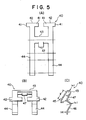
- the terminal spring 40 is made of an H-shaped thin spring sheet having two head portions 42 each having a lug 41 at each end, two parallel leg portions 44, and a connecting portion 43 to connect the two leg portions 44 together, and the sheet is bent at the connecting portion 43 in a hairpin-like shape.
- the bent leg portions 44 are respectively further bent twice so as to have two wavy steps.
- the overall cross sectional shape of the terminal spring 40 has a substantially inverted U-shaped form with one longer leg as shown in Fig. 5(C).
- the head portions 42 serve as engaging pieces 45 each with the hairpin-like portion forming a main curved portion a, the first and the second bent portions serving as subcurved portions b and c, respectively, and the adjacency of the third curved portion d serve as contacting pieces 46.
- a projecting piece 47 is formed at the connecting portion 43 centrally, acting as a stopper to temporarily hold the terminal spring 40 when it is mounted on the terminal portion 30 and 49 is a terminal piece (See Figs. 2 and 4).
- the reference numeral 5 indicates a detecting portion the frame of which is all molded plastic resin as in the base portion 2, and which comprises a head part, a printed circuit board, a dark box comprising an upper portion and a lower portion arranged one upon another, and a cover, etc. to be described later.
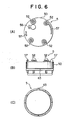
- the head part 50 constitutes one of the portions of the detecting portion 5 and has a hollow cylindrical form with its top end being closed by a wall (See also Fig. 6).
- Each setscrews 51 are formed at their upper ends with flanges 52, and through-holes 53 pass through the head part 50 vertically.
- the through-holes 53 are adapted to be passed through by the setscrews 51, respectively.
- An annular stepped portion 54 is formed around the inner periphery of a lower portion of the head part 50, a plurality of hooks 53 are formed at the lower end periphery of the head part 50, an elastic cap 56 for test terminals is fit in the top cover of the head part 50, and arcuate guide walls 57 project from the upper surface of the top cover of the head part 50.
- circuit elements 61 such as resistors, capacitors, etc. mounted on the upper surface of the printed circuit board 60, a conductor 62 having a threaded hole to screw on the lower part of setscrew 51, and a confirmation lamp 63.
- the conductor 62 is secured to the printed circuit board 60 to constitute a portion of a detecting circuit.
- the confirmation lamp 63 is suspended from the printed circuit board 60 so as to be visible from the outside, and is here an LED.
- the dark box 70 is made of a molded black plastic resin material which comprises a dark box body or upper portion 71 integral with the printed circuit board 60 and a cover body or lower portion 72 to be mounted on the dark box body 71 from below.
- a pushing portion 73 is formed on the upper surface of the dark box body 71 so as to slightly project upwards therefrom , and a projecting flange 74 is formed around the outer periphery of the dark box body 71 near its upper portion so as to engage with hooks 55 formed in the head part 50 around its lower end periphery.
- the reference numeral 75 is a labyrinth constituted by a plurality of light-shielding columns, formed at the periphery of the dark box body 71 at the under surface of its top cover.
- the labyrinth 75 is so constituted that although it allows the surrounding air or smoke to enter into the inside of the dark box 70, it prevents the light from entering thereinto from the outside.
- Key-like formed claws 76 are for the cover body 72 of the dark box 70, and 77 and 78 are a light projecting element and a light receiving elements, respectively, 79 is a test lamp using a light emitting diode (See also Fig. 10), 80 is a light-shielding column surrounding the test lamp 79, and 81 are positioning holes.
- the light-shielding column 80 comprises paired two light-shielding columns each having a J-shaped special configuration and constituting a part of the labyrinth 75, surrounding the test lamp 79.
- Protruded pieces 82 and 83 project from the inner surface of the cover body 72 (See also Fig. 8), with three locating pins 84 also projecting therefrom.
- the protruded pieces 82 and 83 face the light projecting elements 77 and the light receiving element 78, respectively, and the pins 84 correspond to the positioning holes 81, respectively.
- a screen 85 provided for preventing the entry of insects is made of a thin metal sheet, and a cover 86 for the detecting part 5 is provided around the screen 85.
- the screen 85 is made in a band-like configuration, and it is constituted so as to form a cylindrical shape with the projections formed at one of the ends being inserted into narrow insertion grooves formed at the other end correspondingly.
- Air flow passages formed 87 are in the cover 86 as are 88 hooks to engage the key-shaped claws 76, and 89 is an insertion hole to insert the confirmation lamp 83 ( See Fig. 9).
- the cover 86 covers the dark box 70 from below with the engaging hooks 88 engaging the engaging claws 76 and the screen 85 for preventing the entry of insects put therebetween.
- Fig. 11 is a block diagram showing the detecting circuit 90 of the detecting portion 5 where 91 is a pulse lamp circuit for the light projecting element 77, 92 an amplifying circuit to amplify the output of the light receiving element 78, and 93 is a switching circuit.
- the switching circuit 93 comprises a threshold circuit, an SCR, etc. and 94 is a test circuit to light the test lamp 79 which comprises e.g. a test switch 95 adapted to be controlled from the receiver side and an electrical source 96 for testing.
- the light-scattering-type smoke detector in accordance with the present invention having a constitution as described above is assembled in a manner as described below:
- One of the shaped terminal springs 40 is inserted into one of the rectilinear walls 33 of the terminal portions 30 in the base part 2 shown in Figs. 3 and 4 with the terminal spring 40 being laid on the terminal piece 49 previously laid on the terminal portion 30.
- the terminal spring 40 is temporarily held to the terminal portion 30 with the projecting piece 47 elastically abutting the receiving pedestal 34.
- On the terminal spring 40 thus held temporarily one of the terminal plates 37 is laid, and one of the fastening screws 39 is screwed into the threaded hole of one of the mounting seats 36 so that the terminal plate 37 is secured in a slant state along the sloped steps 32, thus mounting one of the terminal portions 30.
- the other three terminal portions have the terminal springs 40 and the terminal pieces 49, respectively, mounted therein.
- both head portions 42 come near the introduction grooves 31, respectively, and the vicinities of the end portions of the engaging pieces 45 confront the detecting hole 38 formed in the terminal plate 37.
- the base portion 2 in the terminal portions 30 of which the terminal plates 37, etc., have thus been assembled may be mounted on the ceiling 1 about a ceiling opening 11 by screwing fastening screws through two fastening holes 22 into the ceiling, respectively, with the base portion 2 being rotated in a clockwise direction as viewed in Fig. 2.
- the wiring 12 is let down through the ceiling opening 11 and drawn down through the opening 21 of the base portion 2.
- the core wires of the wiring 12 thus drawn down are inserted into the terminal portion 30 through the insertion grooves 31.
- the ends of the core wires travel further along the terminal plate 37 with the engaging pieces 45 of the terminal springs 40 being pressed down.
- the contacting pieces 46 of the terminal spring 40 are abutted so that the core wires are held between the terminal plate 37 and the contacting pieces 46 under the action of the terminal spring 40.
- the state of the wiring 12 is shown in Fig. 1.
- the wiring 12 is held by the ends of the engaging pieces 45 which theoretically generate a strong spring force owing to the shortness of the length 1 from the principal curved portion a, as seen in Fig. 5(c), but present a broad elastic displacement through the sub-curved portions b and c, whereby electrical conduction is attained by a relatively small spring pressure. Therefore, the spring pressure of the terminal spring 40 is effectively utilized.
- the wiring 12 drawn down is inserted obliquely upwards from below the slanted terminal plate 37 the wiring operation can be carried out quite easily without having to unduly crane one's neck during installation on the ceiling 1.
- the other wiring 12 may be inserted through the other insertion grooves 31.
- the connection of the wiring 12 to the terminal portions 30 for input to and output from them is completed.
- the terminal spring 40 deforms at many portions including the sub-curved portions b and c in addition to the principal curved portion a. As a result, the deformation is distributed so that the large deformation due to the external force can be achieved, substantially no plastic deformation of the engaging pieces 45 of the terminal spring 40 occurring.
- the assembly of the detecting portion 5 is carried out in the following manner:
- the body 71 of the dark box 70 is laid on the surface of the printed circuit board 60 under the upper surface on which the circuit elements such as chip members, etc., have previously been mounted, and the respective lead receiving element 78 and test lamp 79 all contained in the chamber of the dark box body 71 are drawn out therefrom, respectively, onto the upper surface of the printed circuit board 60.
- the lead wires thus drawn out are soldered on the upper surface of the printed circuit board 60, whereby the dark box body 71 and the printed circuit board 60 are integrated.
- the printed circuit board 60 integrated with the dark box body 71 is put into the head part 50 constituting one of the parts of the detecting portion 5 from below.
- the periphery of the printed circuit board 60 together with the dark box body 71 is forced into the stepped portion 54 of the head part 50 so that the projecting flange 74 of the printed circuit board 60 engages the hooks 55 formed on the head part 50.
- the dark box body 71 is secured to the underside of the head part 50 together with the printed circuit board 60 owing to the engagement of the projecting flange 74 and the hooks 55.
- the four setscrews 51 have been inserted through the through-holes 53 formed in the head part 50 they are screwed into the conductors 62 secured to the printed circuit board 60, respectively, to be secured thereto.
- the printed circuit board 60 is made to fit somewhat tightly into the head part 50 so that the pressing face 73 of the dark box body 71 pushes the under surface of the printed circuit board 60.
- the periphery of the elastic printed circuit board 60 tightly abuts the stepped portion 54, making it possible to hermetically seal the electrical circuit portion within the head part 50.
- the pins 84 are respectively inserted into the three positioning holes 31 at the side of the dark box body 71, respectively, and the cover body 72 of the dark box 70 is put on the dark box body 71.
- the detecting portion 5 thus assembled is mounted on the base portion 2 from below, the base portion 2 already having the connection to the wirings 12 completed. Similar to the previously described mounting of the printed circuit board 60 the mounting or dismounting of the detecting portion 5 to or from the base part 2 is also carried out by inserting it from below and rotating it relative to the base portion 2. However, when inserting the detecting portion 5 (or its head part 50) into the base part 2 the setscrews 51 fix them together and make the electrical connection between them.
- the setscrews 51 are positioned so as to be on the line X-X diametrically connecting the ends of the terminal pieces 49 as shown in Fig. 2 and the detecting portion 5 is pushed upwards.
- the detecting portion 5 is then rotated clockwise by an angle as viewed in Fig. 2 relative to the base portion 2 and in this state the flanges 52 of setscrews 51 go beyond the projections m of the arcuate engaging edges 35, the detecting portion 5 fitting between the engaging edges 35 and the terminal pieces 49 owing to their elasticity so that the detecting portion 5 is rigidly mounted on the engaging edges 35.
- the guide walls 57 on the upper surface of the head part 50 guide the detecting portion 5 with the mounting position thereof being determined by the guide walls 57 and the projections m act to prevent the flange 52 from falling out.
- the electrical circuit portion of the detecting portion 5 having been mounted to the base portion 2 electrically connected to the wiring 12 through the terminal springs 40, terminal pieces 48, setscrews 51, conductors 62 and the printed circuit board 60.
- groups of smoke detectors respectively mounted on ceilings of the respective stories are connected to a receiving station in parallel through the wiring 12.
- the smoke detector described above operates as follows:
- the combustion products rise upwards and enters the smoke detector mounted on the ceiling through the flow passages 87 in the detecting portion 5 to enter into the dark box 70 while the light projecting element 77 within the dark box 70 is periodically pulsated by the lamp circuit 91.
- the light projected from the light projecting element 77 is scattered by the smoke flowing into the dark box 70, and the light receiving element 78 receives the scattered light.
- the detected signal by the light receiving element 78 is amplified by the amplifying circuit 99, and when the density of the smoke exceeds a predetermined threshold the switching circuit 93 is operated.
- the output of the switching circuit 93 is fed to the receiving station through wiring 12, the zone of the fire being indicated, and the fire alarm is given by warning devices located at various portions in the building. Simultaneously the response lamp 63 is turned on, indicating which smoke detector is operating.
- a control signal is supplied to the smoke detectors from the receiving station through the wiring 12 or special wiring to turn on the test switch 95 of the test circuit 94, lighting the test lamp 79.
- the light quantity irradiated is previously selected to be equal to light scattered in the dark box 70.
- a fire signal is supplied to the receiving station from the switching circuit 73 through the amplifying circuit 92.
- the detecting portion 5 can be dismounted from the base portion 2, which is mounted on the ceiling 1, by rotating the detecting portion 5 counterclockwise relative to the base portion 2 for a definite angle.
- the electrically conductive side of the printed circuit board 60 is exposed to the outside so that a circuit test, etc., of the circuit elements can be carried out.
- the cover 86 of the detecting portion 5 is dismounted together with the screen 85 for keeping out insects and the cover body 72 of the dark box 70 is pulled out the inside of the dark box 70 is exposed to the outside. As a result, moisture on the labyrinth 75 and dust accumulated on the screen 85 for keeping out insects can be removed.
- the number may be increased or decreased as needed.
- the wiring 12 is connected to the terminal portions 30 of the base portion 2 after it has been mounted on the ceiling 1 it may also be possible to mount the base portion 2 on the ceiling 1 after the wiring 12 is connected to the terminal portions 30 thereof.
- the base portion 2 is described and shown to be an exposed type where it is externally mounted on the ceiling 1 the present invention also applies to a recessed type smoke detector in which the base portion 2 is embedded in the ceiling 1.
- terminal plates 37 are fixed to the terminal portions 30 of the base portion 2 by fastening screws 39
- the terminal plates 37 may also be fixed by suitable means such as a force fit, etc., in place of the fastening screws 39.
- the light-scattering-type smoke detector in accordance with the present invention is composed of a detecting portion which comprises a head part removably mounted to the base portion, adapted to be secured to a ceiling, by means of setscrews, a printed circuit board fit in to the head part secured thereto by the setscrews with the circuit elements arranged on the upper surface thereof being connected to the terminal portions.
- a dark box composed of upper and lower portions put one upon another and adapted to be removealy mounted on the head part with the light projecting element and the light receiving element provided within it, and a dark box cover removably surrounding the dark box.
- the base portion utilizes self-locking fixtures and the terminal plates are constituted so that the wiring can be inserted obliquely upwards the wiring and mounting operation is facilitated, and the constitution can be made more compact. Also, since the terminal plates are made to be fixed obliquely the radial distance of the base portion to be occupied by the terminal plates can be reduced, and the overall dimensions can be reduced more compact.
- the detecting part can be made compact, allowing also an easy operation for the operation test of the detecting part.
- the terminal portions of the base portion are provided with protruded arcuate edges around the inner surface thereof and the spring plates, and the detecting portion is provided with setscrews each having a flange which acts both as an input/output terminal and a mounting fixture, the wiring and mounting operation facilitated and the overall dimensions reduced because there is no need to use screw terminals, knife fixtures or the like as conventionally required.
- a light-scattering-type smoke detector can be provided which has such advantageous features as allowing easy maintenance and inspection, etc.
Landscapes
- Chemical & Material Sciences (AREA)
- Analytical Chemistry (AREA)
- Business, Economics & Management (AREA)
- Emergency Management (AREA)
- Physics & Mathematics (AREA)
- General Physics & Mathematics (AREA)
- Fire-Detection Mechanisms (AREA)
Applications Claiming Priority (6)
| Application Number | Priority Date | Filing Date | Title |
|---|---|---|---|
| JP1112034A JP2536783B2 (ja) | 1989-05-02 | 1989-05-02 | 光電式煙感知器 |
| JP51617/89U | 1989-05-02 | ||
| JP112034/89 | 1989-05-02 | ||
| JP5161789U JPH02145494U (fr) | 1989-05-02 | 1989-05-02 | |
| JP5391889 | 1989-05-12 | ||
| JP53918/89U | 1989-05-12 |
Publications (3)
| Publication Number | Publication Date |
|---|---|
| EP0399244A2 true EP0399244A2 (fr) | 1990-11-28 |
| EP0399244A3 EP0399244A3 (fr) | 1991-05-02 |
| EP0399244B1 EP0399244B1 (fr) | 1995-02-15 |
Family
ID=27294373
Family Applications (1)
| Application Number | Title | Priority Date | Filing Date |
|---|---|---|---|
| EP90108035A Expired - Lifetime EP0399244B1 (fr) | 1989-05-02 | 1990-04-27 | Détecteur de fumée du type à lumière dispersée |
Country Status (3)
| Country | Link |
|---|---|
| US (1) | US5021677A (fr) |
| EP (1) | EP0399244B1 (fr) |
| DE (1) | DE69016828T2 (fr) |
Cited By (6)
| Publication number | Priority date | Publication date | Assignee | Title |
|---|---|---|---|---|
| EP0707207A2 (fr) | 1994-10-10 | 1996-04-17 | Fritz Fuss GmbH & Co. | Détecteur de fumée |
| WO1996021208A1 (fr) * | 1995-01-04 | 1996-07-11 | Caradon Gent Limited | Perfectionnements apportes a des detecteurs de fumee ou s'y rapportant |
| GB2426323A (en) * | 2005-05-16 | 2006-11-22 | Fire Fighting Entpr Ltd | Infra-red beam smoke detection system |
| EP2233916A3 (fr) * | 2009-03-27 | 2013-08-28 | Nohmi Bosai Ltd. | Brandmelder |
| EP3270362A1 (fr) * | 2017-02-07 | 2018-01-17 | Siemens Schweiz AG | Détecteur d'incendie comprenant une chambre de mesure et un support de circuit destiné à disposer ensemble un détecteur d'incendie de la chambre de mesure et au moins un autre capteur destiné à détecter une grandeur de mesure dans l'environnement à l'extérieur du détecteur d'incendie |
| CN116380741A (zh) * | 2023-06-05 | 2023-07-04 | 湖北圣信特种设备检测有限公司 | 一种锅炉燃烧烟气成分检测装置和检测方法 |
Families Citing this family (28)
| Publication number | Priority date | Publication date | Assignee | Title |
|---|---|---|---|---|
| DE69317147T2 (de) * | 1992-04-25 | 1998-10-01 | Nohmi Bosai Ltd | Feuermelder |
| DE4328671B4 (de) * | 1992-08-28 | 2005-02-17 | Hochiki K.K. | Streulichtrauchmelder |
| JP2648560B2 (ja) * | 1993-04-09 | 1997-09-03 | ホーチキ株式会社 | 散乱光式煙感知器 |
| US5546074A (en) * | 1993-08-19 | 1996-08-13 | Sentrol, Inc. | Smoke detector system with self-diagnostic capabilities and replaceable smoke intake canopy |
| US6501810B1 (en) | 1998-10-13 | 2002-12-31 | Agere Systems Inc. | Fast frame synchronization |
| GB9417484D0 (en) * | 1993-09-07 | 1994-10-19 | Hochiki Co | Light scattering type smoke sensor |
| US5420440A (en) * | 1994-02-28 | 1995-05-30 | Rel-Tek Corporation | Optical obscruation smoke monitor having a shunt flow path located between two access ports |
| JP3331072B2 (ja) * | 1994-11-11 | 2002-10-07 | ホーチキ株式会社 | ベース組込型アドレスユニットのピン嵌合構造 |
| JP2787001B2 (ja) * | 1994-12-12 | 1998-08-13 | ホーチキ株式会社 | 光電式煙感知器 |
| US7015476B2 (en) * | 1999-04-14 | 2006-03-21 | Juni Jack E | Single photon emission computed tomography system |
| US7105825B2 (en) * | 1999-04-14 | 2006-09-12 | Juni Jack E | Single photon emission computed tomography system |
| JP3848488B2 (ja) * | 1999-04-30 | 2006-11-22 | ニッタン株式会社 | 火災感知器 |
| US6778091B2 (en) * | 2001-01-09 | 2004-08-17 | Qualey, Iii James R. | Smoke chamber |
| ATE297527T1 (de) * | 2001-03-14 | 2005-06-15 | Acbond Ltd | Verbesserungen mit bezug auf rauchmelder |
| US20030197618A1 (en) * | 2002-04-23 | 2003-10-23 | Alex Hsieh | Smoke collector case |
| PT1376504E (pt) * | 2002-06-20 | 2006-07-31 | Siemens Schweiz Ag | Detector de fumos por difusao de luz |
| EP2425410B1 (fr) * | 2009-05-01 | 2013-11-06 | Marshell Electrical Contractors Limited | Détecteurs |
| JP6145041B2 (ja) * | 2011-06-30 | 2017-06-07 | ホーチキ株式会社 | 散乱光式煙検出装置 |
| US9091388B2 (en) * | 2012-07-13 | 2015-07-28 | Walter Kidde Portable Equipment, Inc. | Mounting assembly with automatic activation for alarm units |
| US9459208B2 (en) * | 2013-10-04 | 2016-10-04 | Tyco Fire & Security Gmbh | Duct detector with remote airflow test capability |
| US9501925B2 (en) * | 2013-12-23 | 2016-11-22 | White Stagg, Llc | Modular alert system |
| DE102015004458B4 (de) | 2014-06-26 | 2016-05-12 | Elmos Semiconductor Aktiengesellschaft | Vorrichtung und Verfahren für einen klassifizierenden, rauchkammerlosen Luftzustandssensor zur Prognostizierung eines folgenden Betriebszustands |
| KR101874970B1 (ko) * | 2014-07-14 | 2018-07-05 | 펜월 컨트롤즈 오브 재팬, 리미티드 | 광전식 연기 감지기 |
| DE102014019773B4 (de) | 2014-12-17 | 2023-12-07 | Elmos Semiconductor Se | Vorrichtung und Verfahren zur Unterscheidung von festen Objekten, Kochdunst und Rauch mittels des Displays eines Mobiltelefons |
| DE102014019172B4 (de) | 2014-12-17 | 2023-12-07 | Elmos Semiconductor Se | Vorrichtung und Verfahren zur Unterscheidung von festen Objekten, Kochdunst und Rauch mit einem kompensierenden optischen Messsystem |
| JP6440848B2 (ja) | 2015-08-25 | 2018-12-19 | 日本フェンオール株式会社 | 光電式煙感知器 |
| EP4239612A1 (fr) * | 2022-03-04 | 2023-09-06 | Carrier Corporation | Détecteur de fumée avec chambre de détection de décalage et blindage |
| WO2023172947A1 (fr) * | 2022-03-09 | 2023-09-14 | Integrity Communications Solutions, Inc. | Capteur de gaz en ligne et procédés de détection |
Citations (4)
| Publication number | Priority date | Publication date | Assignee | Title |
|---|---|---|---|---|
| US3767917A (en) * | 1970-07-23 | 1973-10-23 | Cerberus Ag | Ionizing-type fire alarm sensor |
| US4168438A (en) * | 1977-04-05 | 1979-09-18 | Matsushita Electric Works, Ltd. | Light scattering type smoke detector |
| EP0014251A1 (fr) * | 1979-01-23 | 1980-08-20 | Cerberus Ag | Dispositif d'accouplement pour avertisseur d'incendie |
| GB2203238A (en) * | 1987-03-27 | 1988-10-12 | Hochiki Co | Photoelectric smoke detector |
Family Cites Families (2)
| Publication number | Priority date | Publication date | Assignee | Title |
|---|---|---|---|---|
| US4216377A (en) * | 1977-06-27 | 1980-08-05 | Nittan Company, Limited | Light scattering smoke detector |
| US4269510A (en) * | 1978-12-21 | 1981-05-26 | Cerberus Ag | Smoke detector |
-
1990
- 1990-04-26 US US07/515,181 patent/US5021677A/en not_active Expired - Fee Related
- 1990-04-27 DE DE69016828T patent/DE69016828T2/de not_active Expired - Fee Related
- 1990-04-27 EP EP90108035A patent/EP0399244B1/fr not_active Expired - Lifetime
Patent Citations (4)
| Publication number | Priority date | Publication date | Assignee | Title |
|---|---|---|---|---|
| US3767917A (en) * | 1970-07-23 | 1973-10-23 | Cerberus Ag | Ionizing-type fire alarm sensor |
| US4168438A (en) * | 1977-04-05 | 1979-09-18 | Matsushita Electric Works, Ltd. | Light scattering type smoke detector |
| EP0014251A1 (fr) * | 1979-01-23 | 1980-08-20 | Cerberus Ag | Dispositif d'accouplement pour avertisseur d'incendie |
| GB2203238A (en) * | 1987-03-27 | 1988-10-12 | Hochiki Co | Photoelectric smoke detector |
Cited By (12)
| Publication number | Priority date | Publication date | Assignee | Title |
|---|---|---|---|---|
| EP0707207A2 (fr) | 1994-10-10 | 1996-04-17 | Fritz Fuss GmbH & Co. | Détecteur de fumée |
| EP0707207A3 (fr) * | 1994-10-10 | 1998-05-13 | Fritz Fuss GmbH & Co. | Détecteur de fumée |
| WO1996021208A1 (fr) * | 1995-01-04 | 1996-07-11 | Caradon Gent Limited | Perfectionnements apportes a des detecteurs de fumee ou s'y rapportant |
| GB2426323A (en) * | 2005-05-16 | 2006-11-22 | Fire Fighting Entpr Ltd | Infra-red beam smoke detection system |
| EP2233916A3 (fr) * | 2009-03-27 | 2013-08-28 | Nohmi Bosai Ltd. | Brandmelder |
| CN103514705A (zh) * | 2009-03-27 | 2014-01-15 | 能美防灾株式会社 | 火灾探测器 |
| AU2010201098B2 (en) * | 2009-03-27 | 2015-06-04 | Nohmi Bosai Ltd. | Fire detector |
| CN103514705B (zh) * | 2009-03-27 | 2016-08-10 | 能美防灾株式会社 | 火灾探测器 |
| EP3270362A1 (fr) * | 2017-02-07 | 2018-01-17 | Siemens Schweiz AG | Détecteur d'incendie comprenant une chambre de mesure et un support de circuit destiné à disposer ensemble un détecteur d'incendie de la chambre de mesure et au moins un autre capteur destiné à détecter une grandeur de mesure dans l'environnement à l'extérieur du détecteur d'incendie |
| EP3270362B1 (fr) | 2017-02-07 | 2019-01-02 | Siemens Schweiz AG | Détecteur d'incendie comprenant une chambre de mesure et un support de circuit destiné à disposer ensemble un détecteur d'incendie de la chambre de mesure et au moins un autre capteur destiné à détecter une grandeur de mesure dans l'environnement à l'extérieur du détecteur d'incendie |
| CN116380741A (zh) * | 2023-06-05 | 2023-07-04 | 湖北圣信特种设备检测有限公司 | 一种锅炉燃烧烟气成分检测装置和检测方法 |
| CN116380741B (zh) * | 2023-06-05 | 2023-08-25 | 湖北圣信特种设备检测有限公司 | 一种锅炉燃烧烟气成分检测装置和检测方法 |
Also Published As
| Publication number | Publication date |
|---|---|
| DE69016828T2 (de) | 1995-08-24 |
| US5021677A (en) | 1991-06-04 |
| DE69016828D1 (de) | 1995-03-23 |
| EP0399244A3 (fr) | 1991-05-02 |
| EP0399244B1 (fr) | 1995-02-15 |
Similar Documents
| Publication | Publication Date | Title |
|---|---|---|
| US5021677A (en) | Light-scattering-type smoke detector | |
| KR101019839B1 (ko) | 화재 탐지기 | |
| US4238679A (en) | Dual-chamber ionization smoke detector assembly | |
| US5461550A (en) | Canopy mounting device for exit signs and the like | |
| KR100998373B1 (ko) | 산란된 광 스모크 탐지기 | |
| US4139770A (en) | Smoke alarm | |
| US7969321B2 (en) | Smoke detector | |
| US6411201B1 (en) | Strobe alarm with strobe intensity selector switch | |
| US4510488A (en) | Passive infrared intrusion detector | |
| US4584485A (en) | Optical block in smoke detectors | |
| US7375617B2 (en) | Evacuation appliance | |
| KR101475086B1 (ko) | 광전식 연기 감지기 | |
| US3985453A (en) | Light scattering type smoke detector | |
| JP3404801B2 (ja) | 感知器の感知ヘッド | |
| JP3766912B2 (ja) | 火災感知器 | |
| JP2536783B2 (ja) | 光電式煙感知器 | |
| RU2285297C1 (ru) | Датчик пожарный | |
| GB2396752A (en) | Connector base for detector | |
| JP2526375Y2 (ja) | 火災感知器 | |
| JP2506481Y2 (ja) | 光電式煙感知器 | |
| JP3716351B2 (ja) | 火災感知器の取外し装置 | |
| JP2540599Y2 (ja) | 火災感知器 | |
| JP2565208Y2 (ja) | 輻射式火災感知器 | |
| JP2528862Y2 (ja) | 光電式煙感知器 | |
| KR20220108941A (ko) | 미세먼지 측정장치 |
Legal Events
| Date | Code | Title | Description |
|---|---|---|---|
| PUAI | Public reference made under article 153(3) epc to a published international application that has entered the european phase |
Free format text: ORIGINAL CODE: 0009012 |
|
| AK | Designated contracting states |
Kind code of ref document: A2 Designated state(s): CH DE FR GB LI |
|
| PUAL | Search report despatched |
Free format text: ORIGINAL CODE: 0009013 |
|
| AK | Designated contracting states |
Kind code of ref document: A3 Designated state(s): CH DE FR GB LI |
|
| 17P | Request for examination filed |
Effective date: 19910518 |
|
| 17Q | First examination report despatched |
Effective date: 19931210 |
|
| GRAA | (expected) grant |
Free format text: ORIGINAL CODE: 0009210 |
|
| AK | Designated contracting states |
Kind code of ref document: B1 Designated state(s): CH DE FR GB LI |
|
| REF | Corresponds to: |
Ref document number: 69016828 Country of ref document: DE Date of ref document: 19950323 |
|
| ET | Fr: translation filed | ||
| REG | Reference to a national code |
Ref country code: CH Ref legal event code: PL |
|
| REG | Reference to a national code |
Ref country code: CH Ref legal event code: AEN |
|
| PLBE | No opposition filed within time limit |
Free format text: ORIGINAL CODE: 0009261 |
|
| STAA | Information on the status of an ep patent application or granted ep patent |
Free format text: STATUS: NO OPPOSITION FILED WITHIN TIME LIMIT |
|
| 26N | No opposition filed | ||
| PGFP | Annual fee paid to national office [announced via postgrant information from national office to epo] |
Ref country code: FR Payment date: 19990325 Year of fee payment: 10 |
|
| PGFP | Annual fee paid to national office [announced via postgrant information from national office to epo] |
Ref country code: CH Payment date: 19990330 Year of fee payment: 10 |
|
| PGFP | Annual fee paid to national office [announced via postgrant information from national office to epo] |
Ref country code: GB Payment date: 20000426 Year of fee payment: 11 |
|
| PG25 | Lapsed in a contracting state [announced via postgrant information from national office to epo] |
Ref country code: LI Free format text: LAPSE BECAUSE OF NON-PAYMENT OF DUE FEES Effective date: 20000430 Ref country code: CH Free format text: LAPSE BECAUSE OF NON-PAYMENT OF DUE FEES Effective date: 20000430 |
|
| PGFP | Annual fee paid to national office [announced via postgrant information from national office to epo] |
Ref country code: DE Payment date: 20000624 Year of fee payment: 11 |
|
| REG | Reference to a national code |
Ref country code: CH Ref legal event code: PL |
|
| PG25 | Lapsed in a contracting state [announced via postgrant information from national office to epo] |
Ref country code: FR Free format text: LAPSE BECAUSE OF NON-PAYMENT OF DUE FEES Effective date: 20001229 |
|
| REG | Reference to a national code |
Ref country code: FR Ref legal event code: ST |
|
| PG25 | Lapsed in a contracting state [announced via postgrant information from national office to epo] |
Ref country code: GB Free format text: LAPSE BECAUSE OF NON-PAYMENT OF DUE FEES Effective date: 20010427 |
|
| GBPC | Gb: european patent ceased through non-payment of renewal fee |
Effective date: 20010427 |
|
| PG25 | Lapsed in a contracting state [announced via postgrant information from national office to epo] |
Ref country code: DE Free format text: LAPSE BECAUSE OF NON-PAYMENT OF DUE FEES Effective date: 20020201 |