EP0396946B1 - Lupenanordnung - Google Patents
Lupenanordnung Download PDFInfo
- Publication number
- EP0396946B1 EP0396946B1 EP90107499A EP90107499A EP0396946B1 EP 0396946 B1 EP0396946 B1 EP 0396946B1 EP 90107499 A EP90107499 A EP 90107499A EP 90107499 A EP90107499 A EP 90107499A EP 0396946 B1 EP0396946 B1 EP 0396946B1
- Authority
- EP
- European Patent Office
- Prior art keywords
- magnifying glass
- section
- air gap
- cylindrical section
- glass arrangement
- Prior art date
- Legal status (The legal status is an assumption and is not a legal conclusion. Google has not performed a legal analysis and makes no representation as to the accuracy of the status listed.)
- Expired - Lifetime
Links
- 239000011521 glass Substances 0.000 claims description 25
- 230000003287 optical effect Effects 0.000 description 6
- 230000002093 peripheral effect Effects 0.000 description 4
- 239000000463 material Substances 0.000 description 3
- 238000011156 evaluation Methods 0.000 description 2
- 229920003229 poly(methyl methacrylate) Polymers 0.000 description 2
- 239000004926 polymethyl methacrylate Substances 0.000 description 2
- 239000000853 adhesive Substances 0.000 description 1
- 230000001070 adhesive effect Effects 0.000 description 1
- 239000003570 air Substances 0.000 description 1
- POIUWJQBRNEFGX-XAMSXPGMSA-N cathelicidin Chemical compound C([C@@H](C(=O)N[C@@H](CCCNC(N)=N)C(=O)N[C@@H](CCCCN)C(=O)N[C@@H](CO)C(=O)N[C@@H](CCCCN)C(=O)N[C@@H](CCC(O)=O)C(=O)N[C@@H](CCCCN)C(=O)N[C@@H]([C@@H](C)CC)C(=O)NCC(=O)N[C@@H](CCCCN)C(=O)N[C@@H](CCC(O)=O)C(=O)N[C@@H](CC=1C=CC=CC=1)C(=O)N[C@@H](CCCCN)C(=O)N[C@@H](CCCNC(N)=N)C(=O)N[C@@H]([C@@H](C)CC)C(=O)N[C@@H](C(C)C)C(=O)N[C@@H](CCC(N)=O)C(=O)N[C@@H](CCCNC(N)=N)C(=O)N[C@@H]([C@@H](C)CC)C(=O)N[C@@H](CCCCN)C(=O)N[C@@H](CC(O)=O)C(=O)N[C@@H](CC=1C=CC=CC=1)C(=O)N[C@@H](CC(C)C)C(=O)N[C@@H](CCCNC(N)=N)C(=O)N[C@@H](CC(N)=O)C(=O)N[C@@H](CC(C)C)C(=O)N[C@@H](C(C)C)C(=O)N1[C@@H](CCC1)C(=O)N[C@@H](CCCNC(N)=N)C(=O)N[C@@H]([C@@H](C)O)C(=O)N[C@@H](CCC(O)=O)C(=O)N[C@@H](CO)C(O)=O)NC(=O)[C@H](CC=1C=CC=CC=1)NC(=O)[C@H](CC(O)=O)NC(=O)CNC(=O)[C@H](CC(C)C)NC(=O)[C@@H](N)CC(C)C)C1=CC=CC=C1 POIUWJQBRNEFGX-XAMSXPGMSA-N 0.000 description 1
- 230000004313 glare Effects 0.000 description 1
Images
Classifications
-
- G—PHYSICS
- G02—OPTICS
- G02B—OPTICAL ELEMENTS, SYSTEMS OR APPARATUS
- G02B25/00—Eyepieces; Magnifying glasses
- G02B25/02—Eyepieces; Magnifying glasses with means for illuminating object viewed
Definitions
- the invention relates to a magnifying glass arrangement with a magnifying glass body, which has a cylinder section and a convexly curved lens section provided thereon, which is rotationally symmetrical with respect to the cylinder axis.
- an evaluation coil for generating or evaluating a magnetic field is arranged in the outer peripheral region of the cylinder section, which lies in such a way that it is located in the area between the peripheral surface of the cylinder section and the course of the edge beam of the lens section through the cylinder section.
- the base when the base is viewed through the magnifying glass body, it is not visible to the user, because the light beam falling perpendicularly with respect to the base on the outer edge of the lens section is refracted inward towards the cylinder axis by the lens body in such a way that between it and the outer one Circumferential surface of the cylinder section Area remains that is not recognizable to the viewer due to the optical course of the edge beam.
- the evaluation coil located in this area is also not visible without the viewer having the impression that part of the lens body would be "opaque".
- a light source is normally provided above the magnifying glass body, the light of which falls through the magnifying glass body onto the surface to be viewed, or the surface to be viewed is illuminated from below.
- the first case it is difficult to avoid reflections and glare, and often the light from the light source reaching the magnifying glass body is partially shielded by the user.
- the lighting from below is usually structurally complex and can of course only be provided if the surface to be viewed is translucent.
- a magnifying glass body of the type mentioned at the outset is designed according to the invention in such a way that at least one lamp is provided in the cylinder section in the region between its peripheral surface and the course of the marginal ray of the lens section through the cylinder section and that at least the central region between the cylinder section and the lens section has an air gap and is designed such that the light emitted by the lamp is totally reflected on the surface of the cylinder section delimiting the air gap.
- a lamp is thus arranged in the region of the cylinder section which is not visible to the viewer due to the optical properties of the lens section.
- the light of this lamp falls in the cylinder section on a surface of the cylinder section delimiting the air gap between the cylinder section and the lens section and is totally reflected by this surface, i.e. the light emitted by the lamp in the direction of the lens section is reflected away from the lens section and falls on that by means of the magnifying glass arrangement surface to be viewed in order to illuminate it.
- the actual light source is not visible to the user, so that it does not impair the use of the magnifying glass arrangement.
- the light of the lamp falling on the surface to be viewed is accordingly reflected by the cylinder section and from there through the lens section into the eye of the beholder. Only a very small part of this light falls on the surface of the cylinder section delimiting the air gap at such an angle that total reflection occurs again.
- the thickness of the air gap should be as small as possible in order to avoid optical distortions.
- the surface of the cylinder section delimiting the air gap is generally concavely curved for this purpose.
- the air gap is preferably rotationally symmetrical to the cylinder axis. It can extend into the region of the edge beam of the lens section in order in this way to bring about a total reflection of the entire light emitted by the lamp upwards and obliquely upwards.
- lamps diametrically opposite one another in pairs. They can be arranged in an annular groove formed in the cylinder section and open radially outwards, so that they can be easily inserted and removed.
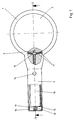
- Figure 1 shows partly as a view and partly in section of a magnifying glass arrangement in the form of a hand-held magnifier.
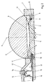
- Figure 2 shows a section along the line II-II.
- the magnifying glass arrangement shown has a carrier body 1, in which there is a through hole into which the lens body is inserted, which can be made of acrylic glass, for example.
- a handle 1 ' connects, in the interior 12 of which a battery 16 is accommodated, which is pressed by a spring 19 supported on a closure cap 18 against a contact held in the handle 1'.
- the lens body has a cylinder section 2 and a lens section 3, which is rotationally symmetrical with respect to the cylinder axis 4 and has a convex curvature.
- the cylinder section 2 and the lens section 3 lie flat on one another in their outer peripheral region and can for example by means of an adhesive of the same optical density as the material of the cylinder section 2 and the lens section 3.
- a narrow air gap 7 is formed between them, which is rotationally symmetrical to the cylinder axis 4 and which extends to the region of the edge beam 11. It is delimited by a flat surface 6 of the lens section 3 and a concave surface 5 of the cylinder section 2.
- annular groove 8 which is open radially outward and into which a plurality of lamps 9 are inserted diametrically opposite one another and are held in their position in a manner not shown.
- the lamps 9 are connected via lines 17 in the area of a support block 10 on the one hand with a through the handle 1 ', with a pole of the battery 16 connected line 13 and on the other hand with a contact 13'. If the provided in the handle 1 ', accessible from the outside button 14, the contact with the other pole of the battery 16 contact 15 is brought into contact with the contact 13' and the circuit for the lamps 9 is closed.
- the position of the lamps 9 is chosen so that they are outside the area delimited by the indicated edge beam 11 of the lens section 3, so that the lamp 9, as explained in the aforementioned DE-PS 35 20 293, in one for the User is not visible area.
- the light emitted by the lamps 9 upwards and diagonally upwards falls, as indicated by the arrows, onto the concave surface 5 of the cylinder section 2 adjoining the air gap 7 and is there on because of the selected shape of the surface 5 and because of the optical density difference between the material of the cylinder section 2 and the air in the air gap 7 totally reflected, ie the light reaches the surface to be viewed by means of the magnifying glass arrangement in the manner indicated by the arrows.
- the area to be viewed is thus well illuminated without the presence of the light source impairing the use of the magnifying glass arrangement.
Landscapes
- Physics & Mathematics (AREA)
- General Physics & Mathematics (AREA)
- Optics & Photonics (AREA)
- Lenses (AREA)
- Non-Portable Lighting Devices Or Systems Thereof (AREA)
- Length Measuring Devices By Optical Means (AREA)
Applications Claiming Priority (2)
| Application Number | Priority Date | Filing Date | Title |
|---|---|---|---|
| DE3915119A DE3915119C1 (OSRAM) | 1989-05-09 | 1989-05-09 | |
| DE3915119 | 1989-05-09 |
Publications (3)
| Publication Number | Publication Date |
|---|---|
| EP0396946A2 EP0396946A2 (de) | 1990-11-14 |
| EP0396946A3 EP0396946A3 (de) | 1991-03-27 |
| EP0396946B1 true EP0396946B1 (de) | 1992-07-22 |
Family
ID=6380314
Family Applications (1)
| Application Number | Title | Priority Date | Filing Date |
|---|---|---|---|
| EP90107499A Expired - Lifetime EP0396946B1 (de) | 1989-05-09 | 1990-04-20 | Lupenanordnung |
Country Status (4)
| Country | Link |
|---|---|
| US (1) | US5021933A (OSRAM) |
| EP (1) | EP0396946B1 (OSRAM) |
| DE (2) | DE3915119C1 (OSRAM) |
| ES (1) | ES2034795T3 (OSRAM) |
Families Citing this family (18)
| Publication number | Priority date | Publication date | Assignee | Title |
|---|---|---|---|---|
| EP0398062B1 (de) * | 1989-05-09 | 1994-08-31 | Aristo Graphic Systeme GmbH & Co. KG | Messlupenanordnung |
| WO1992001193A1 (en) * | 1990-07-11 | 1992-01-23 | Curtis Manufacturing Company, Inc. | Light apparatus for use with a compact computer video screen |
| US5165779A (en) * | 1991-04-19 | 1992-11-24 | Curtic Manufacturing Company Inc. | Compact combined light and magnifier apparatus for a hand-held computer with video screen and method |
| USD336655S (en) | 1991-07-01 | 1993-06-22 | Ming-Jin Lee | Magnifier with lamp |
| US5351424A (en) * | 1993-06-18 | 1994-10-04 | Schulle Gaylon E | Magnifier with light therethrough for needlework frame |
| EP0712502B1 (de) * | 1993-08-05 | 1997-03-26 | ESCHENBACH OPTIK GmbH + Co. | Optische lesevorrichtung |
| US5777805A (en) * | 1997-02-19 | 1998-07-07 | Gilman; Gary Duane | Magnifying device |
| DE19950899A1 (de) | 1999-10-22 | 2001-06-07 | Lifatec Gmbh Faseroptik Und Op | Beleuchtbare optische Vergrösserungsvorrichtung |
| US6322226B1 (en) | 2000-01-24 | 2001-11-27 | Daniel Dickson | Adjustable illumination apparatus having pre-focused led and magnification lens |
| US6373464B1 (en) * | 2000-02-04 | 2002-04-16 | R&R Design And Development Ltd. | Magnifying glass computer input device |
| US6502976B1 (en) | 2000-05-22 | 2003-01-07 | Jordan S. Bernhard | Illumination apparatus |
| US6538828B1 (en) * | 2001-10-24 | 2003-03-25 | Seamus Redmond | Magnifying page illuminator |
| US6903882B1 (en) * | 2004-01-08 | 2005-06-07 | Carson Optical | Magnifier with personalizable multipart handle |
| US7139136B2 (en) | 2004-03-29 | 2006-11-21 | Menu Mate, Llc | Handheld illuminating magnifier |
| US20080174987A1 (en) * | 2007-01-18 | 2008-07-24 | Siya, Inc. | Illuminated eye loupe |
| TWI383174B (zh) * | 2007-07-04 | 2013-01-21 | Univ Far East | Separable magnifying glass lamp |
| CN104345442B (zh) * | 2013-08-09 | 2016-08-31 | 振宇光学有限公司 | 可变换使用型态的放大镜装置 |
| US9904059B2 (en) * | 2016-07-08 | 2018-02-27 | Shirley Vetrone | Reading aid |
Family Cites Families (11)
| Publication number | Priority date | Publication date | Assignee | Title |
|---|---|---|---|---|
| DE469848C (de) * | 1928-12-29 | Merano G M B H Optik Feinmecha | Zweilinsige Handlupe mit elektrischer Beleuchtungseinrichtung | |
| DE481399C (de) * | 1925-06-28 | 1929-08-20 | Ernest Schaaff Dr | Lupe mit Beleuchtungsvorrichtung |
| DE498848C (de) * | 1929-03-02 | 1930-05-28 | Bamag Meguin Akt Ges | Fliehkraftkupplung |
| US1909662A (en) * | 1931-03-18 | 1933-05-16 | Swift & Anderson Inc | Magnifying and illuminating device |
| US2316301A (en) * | 1940-10-05 | 1943-04-13 | Ullman Paul | Illuminated magnifying lens and reading glass |
| US2586723A (en) * | 1948-09-25 | 1952-02-19 | Sakols Sidney | Illuminated magnifying lens |
| US3945717A (en) * | 1974-10-10 | 1976-03-23 | Ryder International Corporation | Illuminating magnifying lens structure |
| DE3520293C1 (de) * | 1985-06-07 | 1986-04-03 | Aristo Graphic Systeme Gmbh & Co Kg, 2000 Hamburg | Messlupenanordnung |
| US4751615A (en) * | 1986-08-07 | 1988-06-14 | International Marketing Concepts, Inc. | Page light |
| DE8816611U1 (de) * | 1987-03-31 | 1990-08-09 | Dr.-Ing. Willing GmbH, 8604 Scheßlitz | Inspektionsleuchte zur Ausleuchtung von Hohlräumen |
| US4859032A (en) * | 1988-04-15 | 1989-08-22 | Designs For Vision, Inc. | Hand-held magnifier apparatus |
-
1989
- 1989-05-09 DE DE3915119A patent/DE3915119C1/de not_active Expired - Fee Related
-
1990
- 1990-04-20 DE DE9090107499T patent/DE59000212D1/de not_active Expired - Fee Related
- 1990-04-20 ES ES199090107499T patent/ES2034795T3/es not_active Expired - Lifetime
- 1990-04-20 EP EP90107499A patent/EP0396946B1/de not_active Expired - Lifetime
- 1990-05-09 US US07/520,751 patent/US5021933A/en not_active Expired - Fee Related
Also Published As
| Publication number | Publication date |
|---|---|
| ES2034795T3 (es) | 1993-04-01 |
| US5021933A (en) | 1991-06-04 |
| DE3915119C1 (OSRAM) | 1990-06-13 |
| EP0396946A3 (de) | 1991-03-27 |
| DE59000212D1 (de) | 1992-08-27 |
| EP0396946A2 (de) | 1990-11-14 |
Similar Documents
| Publication | Publication Date | Title |
|---|---|---|
| EP0396946B1 (de) | Lupenanordnung | |
| DE19834374B4 (de) | Drehknopf eines Steuergerätes | |
| WO1996030972A1 (de) | Elektrisches verbindungsteil mit kontaktstiften oder -buchsen, wie stecker oder kupplung | |
| DE2817525A1 (de) | Optisches system mit variabler brennweite | |
| DE3515809A1 (de) | Optisches beleuchtungssystem fuer ein endoskop | |
| EP0157355A2 (de) | Taschenleuchte | |
| EP0398062B1 (de) | Messlupenanordnung | |
| DE3511350C2 (OSRAM) | ||
| DE2405386A1 (de) | Flutlichtbeleuchtung fuer skalen | |
| DE2632462A1 (de) | Leuchtdiode | |
| DE8119559U1 (de) | Einrichtung zur kontrolle der lichtquellenjustierung in auflichtmikroskopen | |
| EP0114030B1 (de) | Transmissionsdensitometer | |
| DE7627604U1 (de) | Kondensorlinsensystem | |
| DE467797C (de) | Lichtsignal fuer Eisenbahnen u. dgl. | |
| DE639969C (de) | Lichttonwiedergabeoptik | |
| DE928536C (de) | Einrichtung zur Markierung eines Leuchtsignals | |
| DE8803984U1 (de) | Uhr mit Zifferblattbeleuchtung | |
| DE641158C (de) | Vorrichtung zur Aufnahme diffus reflektierten Lichtes mit Hilfe von lichtelektrischen Zellen | |
| DE675909C (de) | Mikroskop-Objektiv mit Ringkondensor und einer Abschlussplatte | |
| DE202025105841U1 (de) | Lichtemittierender Knopf | |
| DE8210030U1 (de) | Vorrichtung fuer die untersuchung von objekten unter beleuchtung mit dunklem hintergrund | |
| DE925095C (de) | Signalleuchte, insbesondere fuer Eisenbahnzwecke | |
| DE3519190C2 (de) | Meßlichtprojektor für ein Spektralmeßgerät | |
| DE622601C (de) | Vergroesserungsglas | |
| AT223029B (de) | Mit Spiegeln versehener prismatischer Beleuchtungskörper |
Legal Events
| Date | Code | Title | Description |
|---|---|---|---|
| PUAI | Public reference made under article 153(3) epc to a published international application that has entered the european phase |
Free format text: ORIGINAL CODE: 0009012 |
|
| AK | Designated contracting states |
Kind code of ref document: A2 Designated state(s): BE CH DE ES FR GB IT LI NL SE |
|
| PUAL | Search report despatched |
Free format text: ORIGINAL CODE: 0009013 |
|
| RHK1 | Main classification (correction) |
Ipc: G01B 9/00 |
|
| 17P | Request for examination filed |
Effective date: 19901231 |
|
| AK | Designated contracting states |
Kind code of ref document: A3 Designated state(s): BE CH DE ES FR GB IT LI NL SE |
|
| 17Q | First examination report despatched |
Effective date: 19911223 |
|
| GRAA | (expected) grant |
Free format text: ORIGINAL CODE: 0009210 |
|
| AK | Designated contracting states |
Kind code of ref document: B1 Designated state(s): BE CH DE ES FR GB IT LI NL SE |
|
| REF | Corresponds to: |
Ref document number: 59000212 Country of ref document: DE Date of ref document: 19920827 |
|
| ET | Fr: translation filed | ||
| ITF | It: translation for a ep patent filed | ||
| GBT | Gb: translation of ep patent filed (gb section 77(6)(a)/1977) | ||
| PGFP | Annual fee paid to national office [announced via postgrant information from national office to epo] |
Ref country code: SE Payment date: 19930317 Year of fee payment: 4 |
|
| REG | Reference to a national code |
Ref country code: ES Ref legal event code: FG2A Ref document number: 2034795 Country of ref document: ES Kind code of ref document: T3 |
|
| PGFP | Annual fee paid to national office [announced via postgrant information from national office to epo] |
Ref country code: ES Payment date: 19930406 Year of fee payment: 4 |
|
| PGFP | Annual fee paid to national office [announced via postgrant information from national office to epo] |
Ref country code: BE Payment date: 19930421 Year of fee payment: 4 |
|
| PGFP | Annual fee paid to national office [announced via postgrant information from national office to epo] |
Ref country code: CH Payment date: 19930422 Year of fee payment: 4 |
|
| PGFP | Annual fee paid to national office [announced via postgrant information from national office to epo] |
Ref country code: NL Payment date: 19930430 Year of fee payment: 4 |
|
| PLBE | No opposition filed within time limit |
Free format text: ORIGINAL CODE: 0009261 |
|
| STAA | Information on the status of an ep patent application or granted ep patent |
Free format text: STATUS: NO OPPOSITION FILED WITHIN TIME LIMIT |
|
| 26N | No opposition filed | ||
| PG25 | Lapsed in a contracting state [announced via postgrant information from national office to epo] |
Ref country code: SE Effective date: 19940421 Ref country code: ES Free format text: LAPSE BECAUSE OF NON-PAYMENT OF DUE FEES Effective date: 19940421 |
|
| PG25 | Lapsed in a contracting state [announced via postgrant information from national office to epo] |
Ref country code: LI Effective date: 19940430 Ref country code: CH Effective date: 19940430 Ref country code: BE Effective date: 19940430 |
|
| BERE | Be: lapsed |
Owner name: ARISTO GRAPHIC SYSTEME G.M.B.H. & CO. K.G. Effective date: 19940430 |
|
| PG25 | Lapsed in a contracting state [announced via postgrant information from national office to epo] |
Ref country code: NL Effective date: 19941101 |
|
| NLV4 | Nl: lapsed or anulled due to non-payment of the annual fee | ||
| REG | Reference to a national code |
Ref country code: CH Ref legal event code: PL |
|
| EUG | Se: european patent has lapsed |
Ref document number: 90107499.7 Effective date: 19941110 |
|
| PGFP | Annual fee paid to national office [announced via postgrant information from national office to epo] |
Ref country code: GB Payment date: 19950410 Year of fee payment: 6 |
|
| PGFP | Annual fee paid to national office [announced via postgrant information from national office to epo] |
Ref country code: FR Payment date: 19950428 Year of fee payment: 6 |
|
| PG25 | Lapsed in a contracting state [announced via postgrant information from national office to epo] |
Ref country code: GB Effective date: 19960420 |
|
| GBPC | Gb: european patent ceased through non-payment of renewal fee |
Effective date: 19960420 |
|
| PG25 | Lapsed in a contracting state [announced via postgrant information from national office to epo] |
Ref country code: FR Effective date: 19961227 |
|
| REG | Reference to a national code |
Ref country code: FR Ref legal event code: ST |
|
| REG | Reference to a national code |
Ref country code: ES Ref legal event code: FD2A Effective date: 19990503 |
|
| PGFP | Annual fee paid to national office [announced via postgrant information from national office to epo] |
Ref country code: DE Payment date: 19991007 Year of fee payment: 10 |
|
| PG25 | Lapsed in a contracting state [announced via postgrant information from national office to epo] |
Ref country code: DE Free format text: LAPSE BECAUSE OF NON-PAYMENT OF DUE FEES Effective date: 20010201 |
|
| PG25 | Lapsed in a contracting state [announced via postgrant information from national office to epo] |
Ref country code: IT Free format text: LAPSE BECAUSE OF NON-PAYMENT OF DUE FEES;WARNING: LAPSES OF ITALIAN PATENTS WITH EFFECTIVE DATE BEFORE 2007 MAY HAVE OCCURRED AT ANY TIME BEFORE 2007. THE CORRECT EFFECTIVE DATE MAY BE DIFFERENT FROM THE ONE RECORDED. Effective date: 20050420 |