EP0395996A2 - Profiliervorrichtung für Ecken an plattenförmigen Werkstücken - Google Patents
Profiliervorrichtung für Ecken an plattenförmigen Werkstücken Download PDFInfo
- Publication number
- EP0395996A2 EP0395996A2 EP90107743A EP90107743A EP0395996A2 EP 0395996 A2 EP0395996 A2 EP 0395996A2 EP 90107743 A EP90107743 A EP 90107743A EP 90107743 A EP90107743 A EP 90107743A EP 0395996 A2 EP0395996 A2 EP 0395996A2
- Authority
- EP
- European Patent Office
- Prior art keywords
- workpiece
- profiling device
- milling
- motor
- housing
- Prior art date
- Legal status (The legal status is an assumption and is not a legal conclusion. Google has not performed a legal analysis and makes no representation as to the accuracy of the status listed.)
- Granted
Links
Images


Classifications
-
- B—PERFORMING OPERATIONS; TRANSPORTING
- B27—WORKING OR PRESERVING WOOD OR SIMILAR MATERIAL; NAILING OR STAPLING MACHINES IN GENERAL
- B27D—WORKING VENEER OR PLYWOOD
- B27D5/00—Other working of veneer or plywood specially adapted to veneer or plywood
- B27D5/006—Trimming, chamfering or bevelling edgings, e.g. lists
-
- B—PERFORMING OPERATIONS; TRANSPORTING
- B23—MACHINE TOOLS; METAL-WORKING NOT OTHERWISE PROVIDED FOR
- B23C—MILLING
- B23C3/00—Milling particular work; Special milling operations; Machines therefor
- B23C3/12—Trimming or finishing edges, e.g. deburring welded corners
Definitions
- the invention relates to a profiling device for corners according to the preamble of claim 1.
- the object of the present invention is therefore to provide a profiling device of the type mentioned, with which the corners of plate-shaped workpieces can be machined perfectly even with an irregular and asymmetrical cross section of the side surfaces, the device being able to be set quickly and safely to any desired cross section.
- the object is achieved by the feature specified in the characterizing part of claim 1.
- the milling tool Due to the pivotable mounting of the milling motor on the housing, the milling tool is swiveled from the top of the plate over the side surface to the underside, the milling motor being pressed radially against the workpiece in all angular positions. This results in an even contact pressure for the milling tool and a perfect milling pattern for any contours of the side surfaces.
- the milling motor can be easily and securely displaceably mounted on guide rods within the ring.
- a counterweight movable counter to the milling motor counteracts the weight of the milling motor, so that the same contact pressure is ensured in all angular positions.
- the housing to which the swivel member is attached can be moved against a base frame with support surfaces for the workpiece in the vertical direction. This makes it possible to adjust the center point of the swivel member so that it lies in the middle of the workpiece and by half the workpiece thickness from its front side surface. This ensures an optimal attack of the milling tool on the workpiece.
- a control unit which controls the displacement of the milling motor against the workpiece and its lifting and ensures a quick and safe milling process.
- the corner of a plate-shaped workpiece with an asymmetrical side surface is to be machined, then the workpiece must be turned over after machining the first corner, ie the upper side of the workpiece since then is now at the bottom.
- the second corner now has an inverted profile, so that a limit switch is provided which activates a second control unit, so that the program is adapted to the inverted contour.
- the profiling device according to the invention can be used as an independent unit in addition to a simple edge banding machine, but it is also possible to attach the profiling device directly to an edge banding machine.
- the milling tool can be guided around the entire tool along a side surface such that both the longitudinal edges of the side surface and the corners thereof are profiled.
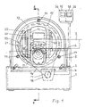
- a housing 2 is mounted in a height-adjustable manner in a base frame 1.
- the base frame 1 has sloping slots 3 into which stud bolts 4 connected to the housing 2 engage, the housing being clampable on the base frame 1 by means of toggle nuts 5.
- the base frame 1 has a support surface 6 for the workpiece 7, the corner 9 of which ends its side surface 8 is to be machined by a milling tool 10.
- the milling tool 10 can be driven by a milling motor 11 which is mounted on the housing 2 by means of two guide rods 12 in a pivoting member 13 so as to be pivotable about an axis parallel to the axis of the milling tool 10.
- the swivel member 13 is designed in the form of a guide ring, for the reception of which serve guide rollers 14 which are freely rotatably mounted on the housing 2.
- the swivel member 13 has a ring gear 15 with which a toothed chain 16 cooperates.
- this toothed chain 16 engages in a drive pinion 17 of a swivel motor 18 which is fixedly connected to the housing 2.
- a counterweight 19 is provided, which is also slidably mounted on a guide rod 20 in the swivel member 13. It is connected to the milling motor 11 by means of a wire rope 21 via deflection rollers 22 in such a way that it executes a movement opposite to this.
- a displacement unit 23 in the form of a compressed air cylinder is used to move the milling motor 11, and a feeler roller 24 is used to guide the milling tool 10 and is mounted on the milling motor 11 concentrically with the milling tool.
- an angle 25 is provided on which the feeler roller 24 is mounted so that it can be adjusted vertically with a screw 26 with differential thread and laterally with an eccentric 27.
- a sensing ring 28 is used, which is slidably connected to a slide 29 against the action of a spring 30.
- touch surface 31 can be adjusted with an adjusting screw 32 to the milling tool 10, an inclined contact surface 33 serves to move the touch ring 28 through the workpiece 7.
- a compressed-air-operated clamping device 34 which is connected to the base frame 1 and interacts with the support surface 6, serves to hold the workpiece 7 in place.
- a first control unit 35 which can be influenced by the swivel motor 18 and, depending on the desired angular position, causes the milling motor 11 to be placed on or off to control the displacement movement of the milling motor 11.
- the milling motor 11 is first guided around the corner 9 of the workpiece 7 with the contact roller 24 in contact.
- the corresponding angle values are displayed in a first display field 36 of the control unit 35.
- the corresponding angular positions are stored in the first control unit, so that the latter controls the displacement movement of the milling motor 11 during the subsequent milling work.
- the workpiece 7 has to be turned over after machining the first corner and inserted into the profiling device in such a way that the upper side of the workpiece 7 has been pointing downwards.
- a limit switch 37 is actuated by the workpiece 7, with the result that a second control unit 38 is activated. This causes reprogramming so that the program is adapted to the reverse contour.
- the limit switch 37 is mounted on the base frame 1 so that it can be moved and locked.
- the profiling device 39 is connected to a slide 41, which is slidably mounted on guide rods 42 of the edge banding machine 40.
- the profiling device 39 is carried along and controlled by the side surfaces 43 of the continuous workpiece 44 such that the milling tool (10) completely bypasses the workpiece 44 and thereby profiles the longitudinal edges and corners of workpiece 44.
- the milling tool connected to the milling motor 11 is again controlled with a feeler roller 24.
Landscapes
- Engineering & Computer Science (AREA)
- Mechanical Engineering (AREA)
- Life Sciences & Earth Sciences (AREA)
- Wood Science & Technology (AREA)
- Forests & Forestry (AREA)
- Milling Processes (AREA)
- Shaping Of Tube Ends By Bending Or Straightening (AREA)
- Milling, Drilling, And Turning Of Wood (AREA)
Abstract
Description
- Die Erfindung bezieht sich auf eine Profiliervorrichtung für Ecken gemäß Oberbegriff von Anspruch 1.
- Zum Profilieren an Ecken von plattenförmigen Werkstücken, deren Seitenflächen im allgemeinen mit Umleimern versehen sind, ist es bekannt, den Fräsmotor mit dem Fräswerkzeug auf einem in drei zueinander senkrechten Richtungen beweglichen Kreuzschlitten zu lagern und den Fräsmotor mittels Druckluftzylinder gegen das Werkstück zu verschieben. Mit dem Fräsmotor verbundene Tastrollen führen dabei das Werkzeug von der Oberseite des plattenförmigen Werkstücks über die Seitenflache bis zur Unterseite. Weist nun die Seitenfläche eine unregelmäßige und unsymetrische Kontur auf, so ist es sehr schwierig, das Werkzeug mittels der verschiedenen Druckluftzylinder so zu steuern, daß ein einwandfreies Fräsbild entsteht. Diese Steuerung erfolgt über die genaue Einstellung der Zylinder und von Drosseln, was mit einem erheblichen Zeitaufwand verbunden ist.
- Aufgabe der vorliegenden Erfindung ist daher die Schaffung einer Profiliervorrichtung der eingangs genannten Art, mit der die Ecken von plattenförmigen Werkstücken auch bei unregelmäßigem und unsymetrischem Querschnitt der Seitenflächen einwandfrei bearbeitbar sind, wobei sich die Vorrichtung rasch und sicher auf jeden gewünschten Querschnitt einstellen läßt.
- Die Aufgabe wird erfindungsgemäß durch das im kennzeichnenden Teil des Anspruchs 1 angegebenen Merkmal gelöst.
- Durch die schwenkbare Lagerung des Fräsmotors am Gehäuse wird das Fräswerkzeug von der Plattenoberseite über die Seitenfläche zur Unterseite verschwenkt, wobei der Fräsmotor in allen Winkelstellungen radial gegen das Werkstück gedrückt wird. Dabei ergibt sich ein gleichmäßiger Anpreßdruck für das Fräswerkzeug und ein einwandfreies Fräsbild bei beliebigen Konturen der Seitenflächen.
- Wird als Schwenkorgan erfindungsgemäß ein Ring verwendet, so läßt sich der Fräsmotor einfach und sicher innerhalb des Rings an Führungsstangen verschiebbar lagern. Ein gegenläufig zum Fräsmotor bewegbares Gegengewicht wirkt dem Gewicht des Fräsmotors entgegen, so daß in allen Winkelstellungen die gleiche Anpreßkraft gewährleistet ist.
- Das Gehäuse, an dem das Schwenkorgan befestigt ist, läßt sich gegen ein Untergestell mit Auflageflächen für das Werkstück in Höhenrichtung verschieben. Damit ist es möglich, den Mittelpunkt des Schwenkorgans so einzustellen, daß er in der Mitte des Werkstücks und um die halbe Werkstückdicke von dessen vorderer Seitenfläche entfernt liegt. Damit ist wieder ein optimaler Angriff des Fräswerkzeugs am Werkstück gewährleistet.
- Zur Steuerung der Profilierungsvorrichtung ist erfindungsgemäß eine Steuereinheit vorgesehen, die das Verschieben des Fräsmotors gegen das Werkstück und dessen Abheben steuert und einen raschen und sicheren Fräsvorgang gewährleistet.
- Ist die Ecke eines plattenförmigen Werkstücks mit unsymetrischer Seitenfläche zu bearbeiten, dann muß das Werkstück nach Bearbeiten der ersten Ecke umgeschlagen werden, d.h. die seitherige Oberseite des Werkstücks liegt jetzt unten. Die zweite Ecke weist jetzt im eingelegten Zustand einen umgekehrten Verlauf der Kontur auf, so daß ein Endschalter vorgesehen ist, der eine zweite Steuereinheit aktiviert, so daß das Programm der umgekehrten Kontur angepaßt wird.
- Die erfindungsgemäße Profiliervorrichtung kann sowohl als selbständige Einheit neben einer einfachen Kantenanleimmaschine benützt werden, es ist jedoch auch möglich, die Profiliervorrichtung direkt an eine Kantenanleimmaschine anzubringen.
- In diesem Fall ist sie auf einem Schlitten angeordnet, der in Vorschubvorrichtung der Werkstücke bewegbar ist und durch diese mitgenommen wird.
- Während des Durchlaufs kann dabei das Fräswerkzeug entlang einer Seitenfläche um das ganze Werkzeug so herumgeführt werden, daß sowohl die Längskanten der Seitenfläche als auch deren Ecken profiliert werden.
- Im folgenden sind Ausführungsbeispiele der Erfindung unter Bezugnahme auf die Zeichnungen näher beschrieben.
- Es zeigen:
- Fig. 1 Profiliervorrichtung, Ansicht von vorne, ohne Klemmvorrichtung
- Fig. 2 Profiliervorrichtung, Schnitt nach Linie II-II in Fig. 1
- Fig. 3 Kantenanleimmaschine mit Profiliervorrichtung, Ansicht von hinten
- Wie Fig. 1 zeigt, ist in einem Untergestell 1 ein Gehäuse 2 höhenverschiebbar gelagert. Dazu weist das Untergestell 1 geneigt verlaufende Schlitze 3 auf, in die mit dem Gehäuse 2 verbundene Stehbolzen 4 eingreifen, wobei das Gehäuse durch Knebelmuttern 5 am Untergestell 1 anklemmbar ist.
- Das Untergestell 1 weist eine Auflagefläche 6 für das Werkstück 7 auf, dessen seine Seitenfläche 8 abschließende Ecke 9 von einem Fräswerkzeug 10 bearbeitet werden soll.
- Wie auch Fig. 2 zeigt, ist das Fräswerkzeug 10 von einem Fräsmotor 11 antreibbar, der mittels zweier Führungsstangen 12 in einem Schwenkorgan 13 um eine zur Achse des Fräswerkzeugs 10 parallelen Achse schwenkbar am Gehäuse 2 gelagert ist.
- Das Schwenkorgan 13 ist in Form eines Führungsringes ausgebildet, zu dessen Aufnahme Führungsrollen 14 dienen, die am Gehäuse 2 frei drehbar gelagert sind.
- Das Schwenkorgan 13 weist einen Zahnkranz 15 auf, mit dem eine Zahnkette 16 zusammenwirkt. Diese Zahnkette 16 greift andererseits in ein Antriebsritzel 17 eines Schwenkmotors 18 ein, der mit dem Gehäuse 2 fest verbunden ist.
- Zum Ausgleich des Gewichts des Fräsmotors 11 ist ein Gegengewicht 19 vorgesehen, das ebenfalls an einer Führungsstange 20 verschiebbar im Schwenkorgan 13 gelagert ist. Es ist mit einem Drahtseil 21 über Umlenkrollen 22 so mit dem Fräsmotor 11 verbunden, daß es eine zu diesem gegenläufige Bewegung ausführt.
- Zum Verschieben des Fräsmotors 11 dient ein Verschiebeaggregat 23 in Form eines Druckluftzylinders, zur Führung des Fräswerkzeuges 10 dient eine Tastrolle 24, die konzentrisch zum Fräswerkzeug am Fräsmotor 11 gelagert ist. Für diese Lagerung ist ein Winkel 25 vorgesehen an dem die Tastrolle 24 in Höhenrichtung mit einer Schraube 26 mit Differenzgewinde und seitlich mit einem Excenter 27 einstellbar gelagert ist.
- Für die seitliche Tastung von Werkstück 7 dient ein Tastring 28, der mit einem Schlitten 29 gegen Wirkung einer Feder 30 verschiebbar verbunden ist.
- Seine Tastfläche 31 läßt sich mit einer Verstellschraube 32 zum Fräswerkzeug 10 einstellen, eine schräge Anlauffläche 33 dient zum Verschieben des Tastrings 28 durch das Werkstück 7.
- Zum Festhalten von Werkstück 7 dient eine druckluftbetriebene Klemmvorrichtung 34, die mit dem Untergestell 1 verbunden ist und mit der Auflagefläche 6 zusammenwirkt.
- Zur Steuerung der Verschiebebewegung von Fräsmotor 11 dient eine erste Steuereinheit 35, die vom Schwenkmotor 18 beeinflußbar ist und je nach gewünschter Winkelstellung ein Aufsetzen oder Abheben des Fräsmotors 11 bewirkt. Dazu wird zunächst der Fräsmotor 11 mit anliegender Tastrolle 24 um die Ecke 9 von Werkstück 7 herumgeführt. Die entsprechenden Winkelwerte werden dabei in einem ersten Anzeigenfeld 36 der Steuereinheit 35 angezeigt. Durch Betätigung eines Bedienungsknopfes werden die entsprechenden Winkelstellungen in der ersten Steuereinheit eingespeichert, so daß diese bei den folgenden Fräsarbeiten die Verschiebebewegung von Fräsmotor 11 steuert.
- Bei Seitenflächen 8 mit unsymetrischer Kontur muß das Werkstück 7 nach Bearbeitung der ersten Ecke umgeschlagen und so in die Profiliervorrichtung eingelegt werden, daß die seitherige Oberseite des Werkstücks 7 nach unten zeigt. Dabei wird in bestimmten Fällen ein Endschalter 37 vom Werkstück 7 betätigt, was zur Folge hat, daß eine zweite Steuereinheit 38 aktiviert wird. Diese bewirkt eine Umprogrammierung, so daß das Programm der umgekehrten Kontur angepaßt wird.
- Zur Anpassung von Endschalter 37 an die verschiedenen Konturen der Seitenflächen ist dieser am Untergestell 1 verschiebbar und feststellbar gelagert.
- Wie Fig. 3 zeigt, ist es auch möglich, die Profiliervorrichtung 39 an einer Kantenanleimmaschine 40 anzuordnen. Die Profiliervorrichtung 39 ist dazu mit einem Schlitten 41 verbunden, der an Führungsstangen 42 der Kantenanleimmaschine 40 verschiebbar gelagert ist. Durch die Seitenflächen 43 des durchlaufenden Werkstücks 44 wird die Profiliervorrichtung 39 so mitgenommen und gesteuert, daß das Fräswerkzeug (10) das Werkstück 44 vollkommen umfährt und dabei die Längskanten und Ecken von Werkstück 44 profiliert. Das mit dem Fräsmotor 11 verbundene Fräswerkzeug wird dabei wieder mit einer Tastrolle 24 gesteuert.
Claims (12)
Priority Applications (2)
| Application Number | Priority Date | Filing Date | Title |
|---|---|---|---|
| AT90107743T ATE91447T1 (de) | 1989-04-29 | 1990-04-24 | Profiliervorrichtung fuer ecken an plattenfoermigen werkstuecken. |
| DE9007738U DE9007738U1 (de) | 1989-04-29 | 1990-04-24 | Profiliervorrichtung für Ecken an plattenförmigen Werkstücken |
Applications Claiming Priority (2)
| Application Number | Priority Date | Filing Date | Title |
|---|---|---|---|
| DE3914353A DE3914353A1 (de) | 1989-04-29 | 1989-04-29 | Profiliervorrichtung fuer ecken an plattenfoermigen werkstuecken |
| DE3914353 | 1989-04-29 |
Publications (3)
| Publication Number | Publication Date |
|---|---|
| EP0395996A2 true EP0395996A2 (de) | 1990-11-07 |
| EP0395996A3 EP0395996A3 (de) | 1991-05-02 |
| EP0395996B1 EP0395996B1 (de) | 1993-07-14 |
Family
ID=6379850
Family Applications (1)
| Application Number | Title | Priority Date | Filing Date |
|---|---|---|---|
| EP90107743A Expired - Lifetime EP0395996B1 (de) | 1989-04-29 | 1990-04-24 | Profiliervorrichtung für Ecken an plattenförmigen Werkstücken |
Country Status (3)
| Country | Link |
|---|---|
| EP (1) | EP0395996B1 (de) |
| AT (1) | ATE91447T1 (de) |
| DE (2) | DE3914353A1 (de) |
Cited By (8)
| Publication number | Priority date | Publication date | Assignee | Title |
|---|---|---|---|---|
| EP0602308A1 (de) * | 1992-12-18 | 1994-06-22 | Homag Maschinenbau Ag | Vorrichtung zur Bearbeitung der Kantenränder von fortlaufend bewegten plattenförmigen Werkstücken |
| ES2053368A2 (es) * | 1992-01-08 | 1994-07-16 | Construcciones P B R S A | Perfeccionamientos en maquinas perfiladoras de cantos con forma. |
| DE4408596A1 (de) * | 1994-03-15 | 1995-09-21 | Reich Spezialmaschinen Gmbh | Kantenanleimmaschine mit einer Fräsvorrichtung |
| EP0911100A2 (de) * | 1997-10-22 | 1999-04-28 | Fravol Export S.r.l. | Werkzeug zur Bearbeitung von Plattenkanten und damit ausgerüstete Maschine |
| EP1302287A2 (de) * | 2001-10-12 | 2003-04-16 | BIESSE S.p.A. | Vorrichtung zur Bearbeitung von Holzpaneelen oder dergleichen |
| EP2392438A1 (de) * | 2010-06-02 | 2011-12-07 | Homag Holzbearbeitungssysteme AG | Bearbeitungsvorrichtung |
| EP2689903A1 (de) | 2012-07-23 | 2014-01-29 | SCM Group Tecmatic Maquinas e Equipamentos Ltda | Abrundungs- und Beschneidungsgruppe für Kanten von Platten |
| WO2019058055A1 (fr) * | 2017-09-20 | 2019-03-28 | Eurl Usiplace 39 | Dispositif de rectification et procédé |
Citations (3)
| Publication number | Priority date | Publication date | Assignee | Title |
|---|---|---|---|---|
| JPS58109260A (ja) * | 1981-12-22 | 1983-06-29 | Nippon Sheet Glass Co Ltd | 異形ワ−ク研削・研磨用汎用機 |
| EP0086283A1 (de) * | 1982-02-11 | 1983-08-24 | Firma Ernst Baumgartner | Kantenbrechmaschine |
| US4787786A (en) * | 1987-08-24 | 1988-11-29 | Freud Ivan B | Laminate cutting device |
-
1989
- 1989-04-29 DE DE3914353A patent/DE3914353A1/de not_active Withdrawn
-
1990
- 1990-04-24 AT AT90107743T patent/ATE91447T1/de not_active IP Right Cessation
- 1990-04-24 DE DE9090107743T patent/DE59001944D1/de not_active Expired - Fee Related
- 1990-04-24 EP EP90107743A patent/EP0395996B1/de not_active Expired - Lifetime
Patent Citations (3)
| Publication number | Priority date | Publication date | Assignee | Title |
|---|---|---|---|---|
| JPS58109260A (ja) * | 1981-12-22 | 1983-06-29 | Nippon Sheet Glass Co Ltd | 異形ワ−ク研削・研磨用汎用機 |
| EP0086283A1 (de) * | 1982-02-11 | 1983-08-24 | Firma Ernst Baumgartner | Kantenbrechmaschine |
| US4787786A (en) * | 1987-08-24 | 1988-11-29 | Freud Ivan B | Laminate cutting device |
Non-Patent Citations (1)
| Title |
|---|
| PATENT ABSTRACTS OF JAPAN vol. 7, no. 215 (M-244)(1360) 22 September 1983, & JP-A-58 109260 (NIHON ITA GLASS K.K.) 29 Juni 1983, * |
Cited By (11)
| Publication number | Priority date | Publication date | Assignee | Title |
|---|---|---|---|---|
| ES2053368A2 (es) * | 1992-01-08 | 1994-07-16 | Construcciones P B R S A | Perfeccionamientos en maquinas perfiladoras de cantos con forma. |
| EP0602308A1 (de) * | 1992-12-18 | 1994-06-22 | Homag Maschinenbau Ag | Vorrichtung zur Bearbeitung der Kantenränder von fortlaufend bewegten plattenförmigen Werkstücken |
| DE4408596A1 (de) * | 1994-03-15 | 1995-09-21 | Reich Spezialmaschinen Gmbh | Kantenanleimmaschine mit einer Fräsvorrichtung |
| US5803682A (en) * | 1994-03-15 | 1998-09-08 | Reich Spezialmaschinen Gmbh | Edge milling device |
| EP0911100A2 (de) * | 1997-10-22 | 1999-04-28 | Fravol Export S.r.l. | Werkzeug zur Bearbeitung von Plattenkanten und damit ausgerüstete Maschine |
| EP0911100A3 (de) * | 1997-10-22 | 2004-03-31 | Fravol Export S.r.l. | Werkzeug zur Bearbeitung von Plattenkanten und damit ausgerüstete Maschine |
| EP1302287A2 (de) * | 2001-10-12 | 2003-04-16 | BIESSE S.p.A. | Vorrichtung zur Bearbeitung von Holzpaneelen oder dergleichen |
| EP1302287A3 (de) * | 2001-10-12 | 2003-10-01 | BIESSE S.p.A. | Vorrichtung zur Bearbeitung von Holzpaneelen oder dergleichen |
| EP2392438A1 (de) * | 2010-06-02 | 2011-12-07 | Homag Holzbearbeitungssysteme AG | Bearbeitungsvorrichtung |
| EP2689903A1 (de) | 2012-07-23 | 2014-01-29 | SCM Group Tecmatic Maquinas e Equipamentos Ltda | Abrundungs- und Beschneidungsgruppe für Kanten von Platten |
| WO2019058055A1 (fr) * | 2017-09-20 | 2019-03-28 | Eurl Usiplace 39 | Dispositif de rectification et procédé |
Also Published As
| Publication number | Publication date |
|---|---|
| DE59001944D1 (de) | 1993-08-19 |
| DE3914353A1 (de) | 1990-10-31 |
| ATE91447T1 (de) | 1993-07-15 |
| EP0395996A3 (de) | 1991-05-02 |
| EP0395996B1 (de) | 1993-07-14 |
Similar Documents
| Publication | Publication Date | Title |
|---|---|---|
| EP0229668A2 (de) | Schneidmaschine für plattenförmige Werkstücke | |
| DE3035962C3 (de) | Vorrichtung zum Steuern der Antriebe einer Bandsägemaschine | |
| DE2225197C3 (de) | Maschine zum Sägen langer Werkstücke mit vertikalem Vorschub des Sägeblatts | |
| EP0395996B1 (de) | Profiliervorrichtung für Ecken an plattenförmigen Werkstücken | |
| EP1136206B1 (de) | Schwenkfräsmaschine | |
| EP3969217B1 (de) | Quertisch für eine holzbearbeitungsmaschine und holzbearbeitungsmaschine mit einem derartigen quertisch, sowie verfahren zur steurung einer holzbearbeitungsmaschine | |
| EP0330970A2 (de) | Vorrichtung zum Positionieren von bogenförmigen Kreuzsprossenrahmenteilen und zum Fräsen von trapezförmigen Ausnehmungen in diese Rahmenteile | |
| AT390025B (de) | Vorrichtung zum herstellen prismatischer oder pyramidenstumpffoermiger balken | |
| DE1453213C3 (de) | ||
| EP0654333A1 (de) | Maschine zum Bearbeiten von Werkstücken aus Holz, Kunststoff und dergleichen | |
| DE1502888B2 (de) | ||
| DE3831378C2 (de) | Anschlagvorrichtung für Tischsägen | |
| DE3817833C2 (de) | ||
| DE4409813C2 (de) | Vorrichtung zum Zuschneiden von stabförmigen Werkstücken, insbesondere von Glassprossen für Fenster oder Türen | |
| DE3422101C2 (de) | ||
| EP0167112B1 (de) | Verfahren und Vorrichtung zum Fräsen und Nuten von Rahmenteilen aus Holz | |
| DE2928108A1 (de) | Einseitige duebelloch-bohrmaschine | |
| DE3915855C2 (de) | ||
| DE4326890A1 (de) | Vorrichtung zum Schleifen der Kanten von platten- oder tafelförmigen Werkstücken | |
| DE1899578U (de) | Vorrichtung zum bearbeiten von werkstuecken, insbesondere kantenfurnierten werkstuecken. | |
| DE3621228C2 (de) | ||
| EP1195222A2 (de) | Vorrichtung zum Fräsen von Kreisbogen | |
| DE3508496A1 (de) | Handgefuehrte vorrichtung zum profilfraesen an werkstuecken aus holz, insbesondere an handlaeufen fuer treppengelaender | |
| DE4128072A1 (de) | Saege | |
| DE2614107A1 (de) | Fuehrungsbuechse fuer werkzeuge |
Legal Events
| Date | Code | Title | Description |
|---|---|---|---|
| PUAI | Public reference made under article 153(3) epc to a published international application that has entered the european phase |
Free format text: ORIGINAL CODE: 0009012 |
|
| AK | Designated contracting states |
Kind code of ref document: A2 Designated state(s): AT BE CH DE FR GB IT LI NL SE |
|
| PUAL | Search report despatched |
Free format text: ORIGINAL CODE: 0009013 |
|
| AK | Designated contracting states |
Kind code of ref document: A3 Designated state(s): AT BE CH DE FR GB IT LI NL SE |
|
| 17P | Request for examination filed |
Effective date: 19910720 |
|
| 17Q | First examination report despatched |
Effective date: 19921125 |
|
| GRAA | (expected) grant |
Free format text: ORIGINAL CODE: 0009210 |
|
| AK | Designated contracting states |
Kind code of ref document: B1 Designated state(s): AT BE CH DE FR GB IT LI NL SE |
|
| REF | Corresponds to: |
Ref document number: 91447 Country of ref document: AT Date of ref document: 19930715 Kind code of ref document: T |
|
| REF | Corresponds to: |
Ref document number: 59001944 Country of ref document: DE Date of ref document: 19930819 |
|
| ITF | It: translation for a ep patent filed |
Owner name: ING. C. GREGORJ S.P.A. |
|
| ET | Fr: translation filed | ||
| GBT | Gb: translation of ep patent filed (gb section 77(6)(a)/1977) |
Effective date: 19931022 |
|
| PLBI | Opposition filed |
Free format text: ORIGINAL CODE: 0009260 |
|
| PLBI | Opposition filed |
Free format text: ORIGINAL CODE: 0009260 |
|
| 26 | Opposition filed |
Opponent name: HANS KNOLL ENGINEERING Effective date: 19940405 |
|
| 26 | Opposition filed |
Opponent name: IDM INTERNATIONAL S.R.L. Effective date: 19940413 Opponent name: HANS KNOLL ENGINEERING Effective date: 19940405 |
|
| NLR1 | Nl: opposition has been filed with the epo |
Opponent name: HANS KNOLL ENGINEERING. |
|
| NLR1 | Nl: opposition has been filed with the epo |
Opponent name: IDM INTERNATIONAL S.R.L. |
|
| EAL | Se: european patent in force in sweden |
Ref document number: 90107743.8 |
|
| PLAW | Interlocutory decision in opposition |
Free format text: ORIGINAL CODE: EPIDOS IDOP |
|
| APAC | Appeal dossier modified |
Free format text: ORIGINAL CODE: EPIDOS NOAPO |
|
| APAE | Appeal reference modified |
Free format text: ORIGINAL CODE: EPIDOS REFNO |
|
| APAC | Appeal dossier modified |
Free format text: ORIGINAL CODE: EPIDOS NOAPO |
|
| APAE | Appeal reference modified |
Free format text: ORIGINAL CODE: EPIDOS REFNO |
|
| PLAB | Opposition data, opponent's data or that of the opponent's representative modified |
Free format text: ORIGINAL CODE: 0009299OPPO |
|
| R26 | Opposition filed (corrected) |
Opponent name: HANS KNOLL ENGINEERING * 19940413 IDM INTERNATIONA Effective date: 19940405 |
|
| APAC | Appeal dossier modified |
Free format text: ORIGINAL CODE: EPIDOS NOAPO |
|
| NLR1 | Nl: opposition has been filed with the epo |
Opponent name: IDM INTERNATIONAL S.R.L. Opponent name: HANS KNOLL ENGINEERING |
|
| PLAW | Interlocutory decision in opposition |
Free format text: ORIGINAL CODE: EPIDOS IDOP |
|
| PLAW | Interlocutory decision in opposition |
Free format text: ORIGINAL CODE: EPIDOS IDOP |
|
| PLBO | Opposition rejected |
Free format text: ORIGINAL CODE: EPIDOS REJO |
|
| PLBN | Opposition rejected |
Free format text: ORIGINAL CODE: 0009273 |
|
| STAA | Information on the status of an ep patent application or granted ep patent |
Free format text: STATUS: OPPOSITION REJECTED |
|
| 27O | Opposition rejected |
Effective date: 20000923 |
|
| NLR2 | Nl: decision of opposition | ||
| REG | Reference to a national code |
Ref country code: GB Ref legal event code: IF02 |
|
| APAH | Appeal reference modified |
Free format text: ORIGINAL CODE: EPIDOSCREFNO |
|
| PGFP | Annual fee paid to national office [announced via postgrant information from national office to epo] |
Ref country code: FR Payment date: 20060414 Year of fee payment: 17 |
|
| PGFP | Annual fee paid to national office [announced via postgrant information from national office to epo] |
Ref country code: BE Payment date: 20070205 Year of fee payment: 18 |
|
| PGFP | Annual fee paid to national office [announced via postgrant information from national office to epo] |
Ref country code: SE Payment date: 20070412 Year of fee payment: 18 |
|
| PGFP | Annual fee paid to national office [announced via postgrant information from national office to epo] |
Ref country code: NL Payment date: 20070427 Year of fee payment: 18 |
|
| PGFP | Annual fee paid to national office [announced via postgrant information from national office to epo] |
Ref country code: CH Payment date: 20070509 Year of fee payment: 18 |
|
| REG | Reference to a national code |
Ref country code: CH Ref legal event code: PCAR Free format text: ISLER & PEDRAZZINI AG;POSTFACH 1772;8027 ZUERICH (CH) |
|
| PGFP | Annual fee paid to national office [announced via postgrant information from national office to epo] |
Ref country code: GB Payment date: 20070418 Year of fee payment: 18 |
|
| PGFP | Annual fee paid to national office [announced via postgrant information from national office to epo] |
Ref country code: DE Payment date: 20080606 Year of fee payment: 19 |
|
| PGFP | Annual fee paid to national office [announced via postgrant information from national office to epo] |
Ref country code: AT Payment date: 20080221 Year of fee payment: 19 |
|
| PGFP | Annual fee paid to national office [announced via postgrant information from national office to epo] |
Ref country code: IT Payment date: 20080423 Year of fee payment: 19 |
|
| BERE | Be: lapsed |
Owner name: *REICH SPEZIALMASCHINEN G.M.B.H. Effective date: 20080430 |
|
| REG | Reference to a national code |
Ref country code: CH Ref legal event code: PL |
|
| EUG | Se: european patent has lapsed | ||
| GBPC | Gb: european patent ceased through non-payment of renewal fee |
Effective date: 20080424 |
|
| NLV4 | Nl: lapsed or anulled due to non-payment of the annual fee |
Effective date: 20081101 |
|
| PG25 | Lapsed in a contracting state [announced via postgrant information from national office to epo] |
Ref country code: LI Free format text: LAPSE BECAUSE OF NON-PAYMENT OF DUE FEES Effective date: 20080430 Ref country code: NL Free format text: LAPSE BECAUSE OF NON-PAYMENT OF DUE FEES Effective date: 20081101 Ref country code: CH Free format text: LAPSE BECAUSE OF NON-PAYMENT OF DUE FEES Effective date: 20080430 |
|
| REG | Reference to a national code |
Ref country code: FR Ref legal event code: ST Effective date: 20081231 |
|
| PG25 | Lapsed in a contracting state [announced via postgrant information from national office to epo] |
Ref country code: BE Free format text: LAPSE BECAUSE OF NON-PAYMENT OF DUE FEES Effective date: 20080430 |
|
| PG25 | Lapsed in a contracting state [announced via postgrant information from national office to epo] |
Ref country code: FR Free format text: LAPSE BECAUSE OF NON-PAYMENT OF DUE FEES Effective date: 20080430 |
|
| PG25 | Lapsed in a contracting state [announced via postgrant information from national office to epo] |
Ref country code: FR Free format text: LAPSE BECAUSE OF NON-PAYMENT OF DUE FEES Effective date: 20070430 |
|
| PG25 | Lapsed in a contracting state [announced via postgrant information from national office to epo] |
Ref country code: GB Free format text: LAPSE BECAUSE OF NON-PAYMENT OF DUE FEES Effective date: 20080424 |
|
| PLAB | Opposition data, opponent's data or that of the opponent's representative modified |
Free format text: ORIGINAL CODE: 0009299OPPO |
|
| PG25 | Lapsed in a contracting state [announced via postgrant information from national office to epo] |
Ref country code: DE Free format text: LAPSE BECAUSE OF NON-PAYMENT OF DUE FEES Effective date: 20091103 Ref country code: AT Free format text: LAPSE BECAUSE OF NON-PAYMENT OF DUE FEES Effective date: 20090424 |
|
| PG25 | Lapsed in a contracting state [announced via postgrant information from national office to epo] |
Ref country code: SE Free format text: LAPSE BECAUSE OF NON-PAYMENT OF DUE FEES Effective date: 20080425 |
|
| PG25 | Lapsed in a contracting state [announced via postgrant information from national office to epo] |
Ref country code: IT Free format text: LAPSE BECAUSE OF NON-PAYMENT OF DUE FEES Effective date: 20090424 |