EP0394941A2 - Circuit d'attaque pour un moteur pas à pas - Google Patents
Circuit d'attaque pour un moteur pas à pas Download PDFInfo
- Publication number
- EP0394941A2 EP0394941A2 EP90107700A EP90107700A EP0394941A2 EP 0394941 A2 EP0394941 A2 EP 0394941A2 EP 90107700 A EP90107700 A EP 90107700A EP 90107700 A EP90107700 A EP 90107700A EP 0394941 A2 EP0394941 A2 EP 0394941A2
- Authority
- EP
- European Patent Office
- Prior art keywords
- current
- constant
- circuit
- exciting
- stepping motor
- Prior art date
- Legal status (The legal status is an assumption and is not a legal conclusion. Google has not performed a legal analysis and makes no representation as to the accuracy of the status listed.)
- Granted
Links
- 238000006073 displacement reaction Methods 0.000 description 6
- 238000000034 method Methods 0.000 description 6
- 230000008569 process Effects 0.000 description 6
- 230000005284 excitation Effects 0.000 description 4
- 238000010586 diagram Methods 0.000 description 3
- 230000008859 change Effects 0.000 description 2
- 230000005484 gravity Effects 0.000 description 2
- 238000012986 modification Methods 0.000 description 2
- 230000004048 modification Effects 0.000 description 2
- 230000002457 bidirectional effect Effects 0.000 description 1
- 230000002950 deficient Effects 0.000 description 1
- 230000006872 improvement Effects 0.000 description 1
- 230000007257 malfunction Effects 0.000 description 1
- 230000003405 preventing effect Effects 0.000 description 1
- 230000009467 reduction Effects 0.000 description 1
Images


Classifications
-
- G—PHYSICS
- G11—INFORMATION STORAGE
- G11B—INFORMATION STORAGE BASED ON RELATIVE MOVEMENT BETWEEN RECORD CARRIER AND TRANSDUCER
- G11B5/00—Recording by magnetisation or demagnetisation of a record carrier; Reproducing by magnetic means; Record carriers therefor
- G11B5/02—Recording, reproducing, or erasing methods; Read, write or erase circuits therefor
- G11B5/022—H-Bridge head driver circuit, the "H" configuration allowing to inverse the current direction in the head
-
- H—ELECTRICITY
- H02—GENERATION; CONVERSION OR DISTRIBUTION OF ELECTRIC POWER
- H02P—CONTROL OR REGULATION OF ELECTRIC MOTORS, ELECTRIC GENERATORS OR DYNAMO-ELECTRIC CONVERTERS; CONTROLLING TRANSFORMERS, REACTORS OR CHOKE COILS
- H02P8/00—Arrangements for controlling dynamo-electric motors rotating step by step
- H02P8/12—Control or stabilisation of current
-
- G—PHYSICS
- G11—INFORMATION STORAGE
- G11B—INFORMATION STORAGE BASED ON RELATIVE MOVEMENT BETWEEN RECORD CARRIER AND TRANSDUCER
- G11B5/00—Recording by magnetisation or demagnetisation of a record carrier; Reproducing by magnetic means; Record carriers therefor
- G11B5/48—Disposition or mounting of heads or head supports relative to record carriers ; arrangements of heads, e.g. for scanning the record carrier to increase the relative speed
- G11B5/54—Disposition or mounting of heads or head supports relative to record carriers ; arrangements of heads, e.g. for scanning the record carrier to increase the relative speed with provision for moving the head into or out of its operative position or across tracks
- G11B5/55—Track change, selection or acquisition by displacement of the head
- G11B5/5521—Track change, selection or acquisition by displacement of the head across disk tracks
- G11B5/5526—Control therefor; circuits, track configurations or relative disposition of servo-information transducers and servo-information tracks for control thereof
Definitions
- the present invention relates to a drive circuit for a stepping motor and, more particularly, to a drive circuit for a stepping motor which is capable of setting the exciting current to be supplied to each exciting coil at the optimum value.
- a stepping motor has hitherto been used in equipments such as a floppy disk drive (hereinunder referred to as "FDD") so as to obtain a necessary rotational angle. More specifically, in order to write or read necessary data by the access to a given track on a floppy disk, for example, it is necessary to position the head for reading and writing in such a manner as to be settled to the predetermined track on the disk. At this time, the position of the predetermined track on the disk can be represented by the rotational angle of the stepping motor with respect to the reference position thereof. In order to position the head at a given rotational position of the stepping motor, a stepping motor having a necessary stepping angle is used.
- FDD floppy disk drive
- a stepping motor is composed of a rotor which rotates by the angle corresponding to the number of supplied pulses, and a plurality of exciting coils for generating excitation fields which act on the rotor.
- the stepping motor is driven by a drive circuit including a drive control circuit which supplies exciting currents to the exciting coils in correspondence with the pulse signals input from the outer host computer.
- a pulse signal is input from the outside of the motor and the circuit supplies a predetermined exciting current to the exciting coils.
- the rotor is rotated by the excitation fields generated on the exciting coils in correspondence with the exciting currents.
- an exciting current is supplied to each exciting coil so that a predetermined rotational angle (hereinunder referred to as "stepping angle") is provided for the rotor every time one pulse signal is input to the drive circuit.
- FIG. 7 shows the entire structure of a drive circuit for what is called four-phase two-coil type stepping motor.
- a drive circuit 10 is composed of a first exciting coil 14 and a second exciting coil for supplying magnetic excitation fields to a rotor 12, and a first drive control circuit 18 and a second drive control circuit 20 for supplying exciting currents I1 and I2 to the coils 14 and 16, respectively, in accordance with the pulse signals input from the outer host computer.
- the exciting currents I1 and I2 are respectively supplied so that the rotor 12 rotates by a predetermined stepping angle every time one pulse signal is input from the outer host computer.
- Fig. 8 is a circuit diagram of the first drive control circuit 18. Since the second drive control circuit 20 has a similar structure to that of the first drive control circuit 18, explanation of the structure of the second drive control circuit 20 will be omitted.
- the first drive control circuit 18 is connected to both ends of the first exciting coil 14 and includes a switching circuit 24 (124) for outputting a switching signal in accordance with the pulse signal input from the outer host computer and transistors 26 (126), 28 (128) to which a driving voltage V cc is applied from the outer host computer and which are turned on/off in accordance with an ON/OFF signal supplied from the switching circuit 24 (124).
- an ON signal is output from either of the switching circuits 24 and 124, and an OFF signal is output from the other switching circuit.
- an ON signal is output from the switching circuit 24 and an OFF signal is output from the switching circuit 124
- the transistors 26 and 28 are turned on and the transistors 126 and 128 are turned off.
- An exciting current I 1a flows on the exciting coil 14 by the application of the driving voltage V cc .
- the reverse exciting current I 1b flows on the exciting coil 14. In this way, according to the drive control circuit 18, it is possible to supply the exciting currents I 1a and I 1b to the exciting coil 14.
- Fig. 9 shows the operation of a stepping motor using the drive circuit 10 having the structure shown in Figs. 7 and 8.
- Fig. 9(a) shows a stepping motor in which exciting currents I1 and I2 flow on the exciting coils 14 and 16, respectively, so that the rotor 12 rotates clockwise. If the stepping angle ⁇ s is set at 45°, the angular displacement ⁇ from the reference radius upwardly extending from the center of the rotor 12 takes eight different values during one revolution of the rotor 12.
- Fig. 9(b) shows the relationship between the exciting currents I1, I2, the angular displacement ⁇ and the stepping angle ⁇ S , and the number of pulse signals supplied from the outer host computer to the drive circuit 10.
- the exciting currents I1, I2 flowing on the exciting coils 14 and 16 take predetermined values of I 1a and I 2b , respectively.
- the predetermined value I 1a is the value of an exciting current which is supplied to the exciting coil 14 when the transistors 26 and 28 are turned on in the first drive control circuit 18 shown in Fig. 8.
- the other predetermined value I 2b is also the value of an exciting current which is similarly supplied to the exciting coil 16 in the second drive control circuit 20 having the same structure as the first drive control circuit 18.
- the rotor 12 is rotated clockwise by the stepping angle ⁇ s by the exciting fields generated on the exciting coils 14 and 16 in accordance with the exciting currents I1 and I2.
- the exciting currents I1 and I2 take the value of ⁇ and the predetermined value I 2b , respectively and the rotor 12 further rotates by the stepping angle ⁇ S .
- the exciting currents I1 and I2 take the respective predetermined values I 1b and I 2b , and the rotor 12 further rotates by the stepping angle ⁇ S .
- the predetermined value I 1b is the value of an exciting current which is supplied to the exciting coil 14 when the transistors 126 and 128 are turned on in the first drive control circuit 18.
- the exciting current I 1b is a current flowing in the reverse direction to the exciting current I 1a .
- the drive circuit 10 it is possible to obtain a stepping motor which is capable of outputting the rotational angle by the unit of the stepping angle ⁇ S , if necessary, by displacing the rotational angle of the rotor 12 by the unit of the stepping angle ⁇ S in accordance with the pulse signal which is input from the outer host computer in series.
- the drive circuit for a conventional stepping motor having the above-described structure is disadvantageous in that nonuniformity in the resistances of the exciting coils or the like produces nonuniformity in the exciting currents supplied to the respective exciting coils, thereby producing an error in the stepping angle.
- the exciting currents have the following relationship due to nonuniformity, as shown in Fig. 9(b): I 1a ⁇ I 2b , I 1b ⁇ I 2a the nonuniformity in the exciting current produces a nonuniformity in the excitation fields and, hence, a nonuniformity in the gravities or repulsions.
- the stepping angle ⁇ S does not therefore agree with the desired stepping angle ⁇ S0 (45° in Fig. 9(b)) and takes a value ⁇ S0 + ⁇ 1 or ⁇ S0 - ⁇ 2 which contains a stepping angle error ⁇ 1 or ⁇ 2 caused by the nonuniformity in the exciting currents.
- Such a drive circuit for a stepping motor causes a malfunction or defective operation of the equipment such as an error in writing or reading in equipments such as an FDD.
- a drive circuit is characterized in that a constant-current circuit is provided for so controlling the currents supplied to the exciting coils as to have a constant value and set the exciting currents flowing on the respective exciting coils at the same value, thereby improving the accuracy of the stepping angle.
- the exciting currents flowing on the respective exciting coils are so controlled as to have the same value by the constant-current circuit. Therefore, the exciting fields generated on the exciting coils by the exciting currents become the same. In this way, the generation of an error in the stepping angle of the rotating rotor is prevented and the stepping angle is obtained with improved accuracy.
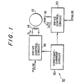
- Fig. 1 shows the entire structure of a first embodiment of a drive circuit for a four-phase two-coil stepping motor according to the present invention.
- the first and second drive control circuits 18 and 20 for supplying exciting currents to the first and second exciting coils 14 and 16 supply a constant current i0 to the respective exciting coils 14, 16 under the control of a constant-current circuit 30, which characterizes the present invention.
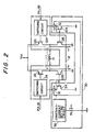
- the first drive control circuit 18 and the constant-current circuit 30, which characterizes the present invention have the structure shown in Fig. 2.
- the constant-current circuit 30 is composed of a constant-current source 32 (132) which is connected to the switching circuit 24 (124) from which an ON/OFF signal having the inverse value to the ON/OFF signal supplied to the transistor 26 (126) is supplied so that the current output is turned on/off, a transistor 34 (134) which is connected to the constant-current source 32 (132) and the base of which is connected to the base of the transistor 128 (28) so as to constitute a current mirror circuit, a constant-current setting circuit 36 for setting the output current i0 of the constant-current source 32 (132), and a monitor resistance R S which relates to the setting of the output current i0.
- the constant current i0 of the constant-current source 32 (132) is set by the constant-current setting circuit 36 so that the current i S which flows to the monitor resistance R S and i0 are proportional to each other.
- the constant current I0 is supplied to the transistor 34 (134), and the current mirror circuit constituted by the transistors 34 (134) and 128 (28) causes the current which flows to the transistor 128 (28) to have the same value as the constant current i0.
- the exciting current I1 supplied to the exciting coil 14 through the transistor 26 and the exciting current I1 supplied to the exciting coil 14 through the transistor 126 have the same absolute value. More specifically, when the transistor 26 is turned on in accordance with the ON signal from the switching circuit 24, the current output of the constant-current source 32 is turned off, the transistor 126 is turned off in accordance with the OFF signal from the switching circuit 124 and the current output of the constant-current source 132 is turned on, the transistors 26 and 28 are turned on and the exciting current I1 supplied to the exciting coil 14 takes the same value as the current flowing to the transistor 134, namely, the constant current i0 due to the current mirror circuit constituted by the transistors 28 and 134.
- the transistor 126 when the transistor 126 is turned on in accordance with the ON signal from the switching circuit 124, the current output of the constant-current source 132 is turned off, the transistor 26 is turned off in accordance with the OFF signal from the switching circuit 24 and the current output of the constant-current source 32 is turned on, the transistors 126 and 128 are turned on and the exciting current I1 supplied to the exciting coil 14 takes the same value as the current flowing to the transistor 34, namely, the constant current i0 due to the current mirror circuit constituted by the transistors 128 and 34.
- the exciting current I2 flowing on the second exciting coil 16 has the same value as the constant current i0 in the same way as the exciting current I1 flowing on the first exciting coil 14.
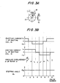
- the stepping angle ⁇ S agrees with the desired value ⁇ S0 (45° in Fig. 3). Since the exciting currents I1 and I2 supplied to the exciting coils 14 and 16 are bidirectional currents having the same value as the constant current i0 by virtue of the constant-current circuit 30, the exciting fields generated on the exciting coils 14 and 16 by the exciting currents I1 and I2 having the same value also have the same value. The gravities and the repulsions caused by the exciting coils 14 and 16 also have the same value, whereby the angular displacement ⁇ is produced on the rotor 12 by the unit of a desired stepping angle ⁇ S0 .
- the exciting currents are caused to have the same value by the constant-current circuit 30, no error caused by the nonuniformity in the exciting currents is contained in the stepping angle ⁇ S , whereby it is possible to control the rotation of the rotor 12 and achieve the improvement of the accuracy of the stepping angle of the stepping motor.
- Fig. 4 shows a second embodiment of the present invention.
- the same numerals are provided for the elements which are the same as those in the first embodiment shown in Fig. 2, and explanation thereof will be omitted.
- the second embodiment is characterized in that a constant-current circuit 230 sets different constant current values in accordance with the stage of step seeking.
- the fixed resistance R S attached to the constant-current setting circuit 36 is varied in accordance with the state of step seeking.
- different resistances are represented by a plurality of resistances Ra, Rb1, Rb2, Rb3, Rc and Rd having different values selected in advance.
- the resistance Ra determines the starting current applied when a seek command is supplied to the stepping motor and the resistances Rb1 to Rb3 respectively determine the currents necessary at the time of seeking after starting with respect to different stepping rates of step pulses, as will be described later in detail.
- the resistance Rc determines the current applied at the time of settling for positioning the read/write head at a predetermined track, and the resistance Rd determines hold current applied at the time of reading/writing.
- transistors 201 to 206 are connected to the respective resistances, and a base current is supplied from a control circuit 210 to the base of each transistor, so that only the selected transistor is turned on and the resistance connected to the selected transistor determines the current value of the constant-current setting circuit 36.
- a step pulse is supplied and a signal for selectively switching each transistor is output from the control circuit 210.
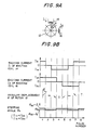
- Fig. 5 shows an example of a change in the average driving current due to a change in the constant current at the time of application of a step pulse and the movement of the head.
- the step pulse is composed of a train of seven pulses having the standard pulse rate, which is set at 4 to 5 ms.
- the step pulse is shown in Fig. 5(A), and the average current is selected in accordance with the movement of the head in this embodiment, as shown in Fig. 5(B).
- the selection of the average current is determined by the selection of a resistance from the resistances Ra to Rd in Fig. 4.
- Fig. 5(C) shows an example of the movement of the head, wherein the abscissa represents the elapse of time and the ordinate the position of the track.
- the abscissa represents the elapse of time and the ordinate the position of the track.
- the movement of the head is divided into five stages.
- a comparatively large current is applied, and the starting current is generated by the resistance Ra shown in Fig. 4.
- the starting stage is defined by a predetermined time Ta elapsed from the application of the first pulse.
- the starting time Ta takes a constant value irrespective of the variation of the stepping rate, but the starting time may naturally be changed as desired in the present invention.
- the process moves to the actual seeking operation.
- the average current is preferably set at the minimum current necessary for seeking the head, thereby enabling great reduction in the current consumed.
- the current applied at the seeking stage Tb1 is determined by the resistance Rb1 shown in Fig. 4, and the current at the seeking stage varies in accordance with the stepping rate.
- the settling stage is set as the third stage in order to determine the actual position with accuracy.
- a comparatively large current is supplied again in the same way as at the time of starting, the current value at this time being determined by the resistance Rc shown in Fig. 4.
- the current applied at the time of settling is set at a constant value irrespective of the stepping rate, whereby the head is positioned at the correct position with an overshoot.
- the process proceeds to the holding stage Td as the fourth stage in order to hold the position of the head.
- a small average current is supplied to the stepping motor. The average current at this time is determined by the resistance Rd shown in Fig. 4.
- the head carries out the reading or writing operation.
- the average current is set at a different value on the basis of the difference in the stepping rate by changing over the resistance to any of the resistances Rb1, Rb2 and Rb3, as shown in Fig. 5(B).
- Fig. 6 shows the operation of the control circuit 210 for switching the resistances so as to switch the average currents shown in Fig. 5(B) in the following manner.
- the supply of a step pulse is waited for, and when a step pulse is applied, the base current is supplied from the control circuit 210 to a transistor 201 at the step 302, whereby the fixed resistance Ra is selected as the resistance of the constant-current setting circuit 36.
- the stepping rate T is measured at the step 303, and the measured stepping rate T is stored.
- the supply of the starting current is continued for the predetermined time Ta from the application of the first step pulse, and the duration is monitored at the step 304.
- the supply of the comparatively large current at the time of starting is continued for the predetermined time Ta irrespective of the stepping rate, and for example, when the stepping rate is standard or high, two step pulses are supplied during the starting period, while when the stepping rate is low, one step pulse is counted.
- the standard stepping rate is about 4 to 5 ms, as described above, and the low stepping rate is set at about 6 ms, while the high stepping rate is set at about 3 ms.
- the process proceeds from the step 305 to the step 308 at which the base current is supplied from the control circuit 210 to a transistor 203 so as to select the resistance Rb2 for obtaining a comparatively large current value in accordance with the high stepping rate.
- the average current at the time of seeking it is possible to cause the average current at the time of seeking to have a predetermined amount lower value than the average current at the time of starting.
- the process proceeds from the step 306 to the step 309 at which the base current is supplied from the control circuit 210 to a transistor 202 so as to select the resistance Rb1, as shown in Fig. 5.
- the process proceeds from the step 307 to the step 310 at which the base current is supplied from the control circuit 210 to a transistor 204 so as to select the resistance Rb3.
- the resistance is selected and the constant current is set at the time of seeking, and the selected constant current is supplied to the stepping motor until all the step pulses have been supplied.
- step 311 whether or not the stepping rate T exceeds a predetermined value, 8 ms in this embodiment, is judged. Since the ordinary stepping rate is not more than 8 ms, when the stepping rate T exceeds 8 ms, the application of step pulses is judged to have been finished.
- the stepping rate T is measured for the step 311.
- the base current is supplied from the control circuit 210 to a transistor 205 so as to select the resistance Rc at the time of settling Tc at the step 313, thereby setting the settling current.
- the settling time Tc is set at a predetermined value, and at the step 314, the duration is measured so as to detect the completion of the settling.
- the holding current necessary for the subsequent holding stage Td is selected by supplying the base current from the control circuit 210 to a transistor 206 so as to select the resistance Rd at the step 315.
- step 315 application of the hold current is continued for a predetermined time.
- the current value of the constant-current circuit is selected in accordance with each stage of step seeking. Since the current supplied to the stepping motor is held at a constant value without generating nonuniformity at any stage, it is possible to greatly reduce the error in the positioning of the stepping motor.
- the present invention it is possible to improve the accuracy of the stepping angle by preventing the generation of an error in the stepping angle due to nonuniformity in the exciting currents by so controlling the exciting currents as to have the same value.
- a drive circuit for a stepping motor which seeks the read/write head of an FDD or the like to a predetermined track.
- the drive circuit includes a plurality of exciting coils for providing exciting fields to a rotor and supplies an exciting currents in the forward or reverse direction by a predetermined combination to each of the exciting coils.
- a constant-current circuit is provided so as to cause the exciting current flowing on each exciting coil to have a constant value.
- the constant-current circuit includes a current mirror circuit with the slave branch connected to the exciting coils and the master branch contained in the constant-current circuit.
- the constant-current circuit further includes a constant-current source for supplying a constant current to the master branch of the current mirror circuit and a constant-current setting circuit for setting the constant current as desired.
Landscapes
- Engineering & Computer Science (AREA)
- Power Engineering (AREA)
- Control Of Stepping Motors (AREA)
Applications Claiming Priority (2)
| Application Number | Priority Date | Filing Date | Title |
|---|---|---|---|
| JP107977/89 | 1989-04-26 | ||
| JP1107977A JPH02285999A (ja) | 1989-04-26 | 1989-04-26 | ステッピングモータの駆動回路 |
Publications (3)
| Publication Number | Publication Date |
|---|---|
| EP0394941A2 true EP0394941A2 (fr) | 1990-10-31 |
| EP0394941A3 EP0394941A3 (en) | 1990-12-19 |
| EP0394941B1 EP0394941B1 (fr) | 1994-07-20 |
Family
ID=14472856
Family Applications (1)
| Application Number | Title | Priority Date | Filing Date |
|---|---|---|---|
| EP90107700A Expired - Lifetime EP0394941B1 (fr) | 1989-04-26 | 1990-04-24 | Circuit d'attaque pour un moteur pas à pas |
Country Status (5)
| Country | Link |
|---|---|
| US (1) | US5041773A (fr) |
| EP (1) | EP0394941B1 (fr) |
| JP (1) | JPH02285999A (fr) |
| DE (1) | DE69010746T2 (fr) |
| HK (1) | HK146595A (fr) |
Cited By (4)
| Publication number | Priority date | Publication date | Assignee | Title |
|---|---|---|---|---|
| EP0481376A2 (fr) * | 1990-10-19 | 1992-04-22 | Sharp Kabushiki Kaisha | Appareil et méthode de contrôle d'un moteur pas à pas commandant une pompe chimique |
| EP0654893A1 (fr) * | 1993-11-19 | 1995-05-24 | Sgs-Thomson Microelectronics Gmbh | Circuit de commande pour un moteur pas-à-pas |
| EP0778670A1 (fr) * | 1995-12-06 | 1997-06-11 | Philips Composants Et Semiconducteurs | Circuit de commutation de courant dans une charge principalement inductive |
| WO2021062369A1 (fr) * | 2019-09-27 | 2021-04-01 | Texas Instruments Incorporated | Détection et régulation améliorées du courant pour un dispositif d'entraînement de moteur pas à pas |
Families Citing this family (14)
| Publication number | Priority date | Publication date | Assignee | Title |
|---|---|---|---|---|
| JP2978594B2 (ja) * | 1991-05-20 | 1999-11-15 | アルプス電気株式会社 | ステッピングモータの制御方式 |
| US5676651A (en) * | 1992-08-06 | 1997-10-14 | Electric Boat Corporation | Surgically implantable pump arrangement and method for pumping body fluids |
| US5297024A (en) * | 1992-12-01 | 1994-03-22 | Sgs-Thomson Microelectronics, Inc. | Voice coil driver with variable gain in seek and track-follow modes |
| JPH07147798A (ja) * | 1993-11-25 | 1995-06-06 | Canon Inc | ステッピングモータ制御装置 |
| US5548452A (en) * | 1994-12-15 | 1996-08-20 | International Business Machines Corporation | Quad burst servo demodulator with adjustable slew rate for hard disk drives |
| US5867001A (en) * | 1996-09-19 | 1999-02-02 | Texas Instruments Incorporated | Trim circuitry and method for accuracy in current sensing |
| US6144184A (en) * | 1997-08-09 | 2000-11-07 | Brother Kogyo Kabushiki Kaisha | Motor controlling method and apparatus |
| US6512645B1 (en) | 1999-09-09 | 2003-01-28 | Stmicroelectronics Inc. | Circuit and method for writing to a memory disk with a boosted voltage |
| US6252450B1 (en) * | 1999-09-09 | 2001-06-26 | Stmicroelectronics, Inc. | Circuit and method for writing to a memory disk |
| US6262620B1 (en) * | 1999-11-02 | 2001-07-17 | Ranco Incorporated Of Delaware | Driver circuitry for latching type valve and the like |
| US6512649B1 (en) | 2000-08-30 | 2003-01-28 | Stmicroelectronics, Inc. | Method for differentially writing to a memory disk |
| US6504666B1 (en) | 2000-08-30 | 2003-01-07 | Stmicroelectronics, Inc. | Write head driver circuit and method for writing to a memory disk |
| US6970316B2 (en) * | 2001-11-09 | 2005-11-29 | Stmicroelectronics, Inc. | Write head driver circuit and method for writing to a memory disk |
| JP2011041456A (ja) * | 2009-07-15 | 2011-02-24 | Panasonic Corp | ステッピングモータ駆動装置及びステッピングモータ駆動方法 |
Citations (3)
| Publication number | Priority date | Publication date | Assignee | Title |
|---|---|---|---|---|
| DE2032016A1 (de) * | 1970-06-29 | 1972-03-23 | Ragor Anstalt | Vorrichtung zur Beeinflussung des Verschiebemomentes bei der Zustellung von Objekten zwischen zwei Punkten |
| DE2312451A1 (de) * | 1970-04-30 | 1973-09-27 | Ultra Electronics Ltd | Schrittschaltmotoreinheit |
| JPS5752398A (en) * | 1980-09-12 | 1982-03-27 | Olympus Optical Co Ltd | Driving method of stepping motor |
Family Cites Families (6)
| Publication number | Priority date | Publication date | Assignee | Title |
|---|---|---|---|---|
| US4057743A (en) * | 1976-04-08 | 1977-11-08 | Rca Corporation | Current sensing circuit |
| JPS607414B2 (ja) * | 1976-10-28 | 1985-02-25 | ソニー株式会社 | ミュ−テイング回路 |
| DE3046971C2 (de) * | 1979-12-15 | 1983-10-13 | Pioneer Electronic Corp., Tokyo | Ansteuerschaltung für einen bürstenlosen Gleichstrommotor |
| AU544713B2 (en) * | 1980-02-25 | 1985-06-13 | Sony Corporation | D.c. motor driving circuit |
| DE3575246D1 (de) * | 1984-05-10 | 1990-02-08 | Toshiba Kawasaki Kk | Stromflussumkehrschaltkreis. |
| US4961046A (en) * | 1988-08-19 | 1990-10-02 | U.S. Philips Corp. | Voltage-to-current converter |
-
1989
- 1989-04-26 JP JP1107977A patent/JPH02285999A/ja active Pending
-
1990
- 1990-04-18 US US07/510,434 patent/US5041773A/en not_active Expired - Lifetime
- 1990-04-24 DE DE69010746T patent/DE69010746T2/de not_active Expired - Fee Related
- 1990-04-24 EP EP90107700A patent/EP0394941B1/fr not_active Expired - Lifetime
-
1995
- 1995-09-14 HK HK146595A patent/HK146595A/xx not_active IP Right Cessation
Patent Citations (3)
| Publication number | Priority date | Publication date | Assignee | Title |
|---|---|---|---|---|
| DE2312451A1 (de) * | 1970-04-30 | 1973-09-27 | Ultra Electronics Ltd | Schrittschaltmotoreinheit |
| DE2032016A1 (de) * | 1970-06-29 | 1972-03-23 | Ragor Anstalt | Vorrichtung zur Beeinflussung des Verschiebemomentes bei der Zustellung von Objekten zwischen zwei Punkten |
| JPS5752398A (en) * | 1980-09-12 | 1982-03-27 | Olympus Optical Co Ltd | Driving method of stepping motor |
Non-Patent Citations (2)
| Title |
|---|
| ELEKTRONIK. vol. 33, no. 25, 14 December 1984, MUNCHEN DE page 135 "Bipolare MOSFETs steuern Schrittmotoren" * |
| PATENT ABSTRACTS OF JAPAN vol. 6, no. 128 (E-118) 14 July 1982, & JP-A-57 052398 (OLYMPUS OPTICAL) 27 March 1982, * |
Cited By (12)
| Publication number | Priority date | Publication date | Assignee | Title |
|---|---|---|---|---|
| EP0481376A2 (fr) * | 1990-10-19 | 1992-04-22 | Sharp Kabushiki Kaisha | Appareil et méthode de contrôle d'un moteur pas à pas commandant une pompe chimique |
| EP0481376A3 (en) * | 1990-10-19 | 1993-12-01 | Sharp Kk | Apparatus and method for controlling a step motor for driving a chemical pump |
| US5355067A (en) * | 1990-10-19 | 1994-10-11 | Sharp Kabushiki Kaisha | Apparatus for controlling a stepping motor used for driving a chemical pump and method of controlling a stepping motor used for driving a chemical pump |
| EP0654893A1 (fr) * | 1993-11-19 | 1995-05-24 | Sgs-Thomson Microelectronics Gmbh | Circuit de commande pour un moteur pas-à-pas |
| WO1995014327A1 (fr) * | 1993-11-19 | 1995-05-26 | Sgs-Thomson Microelectronics Gmbh | Circuit d'attaque pour moteur pas a pas |
| DE4339553C1 (de) * | 1993-11-19 | 1995-06-22 | Sgs Thomson Microelectronics | Treiberschaltung für einen Schrittmotor |
| US5656910A (en) * | 1993-11-19 | 1997-08-12 | Sgs-Thomson Microelectronics Gmbh | Driver circuit for a stepping motor |
| EP0778670A1 (fr) * | 1995-12-06 | 1997-06-11 | Philips Composants Et Semiconducteurs | Circuit de commutation de courant dans une charge principalement inductive |
| FR2742280A1 (fr) * | 1995-12-06 | 1997-06-13 | Philips Electronics Nv | Circuit de commutation de courant dans une charge principalement inductive |
| WO2021062369A1 (fr) * | 2019-09-27 | 2021-04-01 | Texas Instruments Incorporated | Détection et régulation améliorées du courant pour un dispositif d'entraînement de moteur pas à pas |
| US11171587B2 (en) | 2019-09-27 | 2021-11-09 | Texas Instruments Incorporated | Current sensing and regulation for stepper motor driver |
| US11368112B2 (en) | 2019-09-27 | 2022-06-21 | Texas Instruments Incorporated | Current sensing and regulation for stepper motor driver |
Also Published As
| Publication number | Publication date |
|---|---|
| DE69010746T2 (de) | 1994-12-01 |
| JPH02285999A (ja) | 1990-11-26 |
| US5041773A (en) | 1991-08-20 |
| DE69010746D1 (de) | 1994-08-25 |
| EP0394941B1 (fr) | 1994-07-20 |
| HK146595A (en) | 1995-09-22 |
| EP0394941A3 (en) | 1990-12-19 |
Similar Documents
| Publication | Publication Date | Title |
|---|---|---|
| EP0394941A2 (fr) | Circuit d'attaque pour un moteur pas à pas | |
| US4642544A (en) | Control circuit for driving step motor | |
| US4691153A (en) | Method of controlling positioning of rotor of stepping motor | |
| JP4265877B2 (ja) | 磁気ディスク記憶装置 | |
| US6831800B2 (en) | Boost system and method to facilitate driving a load | |
| CN1327607C (zh) | 步进电动机驱动装置和方法 | |
| EP0356763B1 (fr) | Appareil et méthode d'accès à un milieu à faible consommation d'énergie | |
| US5040234A (en) | Apparatus for and method of generating a timing signal | |
| US6459229B1 (en) | Motor control apparatus | |
| EP0163947B1 (fr) | Appareil de commande pour un moteur pas à pas | |
| US6124696A (en) | Programmable stepper motor controller and method therefor | |
| US5283702A (en) | Power saving system for rotating disk data storage apparatus | |
| JP2000311422A (ja) | ディスク装置 | |
| EP0304704A1 (fr) | Méthode et dispositif pour la commande d'un moteur pas à pas par plusieurs tensions | |
| JP2795365B2 (ja) | ディジタル閉ループ系制御方法およびシステム、およびそのシステムを用いたディスク型記憶装置 | |
| JP3050944B2 (ja) | ステップモータの駆動制御装置 | |
| US5060093A (en) | System for controlling displacement of a head in a disc storage unit | |
| JP2731206B2 (ja) | 磁気ディスク装置 | |
| EP0432769A1 (fr) | Régulateur d'entraînement d'un moteur pas à pas | |
| KR910005679Y1 (ko) | 플로피 디스크 드라이브의 스텝모터 전류 제어회로 | |
| JP3758931B2 (ja) | Fdd装置 | |
| US5581421A (en) | Method for driving stepping motor for head seek in disk drive device | |
| JP2881059B2 (ja) | ディスク装置のステッピングモータ駆動方法 | |
| JP2593449B2 (ja) | ディスク駆動装置 | |
| GB2023893A (en) | Stepping motor excitation circuitry |
Legal Events
| Date | Code | Title | Description |
|---|---|---|---|
| PUAI | Public reference made under article 153(3) epc to a published international application that has entered the european phase |
Free format text: ORIGINAL CODE: 0009012 |
|
| PUAL | Search report despatched |
Free format text: ORIGINAL CODE: 0009013 |
|
| AK | Designated contracting states |
Kind code of ref document: A2 Designated state(s): DE FR GB |
|
| AK | Designated contracting states |
Kind code of ref document: A3 Designated state(s): DE FR GB |
|
| 17P | Request for examination filed |
Effective date: 19910319 |
|
| 17Q | First examination report despatched |
Effective date: 19930119 |
|
| GRAA | (expected) grant |
Free format text: ORIGINAL CODE: 0009210 |
|
| AK | Designated contracting states |
Kind code of ref document: B1 Designated state(s): DE FR GB |
|
| REF | Corresponds to: |
Ref document number: 69010746 Country of ref document: DE Date of ref document: 19940825 |
|
| ET | Fr: translation filed | ||
| PLBE | No opposition filed within time limit |
Free format text: ORIGINAL CODE: 0009261 |
|
| STAA | Information on the status of an ep patent application or granted ep patent |
Free format text: STATUS: NO OPPOSITION FILED WITHIN TIME LIMIT |
|
| 26N | No opposition filed | ||
| PGFP | Annual fee paid to national office [announced via postgrant information from national office to epo] |
Ref country code: FR Payment date: 19990409 Year of fee payment: 10 |
|
| PGFP | Annual fee paid to national office [announced via postgrant information from national office to epo] |
Ref country code: GB Payment date: 19990428 Year of fee payment: 10 |
|
| PGFP | Annual fee paid to national office [announced via postgrant information from national office to epo] |
Ref country code: DE Payment date: 19990430 Year of fee payment: 10 |
|
| PG25 | Lapsed in a contracting state [announced via postgrant information from national office to epo] |
Ref country code: GB Free format text: LAPSE BECAUSE OF NON-PAYMENT OF DUE FEES Effective date: 20000424 |
|
| GBPC | Gb: european patent ceased through non-payment of renewal fee |
Effective date: 20000424 |
|
| PG25 | Lapsed in a contracting state [announced via postgrant information from national office to epo] |
Ref country code: FR Free format text: LAPSE BECAUSE OF NON-PAYMENT OF DUE FEES Effective date: 20001229 |
|
| PG25 | Lapsed in a contracting state [announced via postgrant information from national office to epo] |
Ref country code: DE Free format text: LAPSE BECAUSE OF NON-PAYMENT OF DUE FEES Effective date: 20010201 |
|
| REG | Reference to a national code |
Ref country code: FR Ref legal event code: ST |