EP0392804B1 - Motorüberwacher, ausgerüstet mit Klopfdetektor - Google Patents
Motorüberwacher, ausgerüstet mit Klopfdetektor Download PDFInfo
- Publication number
- EP0392804B1 EP0392804B1 EP90303853A EP90303853A EP0392804B1 EP 0392804 B1 EP0392804 B1 EP 0392804B1 EP 90303853 A EP90303853 A EP 90303853A EP 90303853 A EP90303853 A EP 90303853A EP 0392804 B1 EP0392804 B1 EP 0392804B1
- Authority
- EP
- European Patent Office
- Prior art keywords
- knocking
- engine
- occurrence
- vibration
- detecting means
- Prior art date
- Legal status (The legal status is an assumption and is not a legal conclusion. Google has not performed a legal analysis and makes no representation as to the accuracy of the status listed.)
- Expired - Lifetime
Links
Images


Classifications
-
- F—MECHANICAL ENGINEERING; LIGHTING; HEATING; WEAPONS; BLASTING
- F02—COMBUSTION ENGINES; HOT-GAS OR COMBUSTION-PRODUCT ENGINE PLANTS
- F02P—IGNITION, OTHER THAN COMPRESSION IGNITION, FOR INTERNAL-COMBUSTION ENGINES; TESTING OF IGNITION TIMING IN COMPRESSION-IGNITION ENGINES
- F02P5/00—Advancing or retarding ignition; Control therefor
- F02P5/04—Advancing or retarding ignition; Control therefor automatically, as a function of the working conditions of the engine or vehicle or of the atmospheric conditions
- F02P5/145—Advancing or retarding ignition; Control therefor automatically, as a function of the working conditions of the engine or vehicle or of the atmospheric conditions using electrical means
- F02P5/15—Digital data processing
- F02P5/152—Digital data processing dependent on pinking
- F02P5/1523—Digital data processing dependent on pinking with particular laws of return to advance, e.g. step by step, differing from the laws of retard
-
- F—MECHANICAL ENGINEERING; LIGHTING; HEATING; WEAPONS; BLASTING
- F02—COMBUSTION ENGINES; HOT-GAS OR COMBUSTION-PRODUCT ENGINE PLANTS
- F02P—IGNITION, OTHER THAN COMPRESSION IGNITION, FOR INTERNAL-COMBUSTION ENGINES; TESTING OF IGNITION TIMING IN COMPRESSION-IGNITION ENGINES
- F02P5/00—Advancing or retarding ignition; Control therefor
- F02P5/04—Advancing or retarding ignition; Control therefor automatically, as a function of the working conditions of the engine or vehicle or of the atmospheric conditions
-
- G—PHYSICS
- G01—MEASURING; TESTING
- G01L—MEASURING FORCE, STRESS, TORQUE, WORK, MECHANICAL POWER, MECHANICAL EFFICIENCY, OR FLUID PRESSURE
- G01L23/00—Devices or apparatus for measuring or indicating or recording rapid changes, such as oscillations, in the pressure of steam, gas, or liquid; Indicators for determining work or energy of steam, internal-combustion, or other fluid-pressure engines from the condition of the working fluid
- G01L23/22—Devices or apparatus for measuring or indicating or recording rapid changes, such as oscillations, in the pressure of steam, gas, or liquid; Indicators for determining work or energy of steam, internal-combustion, or other fluid-pressure engines from the condition of the working fluid for detecting or indicating knocks in internal-combustion engines; Units comprising pressure-sensitive members combined with ignitors for firing internal-combustion engines
- G01L23/221—Devices or apparatus for measuring or indicating or recording rapid changes, such as oscillations, in the pressure of steam, gas, or liquid; Indicators for determining work or energy of steam, internal-combustion, or other fluid-pressure engines from the condition of the working fluid for detecting or indicating knocks in internal-combustion engines; Units comprising pressure-sensitive members combined with ignitors for firing internal-combustion engines for detecting or indicating knocks in internal combustion engines
- G01L23/225—Devices or apparatus for measuring or indicating or recording rapid changes, such as oscillations, in the pressure of steam, gas, or liquid; Indicators for determining work or energy of steam, internal-combustion, or other fluid-pressure engines from the condition of the working fluid for detecting or indicating knocks in internal-combustion engines; Units comprising pressure-sensitive members combined with ignitors for firing internal-combustion engines for detecting or indicating knocks in internal combustion engines circuit arrangements therefor
-
- Y—GENERAL TAGGING OF NEW TECHNOLOGICAL DEVELOPMENTS; GENERAL TAGGING OF CROSS-SECTIONAL TECHNOLOGIES SPANNING OVER SEVERAL SECTIONS OF THE IPC; TECHNICAL SUBJECTS COVERED BY FORMER USPC CROSS-REFERENCE ART COLLECTIONS [XRACs] AND DIGESTS
- Y02—TECHNOLOGIES OR APPLICATIONS FOR MITIGATION OR ADAPTATION AGAINST CLIMATE CHANGE
- Y02T—CLIMATE CHANGE MITIGATION TECHNOLOGIES RELATED TO TRANSPORTATION
- Y02T10/00—Road transport of goods or passengers
- Y02T10/10—Internal combustion engine [ICE] based vehicles
- Y02T10/40—Engine management systems
Definitions
- This invention relates to an engine controller equipped with knocking detection means and more particularly to an engine controller which is controlled by judging occurrence of knocking using a knocking judgement index based on vibration power spectra of resonance frequencies.
- vibration having specific resonance frequency components occurs. Detection of occurrence of knocking is attained by separating vibration resulting the occurrence of knocking from background vibration without the knocking vibration, in which both vibration are contained in engine vibration detected by a vibration sensor.
- a conventional knocking detector previously selects and separates a single resonance frequency component within the range of 5 to 10 KHz from the engine vibration by use of a bandpass filter and judges the occurrence of knocking by judging whether or not this resonance frequency component is greater than a predetermined level.
- US-A-4345558 discloses a knock detection apparatus for detecting knocking in an engine which has frequencies in different frequency bands and the apparatus comprises a vibration detector having a plurality of resonance frequencies.
- the larger one of the frequency components is selected and this larger frequency component is generally selected according to the rotational speed of the engine.
- the larger frequency component does not necessarily depend upon the rotational speed of the engine and it is difficult to distinguish the selected frequency component from the background noise.
- a first object of the invention is to provide a knocking detector capable of judging the occurrence of knocking even at the time of a high load high speed operation.
- an engine controller equipped with a device for judging occurrence of knocking of the engine, which has; a sensor for sampling an internal pressure vibration occurring in a cylinder of the engine; a knocking detecting means for judging the occurrence of the knocking by obtaining at least two frequency components contained in an output from the sensor, and a control means for controlling an ignition timing of the engine based on an output from the knocking detecting means and a base ignition timing, wherein the knocking detection means has means for obtaining a knocking judgement index based on the two frequency components and means for comparing the knocking judgement index with a threshold value to provide said output to said control means.
- the present invention has a vibration sensor for detecting engine vibration or a cylinder internal pressure vibration, and judgement means for determining a tone color index in accordance with knocking from at least two frequency components contained in the output of the vibration sensor, and for judging the existence of knocking from the tone color index.
- the present invention preferably has a vibration sensor for detecting engine vibration or a cylinder internal pressure vibration, a crank angle sensor for detecting a crank angle of the engine, sampling means for sampling digital values of the outputs of the vibration sensor ranging from a first crank angle to a second crank angle at predetermined time intervals, a memory for storing the digital values, analysis means for analyzing frequency components contained in the output of the vibration sensor on the basis of the content of the memory, and judgement means for judging the existence of occurrence of knocking in accordance with the frequency component.
- the present invention preferably has a vibration sensor whose detection sensitivity is substantially constant at 5 KHz to 20 KHz, and judgement means for judging the existence of occurrence of knocking on the basis of output of the vibration sensor.
- the present invention preferably has a vibration sensor for detecting engine vibration or a cylinder internal pressure vibration, an A/D convertor for converting the output of the vibration sensor to digital signals, judgement means for receiving the digital signals and separating and discriminating between other vibrations and vibration based on knocking and judging the existence of occurrence of knocking, and ignition timing control means for controlling an ignition timing on the basis of the output of the judgement means.
- the present invention preferably has a vibration sensor for detecting engine vibration or a cylinder internal pressure vibration, first memory means for storing a program, a first microcomputer for receiving the output of the vibration sensor, judging the existence of occurrence of knocking in accordance with the program of the first memory means and letting second memory means store the result of judgement, an engine condition sensor for detecting an engine condition, third memory means for storing a program, and a second microcomputer for calculating the ignition timing in accordance with the program of the third memory means on the basis of the output of the engine condition sensor and of the memory content of the second memory means.
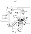
- Fig. 1 is a diagrammatic view of engine controller of an embodiment of the present invention.
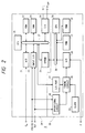
- Fig. 2 is a block diagram of a control unit 9 in Fig. 1.
- Figs. 3A and 3B are a characteristic views showing output of a conventional vibration sensor.
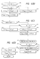
- Fig. 4A a flow-chart which shows calculation of an ignition timing of the present invention.
- Fig. 4B is flow-chart which shows calculation of a advance angle quantity according to the revolution number of the engine in Fig. 4A.
- Fig. 4C is a flow-chart which shows calculation of retard angle quantity in Fig. 4A.
- Fig. 4D is a flow-chart which shows abnormality judgement of the vibration sensor 151.
- Fig. 5 is a ignition timing map in the present invention.
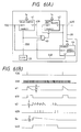
- Fig. 6A is a block diagram of a timing circuit 28 in Fig. 1.
- Fig. 6B is a wave form diagram in Fig. 6A.
- Fig. 7 is a flow-chart which shows an operation of knocking judgement.
- Figs. 8A and 8C show the output signals of the vibration sensor 151 in Figure 1.
- Figs. 8B and 8D show results of frequency analysis of the output signals from the vibration sensor 151.
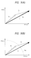
- Figs. 9A and 9B show relations between knocking judgement indexes and threshold values in the present invention.
- the present invention determines a knocking judgement index from at least two resonance frequency components contained in the output of the vibration sensor and judges the occurrence of knocking from the knocking judgement index. Since the occurrence of knocking can be judged from a combination of at least two resonance frequency components of the vibration sensor, vibration due to the occurrence of knocking and background vibration can be separated and discriminated from each other even during a high load, high speed operation where the background vibration is great, and whether or not knocking occurs can be judged.
- the present invention samples the digital value of the output of the vibration sensor ranging from a first crank angle to a second crank angle at predetermined time intervals, stores the result in the memory, analyzes the frequency components on the basis of the memory content and judges the occurrence of knocking by the frequency components. Accordingly, an arbitrary frequency component contained in the output of the vibration sensor can be obtained and the occurrence of knocking can be judged by use of the frequency component in which vibration occurs most remarkably in accordance with the operating state of the engine. Therefore, the occurrence of weak knocking can be judged throughout all the operating conditions of the engine.
- the present invention detects substantially uniformly the engine vibration within the range of from 5 KHz to 20 KHz, and judges the occurrence of knocking on the basis of this detection. Since the occurrence of knocking can be judged in frequency range where background vibration is small such as at the time of the high load high speed operation, whether or not knocking occurs can be judged even at the time of the high load high speed operation.
- the present invention converts the output of the vibration sensor to the digital signal, separates and discriminates, using this digital signal, between other background vibrations and vibration based on knocking by digital processing so as to judge the existence of occurrence of knocking and controls the ignition timing by this judgement. Since separation and discrimination by digital processing can thus be made, the occurrence of knocking can be judged reliably even at the time of the high load high speed operation. Moreover, since the control of advance or retard angle of the ignition timing can thus be made, the engine output as well as fuel efficiency can be improved.
- the first microcomputer judges the occurrence of knocking on the basis of the digital value of the vibration sensor in accordance with the program of the first memory means, and the second microcomputer calculates the ignition timing on the basis of the occurrence of knocking in accordance with the program of the third memory means. Therefore, the first microcomputer conducts complicated processing in accordance with the program and moreover, on the real time basis, and the information contained in the vibration sensor can be utilized effectively. In this manner, the ignition timing control can be made so as to optimize the engine output and fuel efficiency.
- the engine vibration contains a large number of vibration components. They are, for example, the vibration components due to friction of the piston, rotation of the crank shaft, operation of the valve, and so forth. Furthermore, these vibration components change in accordance with the type or condition of the engine.
- vibration inherent to knocking occurs in the engine
- the judgement of the occurrence of knocking is made by separating the vibration inherent to knocking from the overall vibrations of the engine detected by the vibration sensor.
- Figs. 8A and 8B show the output of the vibration sensor when knocking does not occur and the results of analysis of frequency components of the vibration sensor, respectively.
- Figs. 8C and 8D show the output of the vibration sensor when knocking occurs and the results of analysis of the frequency components of the output of the vibration sensor, respectively.
- each resonance frequency component becomes greater than when knocking does not occur.
- the vibration sensor detects a combined vibration of the vibration due to the occurrence of knocking and the vibration containing the background vibration. Accordingly, when knocking does not occur, knocking judgement index I obtained from the vibration sensor outputs becomes I b obtained from only the background vibration, and when the knocking occurs it becomes a combined index of I k obtained from the vibration due to the occurrence of knocking and index I b obtained from the background vibration.
- ⁇ 10, ⁇ 20, ⁇ 01, ⁇ 30 and 11 designate functions depending on number of revolution of the engine and P designates a vibration power spectrum corresponding to each resonance frequency component f10, f20, f01, f30 or f11.
- the knocking judgement index I b represented by the resonance frequency component of the background vibration and the index I k represented by the resonance frequency component of the vibration due to the occurrence of knocking have mutually different directions. This is because the characteristics of the frequency component of each vibration are different and their tone color indices are different as apparent from a human acoustic sense test.
- the second a special tone color, for example a cyclic sound such as "kari kari" is heard.
- the knocking judgement index I due to the f01, f10 components contained in the vibration from the vibration sensor enters into the area under a threshold I01 in Fig. 9A, and in the case shown Fig. 9B the index I enters outside of a threshold I02 so as to judge the occurrence of the knocking.
- the structure of the frequency component being specific to the occurrence of knocking can be taken into consideration in connection with the background vibration so that the occurrence of knocking can be judged even when the background vibration becomes great.
- a hot-wire air flow meter 2 disposed in the duct 3 detects the suction air quantity and this detection signal is inputted to a control unit 9.
- a fuel is injected from a fuel tank, not shown, through an injector 16, is mixed with the intake air inside the suction path and is supplied into the cylinder of the engine 7.
- the air-fuel mixture is compressed in the engine 7, ignited by a spark plug 15 and discharged from an exhaust pipe 8 after explosion.
- An exhaust sensor 11 is disposed in the exhaust pipe 8 and its detection signal is inputted to the control unit 9.
- the high voltage that is generated by the spark coil 13 is distributed to each cylinder by a distributor 14 and is supplied to the spark plug 15.
- a crank angle sensor 12 detects the rotating condition of the engine, and outputs a signal R ef which shows an absolute angle position in each revolution of the engine and signal P os which shows a shifted angle position which is shifted a predetermined angle from the angle R ef .
- the detection signal is inputted to the control unit 9.
- a vibration sensor 151 for detecting vibration is fitted to the engine 7 and its detection signal is inputted to the control unit 9.
- the control unit 9 calculates the fuel supply quantity, the ignition timing etc., on the basis of the signal from each sensor and outputs a control signal to each actuator such as the spark coil.
- Fig. 2 shows the control 9.
- the control unit 9 is divided into a control block 34 consisting of CPU 20, A/D converter 21, ROM 22, input I/O 23, RAM 24, dual port RAM (DPRAM) 25, bus 37 and output I/O 26, and a knocking detection block 35 consisting of CPU 29, port 27, timing circuit 28, A/D convertor 30, ROM 31, RAM 32, bus 36 and clock 33. Data exchange between CPUs 20 and 29 is made through the DPRAM 25.
- the suction air quantity Q a detected by the hot-wire flow meter 2 is converted to a digital value by the A/D converter 21 and is inputted to CPU 20.
- the signal R ef and the signal P os detected by the crank angle sensor 12 are inputted to CPU 20 through I/O 23.
- CPU 20 perform processing in accordance with the program stored in ROM 22 and the result of the processing is transmitted as the fuel injection time T i which means a injection quantity and the ignition timing signal ⁇ ign from the output I/O 26 to each actuator.
- the data necessary for the processing are held by RAM 24.
- a timing circuit 28 divides the frequency of the period signal which is generated by a clock 33, in accordance with the content inputted by CPU 20 to the port 27, and generates a sampling signal.
- the A/D convector 30 converts the output signal of the vibration sensor 151 to a digital value.
- a conventional vibration sensor resonates near at 13 KHz as shown in Fig. 3A but this invention uses a vibration sensor which resonates at 17 KHz or higher as shown in Fig. 3B in order to obtain the resonance frequency components of at least from 17 to 20 KHz.
- CPU 27 lets RAM 32 stores the digital value sampled in accordance with the program stored in ROM 31, analyzes the frequency on the basis of the stored data and judges the occurrence of knocking. The result of this judgement is transmitted to CPU 20 through DPRAM 25.
- the calculation operation of the ignition timing executed in every ignition cycles by CPU 20 will be explained with reference to the flowchart shown in Fig. 4A.
- the operation of this flowchart is initiated at a predetermined time interval, e.g. every 20 msec.
- the number of revolutions N of the engine and the suction air quantity Q are read from predetermined registers inside RAM 24 at step 201.
- the suction air quantity per unit number of revolutions, that is, Q/N is calculated.
- a fuel injection time T i is determined from this Q/N and a basic ignition timing ⁇ base is determined from a basic ignition timing map stored in ROM 22 for fuel supply such as shown in Fig. 5.
- step 203 whether or not knocking occurs is judged in accordance with the content of a later appearing knock flag in Fig. 7. If knocking occurs at this time, subtraction is made between a ignition timing ⁇ adv and a predetermined retard angle quantity ⁇ ret at step 213. Incidentally, this subtraction retards the ignition timing.
- a counter A is initialized at step 214 and then flow proceeds to step 208, in which the counter A is in RAM 24 and is set a recovering pace by comparing the ignition timing retarded when the knocking occurs with a predetermined number of times, for example 50 in Fig. 4A step 205.
- step 213 in order to prevent an occurrence of a violent knocking at high speed of the engine, the retard angle quantity is varied according to the revolution of the engine as shown in a flowchart of Fig. 4C.
- the retard angle quantity is varied according to the revolution of the engine as shown in a flowchart of Fig. 4C.
- whether or not the number of revolutions N of the engine is greater than a predetermined number of revolutions N2 is judged at step 231.
- retard angle quantity ⁇ ret1 is set to be the retard angle quantity ⁇ ret1 is set to be the retard angle quantity ⁇ ret : If N is greater than the predetermined number of revolutions N2, ⁇ ret2 which is greater than ⁇ ret1 is set to be ⁇ ret at step 233 so as to set a proper retard angle quantity.
- Fig. 4A if knocking occurs at step 203, the count data A is counted up by one at step 204. This count data A is set in order to judge whether or not the ignition timing ⁇ adv retarded by the occurrence of the knocking is reached to a time when the advance angle quantity ⁇ adv is recovered. Next, whether or not the count data A is equal to a predetermined value 50 is judged at step 205. Since this flowchart in Fig. 4A is actuated every 20 msec, one second has passed after the initialization of the count data A when the count data A becomes equal to 50, and recovery is made every one second If the counter data A is not equal to 50 at step 205, the flowchart proceeds to step 206. The predetermined advance angle quantity ⁇ adv is added to the retard angle value ⁇ adv at this step 206, and this addition recovers the ignition timing.
- the advance angle quantity ⁇ adv may be made variable on the basis of the number of revolutions in order to suppress the occurrence of the violent knocking caused by a radical change in the advance angle.
- advance angle quantity ⁇ adv2 which is smaller than ⁇ adv2 which is smaller than ⁇ adv1 is used as the advance angle quantity ⁇ adv at step 223 so as to change the advance angle gradually.
- the ignition timing ⁇ ign is then calculated on the basis of the basic ignition timing ⁇ base and the advance angle value ⁇ adv stated as above at step 208.
- the maximum advance angle value ⁇ res is determined in accordance with the suction air quantity Q/N per number of revolutions N of the engine and per unit number of revolutions at step 209. This maximum advance angle value ⁇ res is read out from the maximum advance angle value map stored in ROM 31. Then, whether or not the ignition timing ⁇ ign exceeds the maximum advance angle value ⁇ res is judged at step 210. If it does not, the flowchart proceeds to step 211. If it does, the maximum advance angle value ⁇ res is used as the ignition timing ⁇ ign because the advance angle is too great, at step 211.
- Fig. 4D shows that before executing step 202, abnormality judgement of the vibration sensor is performed on the basis of the output of the vibration sensor after the number of revolutions N and the suction air quantity Q are inputted so as to improve the reliability of the vibration sensor.
- step 20 After the number of revolutions N and the suction air quantity Q are inputted at step 20, whether or not the number of revolutions N of the engine is greater than a predetermined number of revolutions N3 is judged at step 231. If the former is smaller than the latter, the flow proceeds to step 202 because the output of the vibration sensor is not so great that abnormality detection can be made.
- step 232 If the number of revolutions of the engine is found greater than the predetermined number of revolution N3 at step 231, whether or not the vibration sensor output is greater than a predetermined level K is judged at step 232. If it is, the vibration sensor is judged as being normal and the flow proceeds to step 202. If the output of the vibration sensor is smaller than a predetermined level, the vibration sensor is judged as being abnormal, and the ignition timing for the case of abnormality of the vibration sensor is determined at step 234. At this step 234, the ignition timing ⁇ irr for abnormality in accordance with the suction air quantity per number of revolutions N and per unit revolution is searched from the map stored in ROM 22.
- the ignition timing ⁇ irr for abnormality thus searched is a value which is sufficiently retarded from the value stored in the map of the basic ignition timing, and is a value which does not generate knocking.
- ⁇ irr is used as the basic ignition timing ⁇ base and the flow is completed without calculating the ignition timing otherwise required by the detection of knocking.
- a delay time t d the number of sampling points n s and a frequency division ratio t s are outputted to the port 27 in accordance with the engine condition.
- the main comparison resonance frequency f is set to DPRAM 25 in accordance with the engine condition at step 213 and the flowchart in Fig. 4A is then completed.
- the sampling period of the digital values of the output of the vibration sensor is determined by the frequency division ratio t s and the number of sampling points is determined by the number of sampling points n s .
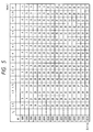
- Table 2 illustrates those frequency components which is set in DPRAM 25 and is selected when the number of sampling points is 16 and the sampling period is 25 »sec, 26.4 »sec and 25.9 »sec, respectively.
- Table 2 is referred in order to get a frequency corresponding to the main resonance frequency in Table 1.
- resolution of the frequency analysis is determined by the sampling period and the number of sampling points.
- the values t d and n s that are set at step 212 are determined and set so that the resonance frequency components necessary for the judgement of the existence of occurrence of knocking in accordance with the operating condition of the engine can be obtained.
- Fig. 6 shows the timing circuit 28 and its operation diagram.
- the timing circuit 28 consists of a delay counter 41, a sample rate count 42, a sample counter 44 and an AND gate 43 equipped with an inverter at its input terminal.
- the TDC signal is inputted to the set terminal of the delay counter 41 and to the set terminal of the sample counter 44.
- the output of the clock 33 is inputted to the enable terminal of the delay counter 41 and to the inverter carrying terminal of the AND gate 43.
- the output of the AND gate 43 is inputted to the enable terminal of the sample rate counter 42.
- the zero output of the sample rate counter 42 is inputted to the enable terminal of the sample counter 44. It is also inputted to the set terminal of the sample rate counter 42 itself and is further outputted as the sampling signal.
- the zero output of the sampling counter 44 is inputted to the AND gate 43.
- the TDC signal is the one that is outputted when the angle of the crank shaft reaches an angle corresponding to the top dead center. It is produced by hardwares or softwares inside CPU 20 from the R ef signal and P os signal outputted from the crank angle sensor.
- the down-count value of the delay counter reaches zero, the zero output of the delay counter becomes zero and 1 is inputted to the AND gate 43.
- the sample counter 44 since the sample counter 44 has already received the TDC signal under this state and the zero output has become 1, the output signal of the clock 33 is, as it is, inputted to the enable terminal of the sample rate counter 42.
- the sample rate counter 42 counts down whenever the clock signal is generated and outputs the sampling signal whenever the count value reaches zero. It inputs the signal to the set terminal of its own and uses again t d as the count value. The zero output is inputted to the enable terminal of the sampling counter 44. When down-count is made and the counter value of the sample counter 44 becomes zero, the zero output becomes zero and the clock signal cannot pass through the AND gate so that the sampling signal is not outputted and more.
- this flowchart is activated as an interrupt signal is outputted to CPU 29 when a predetermined number of digital values of the output of the vibration sensor 15 are held in memory inside RAM 32, that is, when the output of the zero terminal of the sample counter 44 falls from 1 to zero.
- step 300 of Fig. 7 the output data from the vibration sensor 151 is analyzed it's frequency using FFT (Fast Fourier Transformation) method.
- FFT Fast Fourier Transformation
- the analyzed data is memorized as sampling data stored in RAM 32.
- FFT method is used. If needed, WFT (Walch to Fourier Transformation) method may the used.
- step 301 the main resonance frequency f is selected which is used when the knocking judgement index I is calculated with the formula (1) .
- This selection method is performed by selecting the greatest n (n ⁇ 5) of the five power spectra P(f01), P(f20) , P(f01) , P(f30) and P(f11) respectively corresponding to the five resonance frequencies f01, f20, f01, f30 and f11.
- step 302 the knocking judgement index I is calculated from the selected power spectra in the basis of the formula (1).
- the knocking judgement index I is calculated shown as Fig. 9A and 9B.
- A is a contributing factor.
- the value P ⁇ is revised only when there is not the occurrence of the knocking. Initial value of P is read out from ROM 31.
- step 303 the revolutional number N and the air quantity Q are read out from RAM 32.
- step 304 the threshold value I01 or I02 is selected by referring a table equipped in the ROM 31 according to above stated N and Q. If the main resonance frequency is greater than the threshold value I01 or I02, the knocking is judged as occurring at step 305 and the knocking flag is set to "1". If the main resonance frequency is smaller than the threshold value I01 or I02, the knocking is judged as not occurring and the knocking flag is set to "0", and is written in DPRAM 25.
- the flowchart shown in Fig. 7 is executed before starting of the flowchart shown in Fig. 4A. That is to say, the flowchart shown in Fig. 4A is a program for determining the ignition timing before starting of a explosion stroke concerning a certain cylinder of the engine, and the flowchart in Fig. 4A is usually executed in a compression or suction stroke of the engine, but in the flowchart in Fig. 7 it is executed just after the explosion stroke.
- the invention can judge the existence of occurrence of knocking from the tone color index, the judgement of the existence of occurrence of knocking can be made even at the time of the high load high speed operation where the background vibration is great.
- the invention can use an arbitrary frequency component contained in the vibration sensor, the judgement of the existence of occurrence of knocking can be made by use of a suitable resonance frequency component in accordance with the operating condition of the engine. Therefore, whether or not weak knocking occurs can be judged throughout all the operating conditions of the engine.
- the invention can judge the existence of occurrence of knocking by use of the resonance frequency component in which the background vibration becomes small at the time of the high load high speed operation, whether or not knocking occurs can be judged even at the time of the high load high speed operation.
- the invention can judge the existence of occurrence of knocking at the time of the high load high speed operation, the engine output and fuel efficiency can be improved.
- the invention can utilize effectively the information contained in the output of the vibration sensor, the optimum control of the engine output and fuel efficiency can be made.
Landscapes
- Engineering & Computer Science (AREA)
- Chemical & Material Sciences (AREA)
- Combustion & Propulsion (AREA)
- Mechanical Engineering (AREA)
- General Engineering & Computer Science (AREA)
- Physics & Mathematics (AREA)
- General Physics & Mathematics (AREA)
- Signal Processing (AREA)
- Combined Controls Of Internal Combustion Engines (AREA)
- Electrical Control Of Ignition Timing (AREA)
- Measurement Of Mechanical Vibrations Or Ultrasonic Waves (AREA)
Claims (17)
- Motorregler mit einer Vorrichtung zur Bestimmung des Auftretens eines Klopfzustands des Motors, umfassend:
einen Sensor (151) zum Abtasten einer in einem Zylinder des Motors auftretenden Innendruckvibration;
eine Klopferfassungseinrichtung (35) zur Bestimmung des Auftretens des Klopfzustands durch Gewinnung mindestens zweier Frequenzkomponenten, die in einer Ausgabe des Sensors (151) enthalten sind, und eine Regeleinrichtung (9) zur Regelung einer Zündzeitpunktverstellung des Motors basierend auf einer Ausgabe der Klopferfassungseinrichtung und einer Grundzündpunkteinstellung, dadurch gekennzeichnet, daß die Klopferfassungseinrichtung (35) eine Einrichtung zur Gewinnung eines Klopfbestimmungsindexes basierend auf den beiden Frequenzkomponenten aufweist, sowie eine Einrichtung zum Vergleich des Klopfbestimmungsindexes mit einem Schwellenwert, um die Ausgabe an die Regeleinrichtung vorzusehen. - Motorregler mit einer Vorrichtung zur Bestimmung des Auftretens eines Klopfzustands des Motors nach Anspruch 1, wobei die Klopferfassungseinrichtung (35) den Klopfbestimmungsindex aus mindestens zwei Vibrationsleistungsfaktoren, die den Frequenzen entsprechen, erhält.
- Motorregler mit einer Vorrichtung zur Bestimmung des Auftretens eines Klopfzustands des Motors nach Anspruch 1 oder 2, wobei der Sensor (151) ein Abtastintervall zum Abtasten der Vibration verändert.
- Motorregler mit einer Vorrichtung zur Bestimmung des Auftretens eines Klopfzustands des Motors nach einem der vorstehenden Ansprüche, wobei der Sensor (151) eine konstante Empfindlichkeit in einem Frequenzbereich von 5 bis 20 Khz aufweist.
- Motorregler mit einer Vorrichtung zur Bestimmung des Auftretens eines Klopfzustands des Motors nach einem der vorstehenden Ansprüche, wobei die Regeleinrichtung (5) die Zündverstellung um einen vorbestimmten Winkel verzögert, wenn die Klopferfassungseinrichtung das Auftretens des Klopfzustands feststellt.
- Motorregler mit einer Vorrichtung zur Bestimmung des Auftretens eines Klopfzustands des Motors nach Anspruch 1, wobei die Klopferfassungseinrichtung (35) einen ersten Computer zum Speichern eines Programms zur Bestimmung des Auftretens eines Klopfzustands aufweist und dieses Programm ausführt, und wobei die Regeleinrichtung einen zweiten Computer (34) zur Berechnung der Zündzeitpunktverstellung des Motors basierend auf der Ausgabe der Klopferfassungseinrichtung und der Grundzündzeitpunkteinstellung aufweist.
- Motorregler mit einer Vorrichtung zur Bestimmung des Auftretens eines Klopfzustands des Motors nach einem der vorstehenden Ansprüche, wobei der Sensor (151) ein Signal abgibt, wenn die Vibration in vorbestimmter Häufigkeit abgetastet worden ist, wobei die Klopferfassungseinrichtung (35) das Auftreten eines Klopfzustands basierend auf dem Signal des Sensors (151) bestimmt, und wobei die Regeleinrichtung (9) die Zündverstellung des Motors basierend auf der Ausgabe der Klopferfassungseinrichtung in einem vorbestimmten Zyklus regelt.
- Motorregler nach Anspruch 1, dadurch gekennzeichnet, daß die Klopferfassungseinrichtung (35) eine Einrichtung zur Umsetzung der durch den Sensor abgetasteten Vibration in digitale Signale umfaßt, und wobei auf der Basis einer digitalen Frequenzanalyse der digitalen Signale mindestens zwei Frequenzkomponenten gewonnen werden.
- Motorregler mit einer Vorrichtung zur Bestimmung des Auftretens eines Klopfzustands des Motors nach Anspruch 8, wobei der Sensor (151) ein Abtastintervall zum Abtasten der Vibration verändert.
- Motorregler mit einer Vorrichtung zur Bestimmung des Auftretens eines Klopfzustands des Motors nach Anspruch 8 oder 9, wobei die Klopferfassungseinrichtung (35) die abgetastete Vibration durch Verwendung eines schnellen Fourier-Transformationsverfahrens oder eines Walch-Fourier-Transformationsverfahrens in digitale Signale umsetzt.
- Motorregler mit einer Vorrichtung zur Bestimmung des Auftretens eines Klopfzustands des Motors nach einem der Ansprüche 8, 9 oder 10, wobei der Sensor eine konstante Empfindlichkeit in einem Frequenzbereich von 5 bis 20 Khz aufweist.
- Motorregler mit einer Vorrichtung zur Bestimmung des Auftretens eines Klopfzustands des Motors nach einem der Ansprüche 8 oder 11, wobei die Regeleinrichtung (5) die Zündzeitpunktverstellung um einen vorbestimmten Winkel verzögert, wenn die Klopferfassungseinrichtung das Auftreten des Klopfzustands feststellt.
- Motorregler mit einer Vorrichtung zur Bestimmung des Auftretens eines Klopfzustands des Motors nach Anspruch 8, wobei die Klopferfassungseinrichtung (35) einen ersten Computer zum Speichern eines Programms zur Bestimmung des Auftretens eines Klopfzustands aufweist und dieses Programm ausführt, und wobei die Regeleinrichtung einen zweiten Computer (34) zur Berechnung der Zündzeitpunktverstellung des Motors basierend auf der Ausgabe der Klopferfassungseinrichtung und der Grundzündzeitpunkteinstellung aufweist.
- Motorregler mit einer Vorrichtung zur Bestimmung des Auftretens eines Klopfzustands des Motors nach Anspruch 8, wobei der Sensor (151) ein Signal abgibt, wenn die Vibration in vorbestimmter Häufigkeit abgetastet worden ist, wobei die Klopferfassungseinrichtung (35) das Auftreten eines Klopfzustands basierend auf dem Signal des Sensors (151) bestimmt, und wobei die Regeleinrichtung (9) die Zündverstellung des Motors basierend auf der Ausgabe der Klopferfassungseinrichtung in einem vorbestimmten Zyklus regelt.
- Motorregler mit einer Vorrichtung zur Bestimmung des Auftretens eines Klopfzustands des Motors nach Anspruch 8, wobei die Klopferfassungseinrichtung einen Analog-Digital-Umsetzer (30) zum Umsetzen der durch den Sensor abgetasteten Vibration in digitale Signale umfaßt, sowie eine CPU (29) zur Gewinnung von zwei Frequenzkomponenten aus den digitalen Signalen durch Fourier-Transformation, um basierend auf den beiden Frequenzkomponenten den Klopfbestimmungsindex zu erzielen, und wobei der Klopfbestimmungsindex mit dem Schwellenwert verglichen wird.
- Motorregler mit einer Vorrichtung zur Bestimmung des Auftretens eines Klopfzustands des Motors nach Anspruch 15, wobei die CPU (29) den Klopfbestimmungsindex auf der Basis von Verhältnissen der beiden Frequenzkomponenten zu einem Durchschnittswert erzielt, der die beiden im vorherigen Klopfen erfaßten Frequenzkomponenten aufweist.
- Motorregler mit einer Vorrichtung zur Bestimmung des Auftretens eines Klopfzustands des Motors nach Anspruch 16, wobei die CPU (29) den Klopfbestimmungsindex auf der Basis der Verhältnisse erzielt, welche einen vorbestimmten Wert überschreiten.
Applications Claiming Priority (2)
| Application Number | Priority Date | Filing Date | Title |
|---|---|---|---|
| JP92864/89 | 1989-04-14 | ||
| JP9286489 | 1989-04-14 |
Publications (3)
| Publication Number | Publication Date |
|---|---|
| EP0392804A2 EP0392804A2 (de) | 1990-10-17 |
| EP0392804A3 EP0392804A3 (de) | 1991-07-31 |
| EP0392804B1 true EP0392804B1 (de) | 1995-02-22 |
Family
ID=14066297
Family Applications (1)
| Application Number | Title | Priority Date | Filing Date |
|---|---|---|---|
| EP90303853A Expired - Lifetime EP0392804B1 (de) | 1989-04-14 | 1990-04-10 | Motorüberwacher, ausgerüstet mit Klopfdetektor |
Country Status (4)
| Country | Link |
|---|---|
| US (1) | US4991553A (de) |
| EP (1) | EP0392804B1 (de) |
| KR (1) | KR0147278B1 (de) |
| DE (1) | DE69017063T2 (de) |
Families Citing this family (31)
| Publication number | Priority date | Publication date | Assignee | Title |
|---|---|---|---|---|
| US5038735A (en) * | 1989-10-30 | 1991-08-13 | Mitsubishi Denki Kabushiki Kaisha | Knock suppression apparatus and method for a multi-cylinder internal combustion engine |
| JP2843871B2 (ja) * | 1990-05-14 | 1999-01-06 | 本田技研工業株式会社 | 内燃エンジンの燃焼異常検出装置 |
| US5146893A (en) * | 1990-05-18 | 1992-09-15 | Mitsubishi Denki K.K. | Apparatus for and a method of detecting combustion in an internal combustion engine |
| DE59008539D1 (de) * | 1990-05-28 | 1995-03-30 | Siemens Ag | Verfahren zur zylinderselektiven Klopfregelung von Brennkraftmaschinen. |
| JP2587543B2 (ja) * | 1991-03-07 | 1997-03-05 | 株式会社日立製作所 | ノッキング検出装置 |
| US5373448A (en) * | 1991-04-24 | 1994-12-13 | Hitachi, Ltd. | Knock detection device for an internal combustion engine |
| JP3117495B2 (ja) * | 1991-07-19 | 2000-12-11 | 株式会社日立製作所 | ノッキング検出装置 |
| US5215059A (en) * | 1992-04-03 | 1993-06-01 | Hitachi America, Ltd., Research And Development Division | Method and system for reducing engine knock in an internal combustion engine |
| US5400644A (en) * | 1992-09-29 | 1995-03-28 | Motorola, Inc. | Knock detection system |
| JP3668497B2 (ja) * | 1992-09-30 | 2005-07-06 | 株式会社日立製作所 | 内燃機関のノッキング検出方法及び点火時期制御方法 |
| US5394330A (en) * | 1992-11-12 | 1995-02-28 | Texas Instruments Incorporated | System and method for monitoring an operating state of an engine |
| US6456927B1 (en) | 1993-03-22 | 2002-09-24 | Motorola, Inc. | Spectral knock detection method and system therefor |
| US5537855A (en) * | 1994-06-30 | 1996-07-23 | Motorola, Inc. | Knock detection method and apparatus with dual integration windows |
| US5483936A (en) * | 1994-07-05 | 1996-01-16 | Kerstein; Scott M. | Spark knock detection system for an internal combustion engine |
| US5675505A (en) * | 1995-07-10 | 1997-10-07 | Chrysler Corporation | Sine on random data analysis method for simulating engine vibration |
| EP1007842B1 (de) * | 1997-08-22 | 2004-12-15 | Siemens Aktiengesellschaft | Verfahren zur klopfregelung einer brennkraftmaschine |
| SE520435C2 (sv) * | 2001-03-30 | 2003-07-08 | Scania Cv Ab | Sätt och anordning för att bestämma cylindertryck vid en förbränningsmotor |
| DE10201073A1 (de) | 2002-01-14 | 2003-07-31 | Siemens Ag | Verfahren zur Verarbeitung eines Sensorsignals eines Klopf-Sensors für eine Brennkraftmaschine |
| US20040260454A1 (en) * | 2003-06-11 | 2004-12-23 | Basir Otman A. | Vibro-acoustic engine diagnostic system |
| JP4375728B2 (ja) * | 2004-04-15 | 2009-12-02 | 株式会社デンソー | 内燃機関の制御装置 |
| JP4397804B2 (ja) * | 2004-12-27 | 2010-01-13 | 本田技研工業株式会社 | ノッキング検出装置 |
| JP2006226967A (ja) * | 2005-02-21 | 2006-08-31 | Toyota Motor Corp | 内燃機関のノッキング判定装置 |
| JP4549920B2 (ja) * | 2005-04-27 | 2010-09-22 | トヨタ自動車株式会社 | 内燃機関のノッキング判定装置 |
| ITBO20050789A1 (it) * | 2005-12-23 | 2007-06-24 | Ferrari Spa | Metodo per il controllo dell'anticipo di accensione in un motore a combustione interna. |
| JP2008095602A (ja) * | 2006-10-12 | 2008-04-24 | Denso Corp | 内燃機関のノック判定装置 |
| JP4475675B2 (ja) | 2007-05-11 | 2010-06-09 | 三菱電機株式会社 | 内燃機関のノック検出装置 |
| FR2916480B1 (fr) * | 2007-05-25 | 2009-07-17 | Siemens Vdo Automotive Sas | Procede de detection de cliquetis perfectionne. |
| FR2949511B1 (fr) * | 2009-08-26 | 2012-03-09 | Inst Francais Du Petrole | Methode d'estimation de l'intensite du cliquetis d'un moteur a combustion interne |
| JP6088397B2 (ja) * | 2013-10-15 | 2017-03-01 | 日本特殊陶業株式会社 | 点火時期制御装置および点火時期制御システム |
| JP6288699B2 (ja) * | 2014-01-10 | 2018-03-07 | 三菱重工業株式会社 | 内燃機関のノッキング判定装置及びノッキング制御装置 |
| US11067022B1 (en) | 2016-02-16 | 2021-07-20 | Hitachi Automotive Systems, Ltd. | Knocking detection apparatus and internal combustion engine control apparatus |
Family Cites Families (8)
| Publication number | Priority date | Publication date | Assignee | Title |
|---|---|---|---|---|
| US4345558A (en) * | 1979-04-28 | 1982-08-24 | Nippon Soken, Inc. | Knock detecting apparatus for an internal combustion engine |
| JPS55144520A (en) * | 1979-04-28 | 1980-11-11 | Nippon Soken Inc | Knocking detector for internal combustion engine |
| JPS55162037A (en) * | 1979-06-04 | 1980-12-17 | Nippon Soken Inc | Knocking detector for internal combustion engine |
| JPS55177623U (de) * | 1979-06-06 | 1980-12-19 | ||
| JPS5637535A (en) * | 1979-09-05 | 1981-04-11 | Nippon Soken Inc | Knocking detector |
| JPS5742821A (en) * | 1980-08-27 | 1982-03-10 | Nissan Motor Co Ltd | Knocking vibration detector |
| JPS5845520A (ja) * | 1981-09-11 | 1983-03-16 | Matsushita Electric Ind Co Ltd | ノツキング検出装置 |
| JPH0650103B2 (ja) * | 1982-01-18 | 1994-06-29 | 株式会社日立製作所 | ノツク制御装置 |
-
1990
- 1990-04-10 DE DE69017063T patent/DE69017063T2/de not_active Expired - Lifetime
- 1990-04-10 EP EP90303853A patent/EP0392804B1/de not_active Expired - Lifetime
- 1990-04-13 US US07/508,657 patent/US4991553A/en not_active Expired - Lifetime
- 1990-04-14 KR KR1019900005188A patent/KR0147278B1/ko not_active IP Right Cessation
Also Published As
| Publication number | Publication date |
|---|---|
| KR900016609A (ko) | 1990-11-14 |
| US4991553A (en) | 1991-02-12 |
| DE69017063D1 (de) | 1995-03-30 |
| DE69017063T2 (de) | 1995-09-21 |
| EP0392804A2 (de) | 1990-10-17 |
| EP0392804A3 (de) | 1991-07-31 |
| KR0147278B1 (ko) | 1998-08-17 |
Similar Documents
| Publication | Publication Date | Title |
|---|---|---|
| EP0392804B1 (de) | Motorüberwacher, ausgerüstet mit Klopfdetektor | |
| KR100364455B1 (ko) | 내연기관의 노킹검출방법 | |
| US5392642A (en) | System for detection of low power in at least one cylinder of a multi-cylinder engine | |
| US7347081B2 (en) | Knock detecting apparatus and method for internal combustion engine | |
| EP0424630A2 (de) | Methode und Gerät, um den Verbrennungszustand in einer Brennkraftmaschine zu Detektieren, und solche Methode und Gerät benutzende Methode und Gerät zur Steuerung einer Verbrennungsmaschine | |
| US5214958A (en) | Misfiring detecting apparatus for an internal combustion device | |
| JP3315724B2 (ja) | 失火検出装置 | |
| US5347846A (en) | Knocking detecting device for internal combustion engine and method therefor | |
| US5638278A (en) | Apparatus for detecting an occurence of misfiring in an engine cylinder | |
| JP3325067B2 (ja) | 内燃機関のノッキング検出装置 | |
| JP2684611B2 (ja) | ノッキング検出装置 | |
| JPH0526721A (ja) | ノツキング検出装置 | |
| US5503007A (en) | Misfire detection method and apparatus therefor | |
| JP3031071B2 (ja) | エンジン制御装置 | |
| JP2730490B2 (ja) | ノッキング検出装置 | |
| JP2675921B2 (ja) | 内燃機関の失火検出装置 | |
| EP0709663A1 (de) | Verfahren und Gerät zur Erfassung von Fehlzündungen | |
| JPH05125991A (ja) | ノツク検出装置 | |
| JP2932917B2 (ja) | 内燃機関の燃焼状態制御装置 | |
| JP2858286B2 (ja) | 内燃機関の気筒判別装置 | |
| JPS6229638Y2 (de) | ||
| JPH04166647A (ja) | ノック検出装置 | |
| JPH0658299B2 (ja) | 失火検出装置 | |
| JPH06200859A (ja) | ノッキング制御方法および装置 | |
| JPH06186115A (ja) | ノッキング制御方法および装置 |
Legal Events
| Date | Code | Title | Description |
|---|---|---|---|
| PUAI | Public reference made under article 153(3) epc to a published international application that has entered the european phase |
Free format text: ORIGINAL CODE: 0009012 |
|
| 17P | Request for examination filed |
Effective date: 19900504 |
|
| AK | Designated contracting states |
Kind code of ref document: A2 Designated state(s): DE FR GB |
|
| PUAL | Search report despatched |
Free format text: ORIGINAL CODE: 0009013 |
|
| RHK1 | Main classification (correction) |
Ipc: F02P 5/04 |
|
| AK | Designated contracting states |
Kind code of ref document: A3 Designated state(s): DE FR GB |
|
| 17Q | First examination report despatched |
Effective date: 19940520 |
|
| GRAA | (expected) grant |
Free format text: ORIGINAL CODE: 0009210 |
|
| AK | Designated contracting states |
Kind code of ref document: B1 Designated state(s): DE FR GB |
|
| REF | Corresponds to: |
Ref document number: 69017063 Country of ref document: DE Date of ref document: 19950330 |
|
| ET | Fr: translation filed | ||
| PLBE | No opposition filed within time limit |
Free format text: ORIGINAL CODE: 0009261 |
|
| STAA | Information on the status of an ep patent application or granted ep patent |
Free format text: STATUS: NO OPPOSITION FILED WITHIN TIME LIMIT |
|
| 26N | No opposition filed | ||
| REG | Reference to a national code |
Ref country code: GB Ref legal event code: IF02 |
|
| PGFP | Annual fee paid to national office [announced via postgrant information from national office to epo] |
Ref country code: DE Payment date: 20090525 Year of fee payment: 20 |
|
| PGFP | Annual fee paid to national office [announced via postgrant information from national office to epo] |
Ref country code: FR Payment date: 20090309 Year of fee payment: 20 |
|
| PGFP | Annual fee paid to national office [announced via postgrant information from national office to epo] |
Ref country code: GB Payment date: 20090402 Year of fee payment: 20 |
|
| REG | Reference to a national code |
Ref country code: GB Ref legal event code: PE20 Expiry date: 20100409 |
|
| PG25 | Lapsed in a contracting state [announced via postgrant information from national office to epo] |
Ref country code: GB Free format text: LAPSE BECAUSE OF EXPIRATION OF PROTECTION Effective date: 20100409 |
|
| PG25 | Lapsed in a contracting state [announced via postgrant information from national office to epo] |
Ref country code: DE Free format text: LAPSE BECAUSE OF EXPIRATION OF PROTECTION Effective date: 20100410 |