EP0389221A1 - Herstellungsverfahren von Elektroden für Elektroentladungsbearbeitung, die wie ein wabenförmiger Stempel aussehen und Herstellungsverfahren von wabenförmigen Stempeln - Google Patents
Herstellungsverfahren von Elektroden für Elektroentladungsbearbeitung, die wie ein wabenförmiger Stempel aussehen und Herstellungsverfahren von wabenförmigen Stempeln Download PDFInfo
- Publication number
- EP0389221A1 EP0389221A1 EP90302930A EP90302930A EP0389221A1 EP 0389221 A1 EP0389221 A1 EP 0389221A1 EP 90302930 A EP90302930 A EP 90302930A EP 90302930 A EP90302930 A EP 90302930A EP 0389221 A1 EP0389221 A1 EP 0389221A1
- Authority
- EP
- European Patent Office
- Prior art keywords
- electrode
- electrical discharge
- discharge machining
- grinding
- grinding wheel
- Prior art date
- Legal status (The legal status is an assumption and is not a legal conclusion. Google has not performed a legal analysis and makes no representation as to the accuracy of the status listed.)
- Granted
Links
- 238000009760 electrical discharge machining Methods 0.000 title claims abstract 22
- 238000004519 manufacturing process Methods 0.000 title claims 6
- 239000007772 electrode material Substances 0.000 claims abstract 24
- 238000005520 cutting process Methods 0.000 claims abstract 17
- 239000011295 pitch Substances 0.000 claims abstract 10
- 238000000034 method Methods 0.000 claims 6
- 239000000463 material Substances 0.000 claims 4
- 230000002093 peripheral effect Effects 0.000 claims 4
- 238000003754 machining Methods 0.000 claims 3
- 230000015572 biosynthetic process Effects 0.000 claims 2
Images



Classifications
-
- B—PERFORMING OPERATIONS; TRANSPORTING
- B28—WORKING CEMENT, CLAY, OR STONE
- B28B—SHAPING CLAY OR OTHER CERAMIC COMPOSITIONS; SHAPING SLAG; SHAPING MIXTURES CONTAINING CEMENTITIOUS MATERIAL, e.g. PLASTER
- B28B3/00—Producing shaped articles from the material by using presses; Presses specially adapted therefor
- B28B3/20—Producing shaped articles from the material by using presses; Presses specially adapted therefor wherein the material is extruded
- B28B3/26—Extrusion dies
- B28B3/269—For multi-channeled structures, e.g. honeycomb structures
-
- B—PERFORMING OPERATIONS; TRANSPORTING
- B23—MACHINE TOOLS; METAL-WORKING NOT OTHERWISE PROVIDED FOR
- B23H—WORKING OF METAL BY THE ACTION OF A HIGH CONCENTRATION OF ELECTRIC CURRENT ON A WORKPIECE USING AN ELECTRODE WHICH TAKES THE PLACE OF A TOOL; SUCH WORKING COMBINED WITH OTHER FORMS OF WORKING OF METAL
- B23H1/00—Electrical discharge machining, i.e. removing metal with a series of rapidly recurring electrical discharges between an electrode and a workpiece in the presence of a fluid dielectric
- B23H1/04—Electrodes specially adapted therefor or their manufacture
-
- B—PERFORMING OPERATIONS; TRANSPORTING
- B23—MACHINE TOOLS; METAL-WORKING NOT OTHERWISE PROVIDED FOR
- B23H—WORKING OF METAL BY THE ACTION OF A HIGH CONCENTRATION OF ELECTRIC CURRENT ON A WORKPIECE USING AN ELECTRODE WHICH TAKES THE PLACE OF A TOOL; SUCH WORKING COMBINED WITH OTHER FORMS OF WORKING OF METAL
- B23H9/00—Machining specially adapted for treating particular metal objects or for obtaining special effects or results on metal objects
-
- B—PERFORMING OPERATIONS; TRANSPORTING
- B23—MACHINE TOOLS; METAL-WORKING NOT OTHERWISE PROVIDED FOR
- B23H—WORKING OF METAL BY THE ACTION OF A HIGH CONCENTRATION OF ELECTRIC CURRENT ON A WORKPIECE USING AN ELECTRODE WHICH TAKES THE PLACE OF A TOOL; SUCH WORKING COMBINED WITH OTHER FORMS OF WORKING OF METAL
- B23H2200/00—Specific machining processes or workpieces
- B23H2200/30—Specific machining processes or workpieces for making honeycomb structures
Definitions
- This invention relates to a method for the production of an electrical discharge machining electrode for forming a honeycomb die and to a method for the production of a honeycomb die. Specifically, it is concerned with a production method of an electrical discharge machining electrode suitable for use in forming an extruding die for forming a honeycomb structure (hereinafter referred to as "honeycomb die"), in which an electrical discharge machining electrode adapted to use for cutting forming grooves in the honeycomb die by electrical discharge machining, the dimensions in width of said forming grooves being controlled so as to become greater continuously or stepwise from its center toward the periphery, is produced with high accuracy and efficiency, and with a method for the production of a honeycomb die by making use of the honeycomb die-forming electrical discharge machining electrode.
- honeycomb die an electrical discharge machining electrode adapted to use for cutting forming grooves in the honeycomb die by electrical discharge machining, the dimensions in width of said forming grooves being controlled so as to become greater continuously or stepwise from its center toward the peripher
- honeycomb structures particularly, ceramic-made honeycomb structures have been widely used in various fields as carriers for catalysts useful for purifying exhaust gases from internal combustion engines and combustion furnaces for various kinds of industries, heat-accumulating members of heat exchangers and the like.
- Extruder-die assemblies have been employed in production of the honeycomb structures. Namely, each of the extruder-die assemblies is equipped with a honeycomb die, in which forming grooves are provided having a configuration corresponding to the profile of a honeycomb structure. A raw material is pressed in and extruded through the forming grooves of the honeycomb die, thereby forming the honeycomb structure.
- the present invention can provide a method for the production of an electrical discharge machining electrode for forming a honeycomb die, said electrode being provided with a plurality of electrode groove portions formed by cutting parallel grooves in an electrode material and with a plurality of projecting electrode portions corresponding to forming grooves of the honeycomb die and formed between their corresponding electrode groove portions, comprising the steps of: cutting said parallel grooves by means of a grinding wheel formed in a reverse tapered shape in which the grinding width is gradually widened toward its peripheral direction; and progressively dressing said grinding wheel during the cutting of said parallel grooves.
- the invention provides a method for the production of the electrical discharge machining electrode, wherein: a plurality of grooves are cut in the electrode material by moving the grinding wheel relative to the electrode material so as to cut a groove in the electrode material, and subsequent to the cutting of the groove, relatively moving the grinding wheel and the electrode material by desired pitches in a direction perpendicular to the grinding direction, and dressing the grinding surface of the grinding wheel at every pitch width relative to the movement of the grinding wheel and the electrode material toward the directions of both ends from the center portion for the purpose of narrowing the grinding width, whereby a plurality of electrode groove portions are formed.
- the invention can provide, in a method for the production of an electrical discharge machining electrode for forming a honeycomb die, said electrode being provided with a plurality of electrode groove portions formed by cutting parallel grooves in an electrode material by means of a grinding wheel and with a plurality of projecting electrode portions corresponding to forming grooves of the honeycomb die and formed between their corresponding electrode groove portions, the improvement wherein: the grinding wheel is formed into a reverse tapered shape in which the grinding width is gradually widened toward its peripheral direction; and a plurality of grooves are cut in the electrode material by moving the grinding wheel relative to the electrode material so as to cut a groove in the electrode material, and subsequent to the cutting of the groove, relatively moving the grinding wheel and the electrode material by desired pitches in a direction perpendicular to the grinding direction, and dressing the grinding surface of the grinding wheel at plural pitch distances relative to the movement of the grinding wheel and the electrode material toward the directions of both ends from the center portion for the purpose of narrowing the grinding width, whereby a plurality of electrode groove portions are formed.
- this invention can provide a method for the production of a honeycomb die provided with forming grooves, which have configurations corresponding to the profile of a honeycomb structure and are to be formed by electrical discharge machining making use of a honeycomb die-forming electrical discharge machining electrode provided with a plurality of projecting electrode portions corresponding to the forming grooves, which comprises; using, as the honeycomb die-forming electrical discharge machining electrode, a honeycomb die-forming electrical discharge machining electrode provided with a plurality of electrode groove portions, which have been formed by cutting a plurality of grooves in an electrode material while moving a grinding wheel formed into a reverse tapered shape, in which the grinding width is gradually widened toward its peripheral direction, relative to the electrode material so as to cut a groove in the electrode material, and subsequent to the cutting of the groove, relatively moving the grinding wheel and the electrode material by desired pitches in a direction perpendicular to the grinding direction, and dressing the grinding surface of the grinding wheel at every pitch width relative to the movement of the grinding wheel and the electrode material toward the directions of both ends
- this invention can provide a method for the production of the honeycomb die, further comprising: cutting forming grooves being in rows in one direction relative to a material to be formed by electrical discharge machining making use of the honeycomb die-forming electrical discharge machining electrode; and cutting forming grooves in a direction crossing perpendicularly to said one direction by electrical discharge machining making use of the honeycomb die-forming electrical discharge machining electrode in a condition that the honeycomb die-forming electrical discharge machining electrode and the material to be formed have been relatively rotated by 90°, thereby cutting forming grooves, whose dimensions in width become greater continuously toward both ends from the center, in the honeycomb die.
- this invention can provide a method for the production of a honeycomb die provided with forming grooves, which have configurations corresponding to the profile of a honeycomb structure to be formed and are to be formed by electrical discharge machining using a honeycomb die-forming electrical discharge machining electrode provided with a plurality of projecting electrode portions corresponding to the forming grooves, which comprises; using, as the honeycomb die-forming electrical discharge machining electrode, a honeycomb die-forming electrical discharge machining electrode provided with a plurality of electrode groove portions, which have been formed by cutting a plurality of grooves in an electrode material while moving a grinding wheel formed into a reverse tapered shape, in which the grinding width is gradually widened toward its peripheral direction, relative to the electrode material so as to cut a groove in the electrode material, and subsequent to the cutting of the groove, relatively moving the grinding wheel and the electrode material by desired pitches in a direction perpendicular to the grinding direction, and dressing the grinding surface of the grinding wheel at plural pitch distances relative to the movement of the grinding wheel and the electrode material toward the directions of
- FIG. 1 illustrates a cross-sectional view of a grinding wheel 1 employed in the production method of the honeycomb die-forming electrical discharge machining electrodes according to this invention.
- the grinding wheel 1 is formed into a reverse tapered shape in which the grinding width in cross section is gradually widened toward its peripheral direction. Therefore, it is possible to control the grinding width W (distance between grinding edges 2′ and 2′) of a grinding surface 2 to a desired distance by dressing the grinding surface 2.
- the production method of the electrodes in this invention which is conducted by making use of the above grinding wheel 1, will hereinafter be described with reference to FIG. 2 through FIG. 4.
- the grinding wheel 1 is relatively moves in a depth direction in the drawing on an electrode material 3 to form a electrode groove portion 4.
- a plurality of parallel electrode groove portions 4 having a predetermined depth are similarly cut while the grinding wheel 1 is moved repeatedly and in parallel with the thus-formed electrode groove portion 4 at a desired pitch P, whereby projecting electrode portions 5 are formed between their corresponding electrode groove portions 4.
- the pitch P between adjacent electrode groove portions 4 and respective thicknesses t0, t1, t2 ... of the projecting electrode portions 5 have been predetermined.
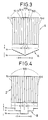
- Desired electrode 6 (FIG. 3) and electrode 7 (FIG. 4) can hence be produced by controlling a grinding width W of the grinding surface 2 in the grinding wheel 1 by dressing, and by parallel-moving the grinding wheel 1 at a pitch P.
- the projecting electrode portion 5(0) situated at the center has a thickness of t0 as is illustrated in FIG. 2.
- the projecting electrodes 5(1) and 5(-1), the projecting electrodes 5(2) and 5(-2), ..., and the projecting electrodes 5(n) and 5(-n) have thicknesses of t1, t2, ..., t n respectively.
- the V-shaped line A drawn in the lower part of FIG. 3 indicates changes of the thicknesses t of the projecting electrode portions 5(0) through 5(n) and 5(-n).
- the electrode 6 is formed in such a manner that supposing the thickness of the projecting electrode portion 5(0) situated at the center is t0, the thicknesses t of the projecting electrode portions 5 become greater continuously toward X and -X directions.
- the electrode 7 depicted in FIG. 4, as is indicated by a step-like line B drawn in the lower part of FIG. 4, is formed in such a manner that supposing the thickness of the projecting electrode portion 5(0) situated at the center is t0, the thicknesses t of the projecting electrode portions 5 become greater stepwise toward X and -X directions.
- the grinding surface 2 of a grinding wheel 1 illustrated in FIG. 1 is dressed to control a grinding width W to W1 so as to cut a groove, thereby forming a electrode groove portion 4(1).
- the grinding width W1 is supposed to be (P - t0).
- the grinding wheel 1 is then moved by a distance P in a -X direction to cut a groove so as to form a electrode groove portion 4(-1).
- a projecting electrode portion 5(0) having a thickness of t0 is formed between the electrode groove portions 4(1) and 4(-1).
- the grinding width W is then changed from W1 to W2 by dressing and at the same time, the grinding wheel 1 is moved by a distance P in the -X direction.
- a groove is then cut to form a electrode groove portion 4(-2), whereby a projecting electrode portion 5(-1) having a thickness of t1 is formed between the electrode groove portion 4(-2) and the electrode groove portions 4(-1).
- supposing (t1 - t0) is ⁇ t
- the grinding width W2 is (W1 - 2x ⁇ t).
- the grinding wheel 1 is then moved by a distance 3P in an X direction.
- a groove is cut to form a electrode groove portion 4(2).
- a projecting electrode portion 5(1) having a thickness of t1 is formed between the electrode groove portions 4(1) and the electrode groove portion 4(2).
- the production method of an electrode 7 illustrated in FIG. 4 is basically the same as that of the electrode 6. Namely, in the production of the electrode 6, the dressing of the grinding wheel 1 has been conducted every other groove cutting, i.e., formation of every two electrode groove portions. In the production of the electrode 7, the dressing may however be conducted at every fourth or sixth groove cutting, i.e., formation of every four or six electrode groove portions.
- the electrode 7, as is indicated by a step-like line B drawn in the lower part of FIG. 4, is formed in such a manner that supposing the thickness of the projecting electrode portion 5(0) situated at the center is t0, the thicknesses t of the projecting electrode portions 5 become greater stepwise toward X and -X directions.
- the thicknesses t of the projecting electrode portions 5 have been changed at three steps. However, such changes are not limited thereto. It is also possible to change the thicknesses t of the projecting electrode portions at every two steps, or four steps or more.
- honeycomb dies according to this invention in which forming grooves for forming honeycomb structures are cut by electrical discharge machining making separate use of the electrodes 6 and 7, is then described with reference to FIGS. 6 and 7.
- a honeycomb die 8 illustrated in FIG. 6 has forming grooves 10 cut by electrical discharge machining making use of the electrode 6.
- the honeycomb die 8 is formed in the following manner. Namely, after forming grooves 10-1 in an X - (-X) direction by way of example are cut by the electrical discharge machining making use of the electrode 6, forming grooves 10-2 in a Y - (-Y) direction are cut in a condition that the electrode 6 has been rotated by 90°.
- the electrode 6 Since the electrode 6 has been formed in such a manner that supposing the thickness of the projecting electrode portion 5(0) situated at the center is t0, the thicknesses t of the projecting electrode portions 5 become greater continuously toward X and -X directions, the groove widths V of the forming grooves 10 in the honeycomb die 8, as is indicated by a V-shaped line A drawn in the lower part of FIG.
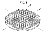
- FIG. 6 A perspective view of the honeycomb die 8 thus produced is shown in FIG. 8.
- a honeycomb die 9 illustrated in FIG. 7 has forming grooves 10 cut by electrical discharge machining making use of the electrode 7.
- the honeycomb die 9 is formed in the following manner. Namely, after forming grooves 10-1 in an X - (-X) direction by way of example are cut by the electrical discharge machining making use of the electrode 7, forming grooves 10-2 in a Y - (-Y) direction are cut in a condition that the electrode 7 has been rotated by 90°.
- the electrode 7 Since the electrode 7 has been formed in such a manner that supposing the thickness of the projecting electrode portion 5(0) situated at the center is t0, the thicknesses t of the projecting electrode portions 5 become greater stepwise toward X and -X directions, the groove widths V of the forming grooves 10 in the honeycomb die 9, as is indicated by a step-like line B drawn in the lower part of FIG.
- honeycomb die wherein the groove widths V of the forming grooves have been changed at every two steps, or four steps or more when using an electrode in which the thicknesses t of the projecting electrode portions 5 in the electrode 7 have been changed at every two steps, or four steps or more.
- the honeycomb die produced has an external dimension ⁇ of 140 mm, a pitch P between forming grooves of 1.4 mm, V0 of 290 ⁇ m and V n of 310 ⁇ m in FIG. 6.
- the honeycomb die produced has an external dimension ⁇ of 140 mm, a pitch P between forming grooves of 1.4 mm, V0 of 290 ⁇ m, v i of 300 ⁇ m and V n of 310 ⁇ m in FIG. 7.
- a method for the production of electrical discharge machining electrodes suitable for use in forming extruding dies for forming honeycomb structures in which an electrical discharge machining electrode for cutting forming grooves in a honeycomb die by electrical discharge machining, the dimensions in width of said forming grooves being controlled so as to become greater continuously or stepwise toward its periphery from the center, is successfully produced with high accuracy and efficiency, and a method for the production of honeycomb dies by making use of the honeycomb die-forming electrical discharge machining electrodes is also provided.
Landscapes
- Engineering & Computer Science (AREA)
- Mechanical Engineering (AREA)
- Manufacturing & Machinery (AREA)
- Chemical & Material Sciences (AREA)
- Ceramic Engineering (AREA)
- Physics & Mathematics (AREA)
- Thermal Sciences (AREA)
- Electrical Discharge Machining, Electrochemical Machining, And Combined Machining (AREA)
- Grinding And Polishing Of Tertiary Curved Surfaces And Surfaces With Complex Shapes (AREA)
- Laminated Bodies (AREA)
Applications Claiming Priority (2)
| Application Number | Priority Date | Filing Date | Title |
|---|---|---|---|
| JP1068806A JP2502144B2 (ja) | 1989-03-20 | 1989-03-20 | ハニカム・ダイス成形用放電加工電極の製造方法及びハニカム・ダイスの製造方法 |
| JP68806/89 | 1989-03-20 |
Publications (2)
| Publication Number | Publication Date |
|---|---|
| EP0389221A1 true EP0389221A1 (de) | 1990-09-26 |
| EP0389221B1 EP0389221B1 (de) | 1993-06-09 |
Family
ID=13384329
Family Applications (1)
| Application Number | Title | Priority Date | Filing Date |
|---|---|---|---|
| EP90302930A Expired - Lifetime EP0389221B1 (de) | 1989-03-20 | 1990-03-19 | Herstellungsverfahren von Elektroden für Elektroentladungsbearbeitung, die wie ein wabenförmiger Stempel aussehen und Herstellungsverfahren von wabenförmigen Stempeln |
Country Status (4)
| Country | Link |
|---|---|
| US (1) | US5008509A (de) |
| EP (1) | EP0389221B1 (de) |
| JP (1) | JP2502144B2 (de) |
| DE (1) | DE69001844T2 (de) |
Cited By (4)
| Publication number | Priority date | Publication date | Assignee | Title |
|---|---|---|---|---|
| EP1287933A3 (de) * | 2001-08-30 | 2005-02-09 | Corning Incorporated | Verfahren zur Herstellung einer Extrusionsdüse mit variierenden Stiftabmessungen |
| EP1537914A4 (de) * | 2002-09-05 | 2006-10-25 | Ngk Insulators Ltd | Wabenstruktur und matritze zur herstellung der wabenstruktur |
| EP1452702A3 (de) * | 2003-02-28 | 2006-12-20 | Ngk Insulators, Ltd. | Wabenstruktur und Matrize zum Extrudieren einer Wabenstruktur |
| EP2085248A1 (de) * | 2008-02-04 | 2009-08-05 | Stefano Rosi | Verfahren zur Herstellung einer Matrize zur Formung einer Fliese |
Families Citing this family (11)
| Publication number | Priority date | Publication date | Assignee | Title |
|---|---|---|---|---|
| US6061212A (en) * | 1995-05-18 | 2000-05-09 | Matsushita Electric Industrial Co., Ltd. | Magnetic head with circular notches and magnetic recording/reproducing apparatus using the same |
| US6448530B1 (en) * | 1998-05-11 | 2002-09-10 | Denso Corporation | Metal mold for molding a honeycomb structure and method of producing the same |
| JP4210446B2 (ja) | 2001-09-19 | 2009-01-21 | 日本碍子株式会社 | ハニカム押出成形用口金及びその製造方法 |
| AT502285B1 (de) * | 2004-10-19 | 2008-12-15 | Gissing Gerhard | Trennschleifring mit doppelter kernspannvorrichtung |
| JP4694821B2 (ja) * | 2004-11-17 | 2011-06-08 | 日本碍子株式会社 | ハニカム構造体成形用口金及びハニカム構造体の製造方法 |
| JP2007302542A (ja) * | 2006-05-15 | 2007-11-22 | Denso Corp | セラミックハニカム成形体の焼成用治具 |
| US20090218322A1 (en) * | 2008-02-28 | 2009-09-03 | David William Folmar | Dies for manufacturing substrates and methods of making |
| US8591287B2 (en) * | 2010-02-26 | 2013-11-26 | Corning Incorporated | Methods of fabricating a honeycomb extrusion die from a die body |
| JP2012125883A (ja) * | 2010-12-15 | 2012-07-05 | Ngk Insulators Ltd | ハニカム構造体成形口金用電極の製造方法 |
| JP7080552B2 (ja) * | 2017-12-28 | 2022-06-06 | 株式会社ディスコ | 切削ブレードのドレッシング方法 |
| CN117260172B (zh) * | 2023-06-05 | 2026-03-31 | 深圳市众为精密科技有限公司 | 一种听筒网模具成型零件精密加工方法 |
Citations (2)
| Publication number | Priority date | Publication date | Assignee | Title |
|---|---|---|---|---|
| DE2600760A1 (de) * | 1976-01-10 | 1977-07-14 | Skf Kugellagerfabriken Gmbh | Elektrode fuer die elektrolytische einarbeitung eines rillenmusters in eine werkstueckflaeche |
| US4350865A (en) * | 1980-11-21 | 1982-09-21 | Ford Motor Company | Method and device for forming a tapered extrusion die |
Family Cites Families (10)
| Publication number | Priority date | Publication date | Assignee | Title |
|---|---|---|---|---|
| US3777595A (en) * | 1971-07-19 | 1973-12-11 | E Hausermann | Method of making a master die for use in an abrasion process |
| US3768344A (en) * | 1971-11-08 | 1973-10-30 | E Feldcamp | Manufacture of extrusion tools |
| FR2199673A5 (de) * | 1972-06-01 | 1974-04-12 | Vial Sarl | |
| JPS5440387A (en) * | 1977-09-07 | 1979-03-29 | Hitachi Ltd | Grooving by grindstone |
| US4403131A (en) * | 1981-07-30 | 1983-09-06 | Corning Glass Works | Electrical discharge machining utilizing a counter slot |
| DE3315197A1 (de) * | 1983-04-27 | 1984-10-31 | Schaudt Maschinenbau Gmbh, 7000 Stuttgart | Verfahren zum abrichten von schleifscheiben |
| US4722819A (en) * | 1986-04-28 | 1988-02-02 | W. R. Grace & Co. | Die and processes for manufacturing honeycomb structures |
| JPS6328522A (ja) * | 1986-07-16 | 1988-02-06 | Ngk Insulators Ltd | ハニカム・ダイスの製造方法 |
| JPS6328523A (ja) * | 1986-07-16 | 1988-02-06 | Ngk Insulators Ltd | ハニカム・ダイスの製造方法 |
| DE3718947A1 (de) * | 1987-06-05 | 1988-12-15 | Wacker Chemitronic | Verfahren zum schaerfen von trennwerkzeugen fuer das abtrennen von scheiben von stab- oder blockfoermigen werkstuecken und trennverfahren |
-
1989
- 1989-03-20 JP JP1068806A patent/JP2502144B2/ja not_active Expired - Lifetime
-
1990
- 1990-03-15 US US07/493,666 patent/US5008509A/en not_active Expired - Lifetime
- 1990-03-19 EP EP90302930A patent/EP0389221B1/de not_active Expired - Lifetime
- 1990-03-19 DE DE90302930T patent/DE69001844T2/de not_active Expired - Lifetime
Patent Citations (2)
| Publication number | Priority date | Publication date | Assignee | Title |
|---|---|---|---|---|
| DE2600760A1 (de) * | 1976-01-10 | 1977-07-14 | Skf Kugellagerfabriken Gmbh | Elektrode fuer die elektrolytische einarbeitung eines rillenmusters in eine werkstueckflaeche |
| US4350865A (en) * | 1980-11-21 | 1982-09-21 | Ford Motor Company | Method and device for forming a tapered extrusion die |
Non-Patent Citations (1)
| Title |
|---|
| SOVIET INVENTIONS ILLUSTRATED,Ch section, week 8444, December 12, 1984 DERWENT PUBLICATIONS LTD., London, GB; M11, & SU-A-1 079 394 ( KUIB AVIATION INST ) * |
Cited By (5)
| Publication number | Priority date | Publication date | Assignee | Title |
|---|---|---|---|---|
| EP1287933A3 (de) * | 2001-08-30 | 2005-02-09 | Corning Incorporated | Verfahren zur Herstellung einer Extrusionsdüse mit variierenden Stiftabmessungen |
| EP1537914A4 (de) * | 2002-09-05 | 2006-10-25 | Ngk Insulators Ltd | Wabenstruktur und matritze zur herstellung der wabenstruktur |
| US7678439B2 (en) | 2002-09-05 | 2010-03-16 | Ngk Insulators, Inc. | Honeycomb structure and die for forming honeycomb structure |
| EP1452702A3 (de) * | 2003-02-28 | 2006-12-20 | Ngk Insulators, Ltd. | Wabenstruktur und Matrize zum Extrudieren einer Wabenstruktur |
| EP2085248A1 (de) * | 2008-02-04 | 2009-08-05 | Stefano Rosi | Verfahren zur Herstellung einer Matrize zur Formung einer Fliese |
Also Published As
| Publication number | Publication date |
|---|---|
| EP0389221B1 (de) | 1993-06-09 |
| US5008509A (en) | 1991-04-16 |
| JP2502144B2 (ja) | 1996-05-29 |
| DE69001844T2 (de) | 1993-12-23 |
| DE69001844D1 (de) | 1993-07-15 |
| JPH02250726A (ja) | 1990-10-08 |
Similar Documents
| Publication | Publication Date | Title |
|---|---|---|
| EP0389221B1 (de) | Herstellungsverfahren von Elektroden für Elektroentladungsbearbeitung, die wie ein wabenförmiger Stempel aussehen und Herstellungsverfahren von wabenförmigen Stempeln | |
| CN100548632C (zh) | 带有多末端金刚石的金刚石工具 | |
| US5152060A (en) | Process for manufacturing fine-structured bodies | |
| US5249359A (en) | Process for manufacturing finely structured bodies such as heat exchangers | |
| US5775187A (en) | Method and apparatus of producing a surface with alternating ridges and depressions | |
| EP0029287B1 (de) | Matrize zum Extrudieren eines Körpers mit wabenartiger Struktur und Verfahren zu deren Herstellung | |
| JPH0622806B2 (ja) | ハニカム成型用ダイスおよびその製造方法 | |
| US4883420A (en) | Die for extruding honeycomb structural bodies | |
| GB2116093A (en) | Transforming the cross-section of a metal band | |
| JPH0474131B2 (de) | ||
| JPS6171914A (ja) | 鋸刃製造方法 | |
| JPH0474132B2 (de) | ||
| JPS6328520A (ja) | ハニカム・ダイス成形用放電加工電極の製造方法 | |
| JPH0648344B2 (ja) | 投影スクリーン形成用マスタの製造方法及びそれに使用するチゼル | |
| US3826603A (en) | Extrusion die | |
| CA1179901A (en) | Forming apparatus | |
| EP0568411B1 (de) | Pressvorrichtung | |
| CA1086993A (en) | Direct machining method of manufacture of isostress contoured dies | |
| CN219443747U (zh) | 一种用于对工件尖角加工的加工电极 | |
| JPH1170510A (ja) | ハニカム構造体成形用金型の製造方法 | |
| CN100344398C (zh) | 冲压折弯模滑块的切割方法及其结构 | |
| JP4155298B2 (ja) | ハニカム構造体成形用金型の製造方法 | |
| JP4332289B2 (ja) | 六角セルハニカム押出金型の製造方法 | |
| JPS62188629A (ja) | 回転多面鏡の製造方法 | |
| JPH01113113A (ja) | インナーフィンを有する扁平多穴管の抽出成形用ダイスの製造方法 |
Legal Events
| Date | Code | Title | Description |
|---|---|---|---|
| PUAI | Public reference made under article 153(3) epc to a published international application that has entered the european phase |
Free format text: ORIGINAL CODE: 0009012 |
|
| 17P | Request for examination filed |
Effective date: 19900320 |
|
| AK | Designated contracting states |
Kind code of ref document: A1 Designated state(s): BE DE FR GB IT SE |
|
| 17Q | First examination report despatched |
Effective date: 19911004 |
|
| GRAA | (expected) grant |
Free format text: ORIGINAL CODE: 0009210 |
|
| AK | Designated contracting states |
Kind code of ref document: B1 Designated state(s): BE DE FR GB IT SE |
|
| REF | Corresponds to: |
Ref document number: 69001844 Country of ref document: DE Date of ref document: 19930715 |
|
| ITF | It: translation for a ep patent filed | ||
| ET | Fr: translation filed | ||
| PGFP | Annual fee paid to national office [announced via postgrant information from national office to epo] |
Ref country code: GB Payment date: 19940309 Year of fee payment: 5 |
|
| PGFP | Annual fee paid to national office [announced via postgrant information from national office to epo] |
Ref country code: FR Payment date: 19940316 Year of fee payment: 5 |
|
| PGFP | Annual fee paid to national office [announced via postgrant information from national office to epo] |
Ref country code: SE Payment date: 19940321 Year of fee payment: 5 |
|
| PGFP | Annual fee paid to national office [announced via postgrant information from national office to epo] |
Ref country code: BE Payment date: 19940324 Year of fee payment: 5 |
|
| PLBE | No opposition filed within time limit |
Free format text: ORIGINAL CODE: 0009261 |
|
| STAA | Information on the status of an ep patent application or granted ep patent |
Free format text: STATUS: NO OPPOSITION FILED WITHIN TIME LIMIT |
|
| 26N | No opposition filed | ||
| EAL | Se: european patent in force in sweden |
Ref document number: 90302930.4 |
|
| PG25 | Lapsed in a contracting state [announced via postgrant information from national office to epo] |
Ref country code: GB Effective date: 19950319 |
|
| PG25 | Lapsed in a contracting state [announced via postgrant information from national office to epo] |
Ref country code: SE Effective date: 19950320 |
|
| PG25 | Lapsed in a contracting state [announced via postgrant information from national office to epo] |
Ref country code: BE Effective date: 19950331 |
|
| BERE | Be: lapsed |
Owner name: INSTITUTE OF TECHNOLOGY PRECISION ELECTRICAL DISC Effective date: 19950331 Owner name: NGK INSULATORS LTD Effective date: 19950331 |
|
| GBPC | Gb: european patent ceased through non-payment of renewal fee |
Effective date: 19950319 |
|
| PG25 | Lapsed in a contracting state [announced via postgrant information from national office to epo] |
Ref country code: FR Free format text: LAPSE BECAUSE OF NON-PAYMENT OF DUE FEES Effective date: 19951130 |
|
| EUG | Se: european patent has lapsed |
Ref document number: 90302930.4 |
|
| REG | Reference to a national code |
Ref country code: FR Ref legal event code: ST |
|
| PG25 | Lapsed in a contracting state [announced via postgrant information from national office to epo] |
Ref country code: IT Free format text: LAPSE BECAUSE OF NON-PAYMENT OF DUE FEES;WARNING: LAPSES OF ITALIAN PATENTS WITH EFFECTIVE DATE BEFORE 2007 MAY HAVE OCCURRED AT ANY TIME BEFORE 2007. THE CORRECT EFFECTIVE DATE MAY BE DIFFERENT FROM THE ONE RECORDED. Effective date: 20050319 |
|
| PGFP | Annual fee paid to national office [announced via postgrant information from national office to epo] |
Ref country code: DE Payment date: 20090331 Year of fee payment: 20 |
|
| PG25 | Lapsed in a contracting state [announced via postgrant information from national office to epo] |
Ref country code: DE Free format text: LAPSE BECAUSE OF EXPIRATION OF PROTECTION Effective date: 20100319 |