EP0387494A2 - Tiroir de soubassement - Google Patents
Tiroir de soubassement Download PDFInfo
- Publication number
- EP0387494A2 EP0387494A2 EP90100897A EP90100897A EP0387494A2 EP 0387494 A2 EP0387494 A2 EP 0387494A2 EP 90100897 A EP90100897 A EP 90100897A EP 90100897 A EP90100897 A EP 90100897A EP 0387494 A2 EP0387494 A2 EP 0387494A2
- Authority
- EP
- European Patent Office
- Prior art keywords
- drawer
- base
- adapter
- frame
- web
- Prior art date
- Legal status (The legal status is an assumption and is not a legal conclusion. Google has not performed a legal analysis and makes no representation as to the accuracy of the status listed.)
- Withdrawn
Links
- 239000004033 plastic Substances 0.000 claims abstract description 9
- 238000002347 injection Methods 0.000 claims description 3
- 239000007924 injection Substances 0.000 claims description 3
- 230000006978 adaptation Effects 0.000 abstract 1
- 238000010276 construction Methods 0.000 abstract 1
- 238000001746 injection moulding Methods 0.000 abstract 1
- 230000007704 transition Effects 0.000 description 3
- 230000006378 damage Effects 0.000 description 2
- 208000027418 Wounds and injury Diseases 0.000 description 1
- 239000011093 chipboard Substances 0.000 description 1
- 238000006073 displacement reaction Methods 0.000 description 1
- 230000002349 favourable effect Effects 0.000 description 1
- 208000014674 injury Diseases 0.000 description 1
- 238000009434 installation Methods 0.000 description 1
- 239000002991 molded plastic Substances 0.000 description 1
- 239000000243 solution Substances 0.000 description 1
- 239000002023 wood Substances 0.000 description 1
Images
Classifications
-
- A—HUMAN NECESSITIES
- A47—FURNITURE; DOMESTIC ARTICLES OR APPLIANCES; COFFEE MILLS; SPICE MILLS; SUCTION CLEANERS IN GENERAL
- A47B—TABLES; DESKS; OFFICE FURNITURE; CABINETS; DRAWERS; GENERAL DETAILS OF FURNITURE
- A47B91/00—Feet for furniture in general
- A47B91/005—Support bases
-
- A—HUMAN NECESSITIES
- A47—FURNITURE; DOMESTIC ARTICLES OR APPLIANCES; COFFEE MILLS; SPICE MILLS; SUCTION CLEANERS IN GENERAL
- A47B—TABLES; DESKS; OFFICE FURNITURE; CABINETS; DRAWERS; GENERAL DETAILS OF FURNITURE
- A47B88/00—Drawers for tables, cabinets or like furniture; Guides for drawers
- A47B88/90—Constructional details of drawers
- A47B88/944—Drawers characterised by the front panel
-
- A—HUMAN NECESSITIES
- A47—FURNITURE; DOMESTIC ARTICLES OR APPLIANCES; COFFEE MILLS; SPICE MILLS; SUCTION CLEANERS IN GENERAL
- A47B—TABLES; DESKS; OFFICE FURNITURE; CABINETS; DRAWERS; GENERAL DETAILS OF FURNITURE
- A47B2210/00—General construction of drawers, guides and guide devices
- A47B2210/16—Sliding drawers being part of the furniture base
-
- A—HUMAN NECESSITIES
- A47—FURNITURE; DOMESTIC ARTICLES OR APPLIANCES; COFFEE MILLS; SPICE MILLS; SUCTION CLEANERS IN GENERAL
- A47B—TABLES; DESKS; OFFICE FURNITURE; CABINETS; DRAWERS; GENERAL DETAILS OF FURNITURE
- A47B88/00—Drawers for tables, cabinets or like furniture; Guides for drawers
- A47B88/40—Sliding drawers; Slides or guides therefor
- A47B88/413—Drawers slidable into a space provided between furniture body and floor, e.g. plinth drawers
Definitions
- the invention relates to a base drawer according to the preamble of claim 1.
- Socket drawers of this type are used, for example, in base cabinets in kitchens and make it possible to use the free space remaining under the actual oven in the base cabinet. By using the base area of the base cabinet, a sufficient drawer depth is achieved.
- the base drawer has on the front in the upper area a usual drawer front piece, which is in one level with the front of the base cabinet and with the fronts of the neighboring kitchen furniture.
- a plinth cover In the lower area of the plinth drawer, on the other hand, there is a plinth cover, which is offset backwards from the front piece and is flush with the plinth covers of the adjacent furniture.
- Socket drawers made of wood are known in which the plinth is screwed onto the front wall of the actual drawer, while the front piece is attached to a web projecting forward from the upper edge of the drawer.
- the invention is therefore based on the object of a base drawer create that can be easily integrated into the respective furniture program.
- two attachable adapters made of plastic are provided for fastening the base panel and are held in a clamped manner on the drawer.
- the base recess can thus be set in a simple manner by using adapters of a suitable length or by cutting the adapters to a suitable length.
- the clamp attachment of the adapter to the drawer enables easy installation.
- the adapter and the associated fastening devices on the drawer are covered by the base panel, the front piece and the web of the drawer, so that they do not disturb the appearance.
- the adapters can be designed so that they grip around the front part of the actual drawer in a fork-shaped manner and are clamped from the outside against the side walls of the drawer. This type of fastening enables easy adjustment of the height of the base panel. If necessary, the clamping force can be increased by transverse clamping screws and an adjustment of the base panel in the lateral direction can also be made possible.
- each adapter is preferably provided with a clamping slot running parallel to the plane of the base panel, into which a flange fixedly attached to the drawer can be clamped.
- the adapter is preferably tapered like a roof at its end facing the drawer, and the drawer is provided on its front vertical edges with bevels which correspond to the inclined surfaces of the roof-shaped regions of the adapters. Seen from the front, the adapters are half inside and half outside the cross section of the drawer.
- the clamping slots of the adapters are located at the transition point between the roof-shaped area and the main part of the adapter and each take up a flange that projects laterally in the extension of the front wall of the drawer.
- the roof-shaped part of the adapter forms a clamping tab, which is countered by a screw that is accessible from the outer inclined surface of the adapter the flange is clampable.
- the screws for attaching the adapter to the sock panel are also accessible from this inclined surface and run in the parts of the adapter that are outside the drawer cross section.
- the web serving for fastening the drawer front piece and the drawer frame are made in one piece from plastic, and the web is provided on its front wall facing the front piece with at least two open slots at one end for receiving fastening screws screwed into the front piece. Openings are formed in the back of the web facing the inside of the drawer, through which the heads of the fastening screws are accessible.
- the front piece can be adjusted in height and laterally.
- the web On its rear side, the web preferably has an inclined surface that slopes away from the upper edge toward the inside of the drawer and in which the openings for the fastening screws are located.
- the fastening screws are easier to reach with the screwdriver, and the inclined surface also provides a transition that is both optically and functionally favorable between the web and the interior of the drawer.
- the open ends of the slots for the fastening screws are preferably narrowed by latching lugs, so that the front piece can be latched onto the web with the fastening screws screwed in and temporarily held as long as the fastening screws are not tightened.
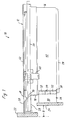
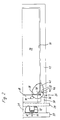
- the base drawer 10 has a one-piece plastic shell 12 which forms both the base 14 and the frame 16 of the drawer.
- a horizontally projecting web 20 is formed to which a front piece 22 is attached.
- a base panel 24 is fastened below the web 20 to the front corners of the frame 16 with the aid of two adapters 26 designed as injection molded plastic parts.
- a slight offset 28 on the underside of the web 20 provides sufficient space for attaching the base panel 24.
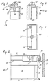
- each of the adapters 26 has a constant, approximately rectangular profile (FIG. 5) and can therefore be cut to the desired length in order to adjust the base recess D (FIG. 1).
- the adapter 26 is tapered in the shape of a roof.
- the roof-shaped area is divided by horizontal slots into upper and lower holding parts 32 and a middle clamping part 34.
- the frame 16 has at its front vertical edges an inclined surface 38 which, like the inclined surfaces of the roof-shaped area of the adapter, forms an angle of 45 ° with the longitudinal axis of the drawer.
- a laterally projecting flange 40 is formed in the extension of the front wall 18, the free end of which is aligned with the side wall 42 of the frame.
- the clamping slot 26 has a relatively large depth in the region of the clamping part 34, so that the clamping part is resiliently connected to the main part 30 of the adapter only via a relatively thin wall 44.
- An obliquely directed screw channel 48 leads from the outer inclined surface 46 of the clamping part 34 with respect to the drawer into the interior of the adapter. With a screw screwed into the screw channel 48, the clamping slot 36 can thus be narrowed in such a way that the flange 40 is firmly clamped.
- corrugations on the flange 40 and on the inner surfaces of the clamping slot 36 the flange 40 is secured against displacement relative to the adapter 26.
- the corrugation is preferably oriented horizontally in at least one of the adapters.
- vertical corrugation can be provided on the other adapter, so that simple and precise adjustment is possible both in height and in the lateral direction.
- the holding parts 32 are essentially rigidly connected to the main part 30 of the adapter according to FIG. 4, since the clamping slot 36 here only extends as far as the middle plane of the adapter.
- the holding parts 32 arranged on both sides of the clamping part 34 protect the clamping part 34 against damage when the clamping connection is subjected to greater stress.
- the adapters 26 When mounting the base panel 24, the adapters 26 are first screwed to the rear of the base panel 24 at a suitable distance, and then the adapters 26 are plugged onto the flanges 40 of the frame 16 from below.
- the frame 16 has an approximately horizontal flange 52 at the upper edge and angled downwards at the outer end, which flange forms a channel on the longitudinal sides of the frame for receiving an extension rail 54.
- the pull-out rail 54 is guided on a running rail 58 fastened to a wall 56 of the furniture body.
- the pull-out rail 54 is locked on the plastic shell 12 of the drawer with the aid of a holding tab 60.
- the adapter 26 is partially outside the plane of the side wall 42 of the frame, but still within the outer edge formed by the free end of the flange 52 of the drawer.
- vertical slots 62 are formed in the end face of the web 20, which are narrowed slightly at their lower end by latching lugs 64, but are otherwise open.
- fastening screws 66 are screwed into the front piece 22 and can be inserted into the slots 62 by overcoming a certain latching resistance between the latching lugs 64.
- the plastic shell 12 forms on the back of the web 20 an inclined surface 68 sloping towards the front wall 18 of the frame.
- the heads of the fastening screws 66 are accessible through openings 70 formed in this inclined surface and closable by plugs.
- the screws 66 are each provided with a washer 72 and have a certain amount of play in the slots 62, so that the front piece 22 can be adjusted both in height and in the lateral direction.
- both the base panel 24 and the front piece 22 can thus be assembled and adjusted in a simple manner.
- Angle strips 74 are injection molded onto the underside of the base 14 of the plastic shell 12, into which a stiffening chipboard base can be inserted.
Landscapes
- Drawers Of Furniture (AREA)
Applications Claiming Priority (2)
| Application Number | Priority Date | Filing Date | Title |
|---|---|---|---|
| DE8903297U | 1989-03-16 | ||
| DE8903297U DE8903297U1 (fr) | 1989-03-16 | 1989-03-16 |
Publications (2)
| Publication Number | Publication Date |
|---|---|
| EP0387494A2 true EP0387494A2 (fr) | 1990-09-19 |
| EP0387494A3 EP0387494A3 (fr) | 1992-10-28 |
Family
ID=6837199
Family Applications (1)
| Application Number | Title | Priority Date | Filing Date |
|---|---|---|---|
| EP19900100897 Withdrawn EP0387494A3 (fr) | 1989-03-16 | 1990-01-17 | Tiroir de soubassement |
Country Status (3)
| Country | Link |
|---|---|
| US (1) | US5013106A (fr) |
| EP (1) | EP0387494A3 (fr) |
| DE (1) | DE8903297U1 (fr) |
Cited By (3)
| Publication number | Priority date | Publication date | Assignee | Title |
|---|---|---|---|---|
| EP1321070A1 (fr) * | 2001-12-20 | 2003-06-25 | Ninkaplast GmbH | Tiroir de soubassement |
| EP1470768A1 (fr) * | 2003-04-16 | 2004-10-27 | Paul Hettich GmbH & Co. KG | Tiroir de soubassement |
| AT500361A1 (de) * | 1999-02-17 | 2005-12-15 | Cleanup Corp | Küchenschrank |
Families Citing this family (7)
| Publication number | Priority date | Publication date | Assignee | Title |
|---|---|---|---|---|
| US5350229A (en) * | 1992-11-13 | 1994-09-27 | Ole Smed | Secure storage desk drawer and installation clamp therefor |
| US5628552A (en) * | 1995-11-20 | 1997-05-13 | O'barr; Terry | Portable multi-compartment drawer |
| DE20120242U1 (de) * | 2001-12-14 | 2002-02-28 | Hettich Paul Gmbh & Co | Bodenseitiger Schubkasten für ein Stellmöbel |
| JP2004091126A (ja) * | 2002-08-30 | 2004-03-25 | Brother Ind Ltd | 給紙カセットおよびそれを備えた画像形成装置 |
| US7458895B2 (en) * | 2002-09-12 | 2008-12-02 | Wms Gaming Inc. | Floating bezel for a peripheral component in a gaming machine |
| US7770985B2 (en) * | 2006-02-15 | 2010-08-10 | Maytag Corporation | Kitchen appliance having floating glass panel |
| GB2449635A (en) * | 2007-05-26 | 2008-12-03 | Anne Irene Keen-Arnold | Pull out drawer located behind the plinth of a cupboard |
Citations (3)
| Publication number | Priority date | Publication date | Assignee | Title |
|---|---|---|---|---|
| FR2257755A1 (fr) * | 1974-01-15 | 1975-08-08 | Teisseire Henry | |
| FR2493691A1 (fr) * | 1980-11-12 | 1982-05-14 | Kaltenbach & Voigt | Armoire, notamment pour des appareillages medicaux et de dentisterie |
| FR2600383A1 (fr) * | 1986-06-20 | 1987-12-24 | Auxiliares Ind | Dispositif d'assemblage reglable pour le panneau frontal du caisson d'un meuble |
Family Cites Families (2)
| Publication number | Priority date | Publication date | Assignee | Title |
|---|---|---|---|---|
| DE8316770U1 (de) * | 1983-06-08 | 1983-11-10 | Ninkaplast Gmbh, 4902 Bad Salzuflen | Auszug fuer schraenke |
| US4624509A (en) * | 1983-10-11 | 1986-11-25 | Myers Industries | Storage drawer |
-
1989
- 1989-03-16 DE DE8903297U patent/DE8903297U1/de not_active Expired
-
1990
- 1990-01-17 EP EP19900100897 patent/EP0387494A3/fr not_active Withdrawn
- 1990-03-13 US US07/492,463 patent/US5013106A/en not_active Expired - Fee Related
Patent Citations (3)
| Publication number | Priority date | Publication date | Assignee | Title |
|---|---|---|---|---|
| FR2257755A1 (fr) * | 1974-01-15 | 1975-08-08 | Teisseire Henry | |
| FR2493691A1 (fr) * | 1980-11-12 | 1982-05-14 | Kaltenbach & Voigt | Armoire, notamment pour des appareillages medicaux et de dentisterie |
| FR2600383A1 (fr) * | 1986-06-20 | 1987-12-24 | Auxiliares Ind | Dispositif d'assemblage reglable pour le panneau frontal du caisson d'un meuble |
Cited By (4)
| Publication number | Priority date | Publication date | Assignee | Title |
|---|---|---|---|---|
| AT500361A1 (de) * | 1999-02-17 | 2005-12-15 | Cleanup Corp | Küchenschrank |
| AT500361B1 (de) * | 1999-02-17 | 2006-12-15 | Cleanup Corp | Küchenschrank |
| EP1321070A1 (fr) * | 2001-12-20 | 2003-06-25 | Ninkaplast GmbH | Tiroir de soubassement |
| EP1470768A1 (fr) * | 2003-04-16 | 2004-10-27 | Paul Hettich GmbH & Co. KG | Tiroir de soubassement |
Also Published As
| Publication number | Publication date |
|---|---|
| US5013106A (en) | 1991-05-07 |
| DE8903297U1 (fr) | 1989-05-03 |
| EP0387494A3 (fr) | 1992-10-28 |
Similar Documents
| Publication | Publication Date | Title |
|---|---|---|
| DE3632442C2 (fr) | ||
| EP1084655B1 (fr) | Système de fixation | |
| DE19647814C2 (de) | Schaltschrank | |
| EP1064707B1 (fr) | Baie destinee a une armoire de distribution | |
| EP0133605B1 (fr) | Liaison d'angle pour armoire | |
| AT398516B (de) | Schubkastenauszug | |
| EP0387494A2 (fr) | Tiroir de soubassement | |
| EP0096898B1 (fr) | Tiroir pour armoires | |
| EP0649617B1 (fr) | Dispositif de fixation notamment pour plinthes pour socles d'armoire | |
| DE3713282A1 (de) | Schublade | |
| DE2625202B2 (de) | Haushaltgerät z.B. Geschirrspülmaschine mit einem frontseitigen Sockelrücksprung | |
| WO1996024236A1 (fr) | Armoire de distribution avec baie et plaque de montage | |
| DE3509703C2 (fr) | ||
| DE3643312C2 (de) | Schubkastenseitenzarge mit vorderendiger Dübelbrücke | |
| DE20307353U1 (de) | Verbindungsbeschlag für Schubladen-Wände | |
| DE102007009667B4 (de) | Profilkonstruktion | |
| EP1463169A2 (fr) | Armoire de distribution et/ou pour un compteur électrique | |
| EP1463170A2 (fr) | Armoire de distribution ou pour compteur électrique | |
| EP0383213A1 (fr) | Support de tablette d'étagère | |
| DE10013026C1 (de) | Wandgehäuse mit Gehäusekorpus und Rückwand | |
| DE3613655C1 (de) | In Moebel,Waende od.dgl. einsetzbare Rastschiene und Verfahren zum Einsetzen einer solchen Rastschiene | |
| DE8217277U1 (de) | Topfauszug | |
| EP3822496A1 (fr) | Dispositif de fixation pour un corps de meuble | |
| DE3546757C2 (en) | Furniture hinge mounting plate | |
| DE3919919A1 (de) | Vorrichtung zum verbinden einer laufschiene mit einer schublade und hierfuer verwendetes winkelstueck |
Legal Events
| Date | Code | Title | Description |
|---|---|---|---|
| PUAI | Public reference made under article 153(3) epc to a published international application that has entered the european phase |
Free format text: ORIGINAL CODE: 0009012 |
|
| AK | Designated contracting states |
Kind code of ref document: A2 Designated state(s): AT BE DE DK ES FR GB GR IT NL SE |
|
| 17P | Request for examination filed |
Effective date: 19901203 |
|
| PUAL | Search report despatched |
Free format text: ORIGINAL CODE: 0009013 |
|
| AK | Designated contracting states |
Kind code of ref document: A3 Designated state(s): AT BE DE DK ES FR GB GR IT NL SE |
|
| STAA | Information on the status of an ep patent application or granted ep patent |
Free format text: STATUS: THE APPLICATION IS DEEMED TO BE WITHDRAWN |
|
| 18D | Application deemed to be withdrawn |
Effective date: 19930429 |