EP0387494A2 - Base sliding drawer - Google Patents
Base sliding drawer Download PDFInfo
- Publication number
- EP0387494A2 EP0387494A2 EP90100897A EP90100897A EP0387494A2 EP 0387494 A2 EP0387494 A2 EP 0387494A2 EP 90100897 A EP90100897 A EP 90100897A EP 90100897 A EP90100897 A EP 90100897A EP 0387494 A2 EP0387494 A2 EP 0387494A2
- Authority
- EP
- European Patent Office
- Prior art keywords
- drawer
- base
- adapter
- frame
- web
- Prior art date
- Legal status (The legal status is an assumption and is not a legal conclusion. Google has not performed a legal analysis and makes no representation as to the accuracy of the status listed.)
- Withdrawn
Links
- 239000004033 plastic Substances 0.000 claims abstract description 9
- 238000002347 injection Methods 0.000 claims description 3
- 239000007924 injection Substances 0.000 claims description 3
- 230000006978 adaptation Effects 0.000 abstract 1
- 238000010276 construction Methods 0.000 abstract 1
- 238000001746 injection moulding Methods 0.000 abstract 1
- 230000007704 transition Effects 0.000 description 3
- 230000006378 damage Effects 0.000 description 2
- 208000027418 Wounds and injury Diseases 0.000 description 1
- 239000011093 chipboard Substances 0.000 description 1
- 238000006073 displacement reaction Methods 0.000 description 1
- 230000002349 favourable effect Effects 0.000 description 1
- 208000014674 injury Diseases 0.000 description 1
- 238000009434 installation Methods 0.000 description 1
- 239000002991 molded plastic Substances 0.000 description 1
- 239000000243 solution Substances 0.000 description 1
- 239000002023 wood Substances 0.000 description 1
Images
Classifications
-
- A—HUMAN NECESSITIES
- A47—FURNITURE; DOMESTIC ARTICLES OR APPLIANCES; COFFEE MILLS; SPICE MILLS; SUCTION CLEANERS IN GENERAL
- A47B—TABLES; DESKS; OFFICE FURNITURE; CABINETS; DRAWERS; GENERAL DETAILS OF FURNITURE
- A47B91/00—Feet for furniture in general
- A47B91/005—Support bases
-
- A—HUMAN NECESSITIES
- A47—FURNITURE; DOMESTIC ARTICLES OR APPLIANCES; COFFEE MILLS; SPICE MILLS; SUCTION CLEANERS IN GENERAL
- A47B—TABLES; DESKS; OFFICE FURNITURE; CABINETS; DRAWERS; GENERAL DETAILS OF FURNITURE
- A47B88/00—Drawers for tables, cabinets or like furniture; Guides for drawers
- A47B88/90—Constructional details of drawers
- A47B88/944—Drawers characterised by the front panel
-
- A—HUMAN NECESSITIES
- A47—FURNITURE; DOMESTIC ARTICLES OR APPLIANCES; COFFEE MILLS; SPICE MILLS; SUCTION CLEANERS IN GENERAL
- A47B—TABLES; DESKS; OFFICE FURNITURE; CABINETS; DRAWERS; GENERAL DETAILS OF FURNITURE
- A47B2210/00—General construction of drawers, guides and guide devices
- A47B2210/16—Sliding drawers being part of the furniture base
-
- A—HUMAN NECESSITIES
- A47—FURNITURE; DOMESTIC ARTICLES OR APPLIANCES; COFFEE MILLS; SPICE MILLS; SUCTION CLEANERS IN GENERAL
- A47B—TABLES; DESKS; OFFICE FURNITURE; CABINETS; DRAWERS; GENERAL DETAILS OF FURNITURE
- A47B88/00—Drawers for tables, cabinets or like furniture; Guides for drawers
- A47B88/40—Sliding drawers; Slides or guides therefor
- A47B88/413—Drawers slidable into a space provided between furniture body and floor, e.g. plinth drawers
Definitions
- the invention relates to a base drawer according to the preamble of claim 1.
- Socket drawers of this type are used, for example, in base cabinets in kitchens and make it possible to use the free space remaining under the actual oven in the base cabinet. By using the base area of the base cabinet, a sufficient drawer depth is achieved.
- the base drawer has on the front in the upper area a usual drawer front piece, which is in one level with the front of the base cabinet and with the fronts of the neighboring kitchen furniture.
- a plinth cover In the lower area of the plinth drawer, on the other hand, there is a plinth cover, which is offset backwards from the front piece and is flush with the plinth covers of the adjacent furniture.
- Socket drawers made of wood are known in which the plinth is screwed onto the front wall of the actual drawer, while the front piece is attached to a web projecting forward from the upper edge of the drawer.
- the invention is therefore based on the object of a base drawer create that can be easily integrated into the respective furniture program.
- two attachable adapters made of plastic are provided for fastening the base panel and are held in a clamped manner on the drawer.
- the base recess can thus be set in a simple manner by using adapters of a suitable length or by cutting the adapters to a suitable length.
- the clamp attachment of the adapter to the drawer enables easy installation.
- the adapter and the associated fastening devices on the drawer are covered by the base panel, the front piece and the web of the drawer, so that they do not disturb the appearance.
- the adapters can be designed so that they grip around the front part of the actual drawer in a fork-shaped manner and are clamped from the outside against the side walls of the drawer. This type of fastening enables easy adjustment of the height of the base panel. If necessary, the clamping force can be increased by transverse clamping screws and an adjustment of the base panel in the lateral direction can also be made possible.
- each adapter is preferably provided with a clamping slot running parallel to the plane of the base panel, into which a flange fixedly attached to the drawer can be clamped.
- the adapter is preferably tapered like a roof at its end facing the drawer, and the drawer is provided on its front vertical edges with bevels which correspond to the inclined surfaces of the roof-shaped regions of the adapters. Seen from the front, the adapters are half inside and half outside the cross section of the drawer.
- the clamping slots of the adapters are located at the transition point between the roof-shaped area and the main part of the adapter and each take up a flange that projects laterally in the extension of the front wall of the drawer.
- the roof-shaped part of the adapter forms a clamping tab, which is countered by a screw that is accessible from the outer inclined surface of the adapter the flange is clampable.
- the screws for attaching the adapter to the sock panel are also accessible from this inclined surface and run in the parts of the adapter that are outside the drawer cross section.
- the web serving for fastening the drawer front piece and the drawer frame are made in one piece from plastic, and the web is provided on its front wall facing the front piece with at least two open slots at one end for receiving fastening screws screwed into the front piece. Openings are formed in the back of the web facing the inside of the drawer, through which the heads of the fastening screws are accessible.
- the front piece can be adjusted in height and laterally.
- the web On its rear side, the web preferably has an inclined surface that slopes away from the upper edge toward the inside of the drawer and in which the openings for the fastening screws are located.
- the fastening screws are easier to reach with the screwdriver, and the inclined surface also provides a transition that is both optically and functionally favorable between the web and the interior of the drawer.
- the open ends of the slots for the fastening screws are preferably narrowed by latching lugs, so that the front piece can be latched onto the web with the fastening screws screwed in and temporarily held as long as the fastening screws are not tightened.
- the base drawer 10 has a one-piece plastic shell 12 which forms both the base 14 and the frame 16 of the drawer.
- a horizontally projecting web 20 is formed to which a front piece 22 is attached.
- a base panel 24 is fastened below the web 20 to the front corners of the frame 16 with the aid of two adapters 26 designed as injection molded plastic parts.
- a slight offset 28 on the underside of the web 20 provides sufficient space for attaching the base panel 24.
- each of the adapters 26 has a constant, approximately rectangular profile (FIG. 5) and can therefore be cut to the desired length in order to adjust the base recess D (FIG. 1).
- the adapter 26 is tapered in the shape of a roof.
- the roof-shaped area is divided by horizontal slots into upper and lower holding parts 32 and a middle clamping part 34.
- the frame 16 has at its front vertical edges an inclined surface 38 which, like the inclined surfaces of the roof-shaped area of the adapter, forms an angle of 45 ° with the longitudinal axis of the drawer.
- a laterally projecting flange 40 is formed in the extension of the front wall 18, the free end of which is aligned with the side wall 42 of the frame.
- the clamping slot 26 has a relatively large depth in the region of the clamping part 34, so that the clamping part is resiliently connected to the main part 30 of the adapter only via a relatively thin wall 44.
- An obliquely directed screw channel 48 leads from the outer inclined surface 46 of the clamping part 34 with respect to the drawer into the interior of the adapter. With a screw screwed into the screw channel 48, the clamping slot 36 can thus be narrowed in such a way that the flange 40 is firmly clamped.
- corrugations on the flange 40 and on the inner surfaces of the clamping slot 36 the flange 40 is secured against displacement relative to the adapter 26.
- the corrugation is preferably oriented horizontally in at least one of the adapters.
- vertical corrugation can be provided on the other adapter, so that simple and precise adjustment is possible both in height and in the lateral direction.
- the holding parts 32 are essentially rigidly connected to the main part 30 of the adapter according to FIG. 4, since the clamping slot 36 here only extends as far as the middle plane of the adapter.
- the holding parts 32 arranged on both sides of the clamping part 34 protect the clamping part 34 against damage when the clamping connection is subjected to greater stress.
- the adapters 26 When mounting the base panel 24, the adapters 26 are first screwed to the rear of the base panel 24 at a suitable distance, and then the adapters 26 are plugged onto the flanges 40 of the frame 16 from below.
- the frame 16 has an approximately horizontal flange 52 at the upper edge and angled downwards at the outer end, which flange forms a channel on the longitudinal sides of the frame for receiving an extension rail 54.
- the pull-out rail 54 is guided on a running rail 58 fastened to a wall 56 of the furniture body.
- the pull-out rail 54 is locked on the plastic shell 12 of the drawer with the aid of a holding tab 60.
- the adapter 26 is partially outside the plane of the side wall 42 of the frame, but still within the outer edge formed by the free end of the flange 52 of the drawer.
- vertical slots 62 are formed in the end face of the web 20, which are narrowed slightly at their lower end by latching lugs 64, but are otherwise open.
- fastening screws 66 are screwed into the front piece 22 and can be inserted into the slots 62 by overcoming a certain latching resistance between the latching lugs 64.
- the plastic shell 12 forms on the back of the web 20 an inclined surface 68 sloping towards the front wall 18 of the frame.
- the heads of the fastening screws 66 are accessible through openings 70 formed in this inclined surface and closable by plugs.
- the screws 66 are each provided with a washer 72 and have a certain amount of play in the slots 62, so that the front piece 22 can be adjusted both in height and in the lateral direction.
- both the base panel 24 and the front piece 22 can thus be assembled and adjusted in a simple manner.
- Angle strips 74 are injection molded onto the underside of the base 14 of the plastic shell 12, into which a stiffening chipboard base can be inserted.
Abstract
Description
Die Erfindung betrifft einen Sockelschubkasten gemäß dem Oberbegriff des Anspruchs 1.The invention relates to a base drawer according to the preamble of
Derartige Sockelschubkästen werden beispielsweise in Herd-Unterschränke in Küchen eingesetzt und ermöglichen es, den unter dem eigentlichen Herd in dem Unterschrank verbleibenden Freiraum zu nutzen. Durch Ausnutzung des Sockelbereiches des Unterschrankes wird dabei eine ausreichende Schubkastentiefe erreicht.Socket drawers of this type are used, for example, in base cabinets in kitchens and make it possible to use the free space remaining under the actual oven in the base cabinet. By using the base area of the base cabinet, a sufficient drawer depth is achieved.
Der Sockelschubkasten weist an seiner Vorderseite im oberen Bereich ein übliches Schubkasten-Vorderstück auf, das mit der Front des Unterschrankes und mit den Fronten der benachbarten Küchenmöbel in einer Ebene liegt. Im unteren Bereich des Sockelschubkastens ist dagegen eine Sockelblende angebracht, die gegenüber dem Vorderstück nach rückwarts versetzt ist und mit den Sockelblenden der angrenzenden Möbel fluchtet.The base drawer has on the front in the upper area a usual drawer front piece, which is in one level with the front of the base cabinet and with the fronts of the neighboring kitchen furniture. In the lower area of the plinth drawer, on the other hand, there is a plinth cover, which is offset backwards from the front piece and is flush with the plinth covers of the adjacent furniture.
Es sind Sockelschubkästen aus Holz bekannt, bei denen die Sockelblende an die vordere Wand des eigentlichen Schubkastens angeschraubt ist, während das Vorderstück an einen vom oberen Rand des Schubkastens nach vorn vorspringenden Steg angedübelt ist.Socket drawers made of wood are known in which the plinth is screwed onto the front wall of the actual drawer, while the front piece is attached to a web projecting forward from the upper edge of the drawer.
Bei gewöhnlichen Schubkästen, die nicht als Sockelschubkasten ausgebildet sind, besteht vielfach die Möglichkeit, das Vorderstück nachträglich in der Höhe und in seitlicher Richtung zu justieren, um eine exakte Ausrichtung mit den Vorderstücken der benachbarten Möbelteile zu erreichen. Die hierzu erforderlichen Beschläge sind beispielsweise in den vorderen Enden der Seitenwände des Schubkastens untergebracht. Bei herkömmlichen Sockelschubkästen, bei denen das Vorderstück an dem vorspringenden Steg angebracht ist, besteht eine solche Justiermöglichkeit nicht. Auch die exakte Ausrichtung und Justierung der Sockelblenden ist bei herkömmlichen Sockelschubkästen relativ umständlich und schwierig, zumal oftmals nicht nur eine Anpassung in der Höhe und in Querrichtung, sondern auch in der Tiefe erforderlich ist, da der Versatz zwischen dem Vorderstück und der Sockelblende, der sogenannte Sockelrücksprung, bei Möbelprogrammen verschiedener Frabikate unterschiedlich ausfällt.With ordinary drawers, which are not designed as base drawers, there is often the possibility of subsequently adjusting the height of the front piece and in the lateral direction in order to achieve an exact alignment with the front pieces of the neighboring furniture parts. The fittings required for this are housed, for example, in the front ends of the side walls of the drawer. In conventional plinth drawers in which the front piece is attached to the projecting web, there is no such adjustment possibility. The exact alignment and adjustment of the plinth panels is also relatively cumbersome and difficult with conventional plinth drawers, especially since often not only an adjustment in height and in the transverse direction, but also in depth is required, since the offset between the front piece and the plinth panel, the so-called Plinth recess, different for furniture programs of different brands.
Der Erfindung liegt daher die Aufgabe zugrunde, einen Sockelschubkasten zu schaffen, der sich auf einfache Weise in das jeweilige Möbelprogramm einpassen läßt.The invention is therefore based on the object of a base drawer create that can be easily integrated into the respective furniture program.
Erfindungsgemäße Lösungen dieser Aufgabe sind in den Ansprüchen 1 und 12 angegeben. Weitere Ausgestaltungen der Erfindung ergeben sich aus den Unteransprüchen.Solutions to this object according to the invention are specified in
Gemäß Anspruch 1 sind zur Befestigung der Sockelblende zwei an der Sockelblende befestigbare Adapter aus Kunststoff vorgesehen, die klemmend an dem Schubkasten gehalten sind. Der Sockelrücksprung kann somit auf einfache Weise eingestellt werden, indem Adapter geeigneter Länge verwendet bzw. die Adapter auf geeignete Länge abgeschnitten werden. Durch die Klemmbefestigung der Adapter am Schubkasten wird ein einfache Montage ermöglicht. Die Adapter und die zugehörigen Befestigungseinrichtungen am Schubkasten sind durch die Sockelblende, das Vorderstück und den Steg des Schubkastens verdeckt, so daß sie das Erscheinungsbild nicht stören.According to
Die Adapter können so gestaltet sein, daß sie den vorderen Teil des eigentlichen Schubkastens gabelförmig umgreifen und von außen gegen die Seitenwände des Schubkastens gespannt sind. Diese Befestigungsart ermöglicht eine einfache Justierung der Höhe der Sockelblende. Gegebenenfalls kann durch quergerichtete Spannschrauben die Klemmkraft erhöht und zusätzlich eine Justierung der Sockelblende in seitlicher Richtung ermöglicht werden.The adapters can be designed so that they grip around the front part of the actual drawer in a fork-shaped manner and are clamped from the outside against the side walls of the drawer. This type of fastening enables easy adjustment of the height of the base panel. If necessary, the clamping force can be increased by transverse clamping screws and an adjustment of the base panel in the lateral direction can also be made possible.
Bevorzugt ist jedoch jeder Adapter mit einem parallel zur Ebene der Sockelblende verlaufenden Klemmschlitz versehen, in den ein fest am Schubkasten angebrachter Flansch einspannbar ist. In diesem Fall können die Höhen- und Seitenjustierung in einem Arbeitsgang vorgenommen werden. Vorzugsweise ist der Adapter im Grundriß gesehen an seinem dem Schubkasten zugewandten Ende dachförmig zugespitzt, und der Schubkasten ist an seinen vorderen vertikalen Kanten mit Abschrägungen versehen, die den Schrägflächen der dachförmigen Bereiche der Adapter entsprechen. Die Adapter liegen somit von vorn gesehen jeweils zur Hälfte innerhalb und zur anderen Hälfte außerhalb des Querschnitts des Schubkastens. Die Klemmschlitze der Adapter befinden sich an der Übergangsstelle zwischen dem dachförmigen Bereich und dem Hauptteil des Adapters und nehmen jeweils einen Flansch auf, der in Verlängerung der vorderen Wand des Schubkastens seitlich vorspringt. Der dachförmige Teil des Adaptes bildet eine Klemmlasche, die mittels einer von der äußeren Schrägfläche des Adapters her zugänglichen Schraube gegen den Flansch spannbar ist. Die Schrauben zur Befestigung des Adapters an der Sockenblende sind ebenfalls von dieser Schrägfläche aus zugänglich und verlaufen in den außerhalb des Schubkastenquerschnitts liegenden Teilen des Adapters. Durch diese Gestaltung der Adapter und der Klemmbefestigungen wird eine einfache Montage und eine kompakte Bauweise erreicht, und es werden verletzungsgefährliche scharfe Ecken im Übergangsbereich zwischen Schubkasten und Adapter vermieden.However, each adapter is preferably provided with a clamping slot running parallel to the plane of the base panel, into which a flange fixedly attached to the drawer can be clamped. In this case, the height and side adjustment can be done in one operation. The adapter is preferably tapered like a roof at its end facing the drawer, and the drawer is provided on its front vertical edges with bevels which correspond to the inclined surfaces of the roof-shaped regions of the adapters. Seen from the front, the adapters are half inside and half outside the cross section of the drawer. The clamping slots of the adapters are located at the transition point between the roof-shaped area and the main part of the adapter and each take up a flange that projects laterally in the extension of the front wall of the drawer. The roof-shaped part of the adapter forms a clamping tab, which is countered by a screw that is accessible from the outer inclined surface of the adapter the flange is clampable. The screws for attaching the adapter to the sock panel are also accessible from this inclined surface and run in the parts of the adapter that are outside the drawer cross section. This design of the adapter and the clamp fastenings enables simple assembly and a compact design, and sharp corners in the transition area between the drawer and adapter which are dangerous to injury are avoided.
Gemäß Anspruch 12 sind der zur Befestigung des Schubkasten-Vorderstücks dienende Steg und die Schubkastenzarge einstückig aus Kunststoff hergestellt, und der Steg ist an seiner dem Vorderstück zugewandten Stirnwand mit wenigstens zwei an einem Ende offenen Schlitzen zur Aufnahme von in das Vorderstück eingeschraubten Befestigungsschrauben versehen. In der dem Schubkasteninneren zugewandten Rückseite des Steges sind Öffnungen ausgebildet, durch die die Köpfe der Befestigungsschrauben zugänglich sind. Auf diese Weise wird eine einfache, lösbare Befestigung des Vorderstücks ermöglicht, und aufgrund eines gewissen Spiels der Befestigungsschrauben in den Schlitzen kann das Vorderstück in der Höhe und seitlich justiert werden. Der Steg weist auf seiner Rückseite vorzugsweise eine vom oberen Rand zum Schubkasteninneren hin abfallende Schrägfläche auf, in der sich die Öffnungen für die Befestigungsschrauben befinden. Aufgrund der Schrägfläche sind die Befestigungsschrauben besser mit dem Schraubenzieher erreichbar, und darüber hinaus wird durch die Schrägfläche ein sowohl optisch als auch funktionell günstiger Übergang zwischen dem Steg und dem Inneren des Schubkastens erreicht. Die offenen Enden der Schlitze für die Befestigungsschrauben sind vorzugsweise durch Rastnasen verengt, so daß das Vorderstück mit eingeschraubten Befestigungsschrauben an dem Steg verrastet und provisorisch gehalten werden kann, solange die Befestigungsschrauben nicht fest angezogen sind.According to
Im folgenden wird ein bevorzugtes Ausführungsbeispiel der Erfindung anhand der Zeichnungen näher erläutert.A preferred exemplary embodiment of the invention is explained in more detail below with reference to the drawings.
Es zeigen:
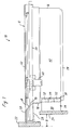
- Fig. 1 eine Seitenansicht eines Sockelschubkastens;
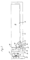
- Fig. 2 den seitlichen Randbereich des Schubkastens in der Draufsicht;
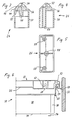
- Fig. 3 und 4 Schnitte durch einen Adapter zur Befestigung einer Sockelblende;
- Fig. 5 eine Stirnansicht des Adapters; und
- Fig. 6 eine Frontansicht des Schubkastens ohne Vorderstück und Sockelblende.
- Figure 1 is a side view of a base drawer.
- 2 shows the side edge region of the drawer in a top view;
- Figures 3 and 4 sections through an adapter for attaching a base panel.
- 5 is an end view of the adapter; and
- Fig. 6 is a front view of the drawer without front piece and base panel.
Gemäß Figuren 1 und 2 weist der Sockelschubkasten 10 eine einstückige Kunststoffschale 12 auf, die sowohl den Boden 14 als auch die Zarge 16 des Schubkastens bildet. Am oberen Ende der vorderen Wand 18 der Zarge ist ein waagerecht nach vorn vorspringender Steg 20 ausgebildet an dem ein Vorderstück 22 befestigt ist. Eine Sockelblende 24 ist mit Hilfe zweier als Kunststoff-Spritzteile ausgebildeter Adapter 26 unterhalb das Steges 20 an den vorderen Ecken der Zarge 16 befestigt. Durch eine leichte Kröpfung 28 an der Unterseite des Steges 20 wird ein ausreichender Freiraum zur Anbringung der Sockelblende 24 gebildet.According to FIGS. 1 and 2, the
Jeder der Adapter 26 weist in seinem Hauptteil ein gleichbleibendes etwa rechteckiges Profil auf (Figur 5) und kann somit zur Einstellung des Sockelrücksprungs D (Figur 1) auf die jeweils gewünschte Länge abgeschnitten werden. An seinem der Zarge 16 zugewandten Ende ist der Adapter 26 im Grundriß dachförmig zugespitzt. Der dachförmige Bereich ist durch waagerechte Schlitze in obere und untere Halteteile 32 und einen mittleren Klemmteil 34 unterteilt. Die Halte- und Klemmteile begrenzen zusammen mit dem Hauptteil 30 des Adapters einen zur vorderen Wand 18 der Zarge hin offenen Klemmschlitz 36.The main part of each of the
Die Zarge 16 weist an ihren vorderen vertikalen Kanten jeweils eine Schrägfläche 38 auf, die ebenso wie die Schrägflächen des dachförmigen Bereiches des Adapters einen Winkel von 45° mit der Längsachse des Schubkastens bildet. An der Zarge 16 ist ein seitlich in Verlängerung der vorderen Wand 18 vorspringender Flansch 40 ausgebildet, dessen freies Ende mit der Seitenwand 42 der Zarge fluchtet. Durch Eingriff des Flansches 40 in den Klemmschlitz 36 wird der Adapter 26 klemmend an der Zarge 16 gehalten. Der Abstand der an beiden Enden der Sockelblende 24 angebrachten Adapter 26 ist so bemessen, daß die Flansche 40 in Richtung der Tiefe der Klemmschlitze ein gewisses Spiel aufweisen, so daß die Sockelblende 24 sowohl in seitlicher Richtung als auch in vertikaler Richtung justiert werden kann.The
Gemäß Figur 3 weist der Klemmschlitz 26 im Bereich des Klemmteils 34 eine relativ große Tiefe auf, so daß das Klemmteil lediglich über eine verhältnismäßig dünne Wand 44 federnd mit dem Hauptteil 30 des Adapters verbunden ist. Von der in Bezug auf den Schubkasten äußeren Schrägfläche 46 des Klemmteils 34 führt ein schräg gerichteter Schraubenkanal 48 in das Innere des Adapters. Mit einer in den Schraubenkanal 48 eingeschraubten Schraube kann somit der Klemmschlitz 36 derart verengt werden, daß der Flansch 40 fest eingespannt wird. Durch nicht gezeigte Riffelungen an dem Flansch 40 und an den Innenflächen des Klemmschlitzes 36 wird der Flansch 40 gegen Verschiebung relativ zu dem Adapter 26 gesichert. Die Riffelung ist vorzugsweise wenigstens bei einem der Adapter waagerecht orientiert. An dem anderen Adapter kann dagegen eine vertikale Riffelung vorgesehen sein, so daß eine einfache und genaue Justierung sowohl in der Höhe als auch in seitlicher Richtung ermöglicht wird.According to FIG. 3, the
Die Halteteile 32 sind gemäß Figur 4 im wesentlichen starr mit dem Hauptteil 30 des Adapters verbunden, da der Klemmschlitz 36 hier etwa nur bis zur Mittelebene des Adapters reicht. Durch die beiderseits des Klemmteils 34 angeordneten Halteteile 32 wird das Klemmteil 34 bei stärkerer Beanspruchung der Klemmverbindung gegen Beschädigung geschützt. In der nicht durch den Klemmschlitz 36 unterbrochenen Hälfte des Adapters ist im Bereich der Halteteile 32 jeweils ein parallel zur Längsachse des Adapters verlaufender Schraubenkanal 50 für eine Schraube zur Befestigung des Adapters an der Sockelblende 24 ausgebildet.The
Bei der Montage der Sockelblende 24 werden die Adapter 26 zunächst in geeignetem Abstand an die Rückseite der Sockelblende 24 angeschraubt, und anschließend werden die Adapter 26 von unten auf die Flansche 40 der Zarge 16 aufgesteckt.When mounting the
Gemäß Figur 6 weist die Zarge 16 am oberen Rand einen etwa waagerecht verlaufenden und am äußeren Ende nach unten abgewinkelten Flansch 52 auf, der an den Längsseiten der Zarge einen Kanal zur Aufnahme einer Auszugschiene 54 bildet. Die Auszugschiene 54 ist auf einer an einer Wand 56 des Möbelkorpus befestigten Laufschiene 58 geführt. Mit Hilfe einer Haltelasche 60 ist die Auszugschiene 54 an der Kunststoffschale 12 des Schubkastens verrastet. Wie in Figur 2 zu erkennen ist, liegt der Adapter 26 zwar teilweise außerhalb der Ebene der Seitenwand 42 der Zarge, jedoch noch innerhalb des durch das freie Ende des Flansches 52 gebildeten äußeren Randes des Schubkastens.According to FIG. 6, the
In der Stirnfläche des Steges 20 sind gemäß Figur 6 vertikale Schlitze 62 ausgebildet, die an ihrem unteren Ende zwar durch Rastnasen 64 leicht verengt, im übrigen jedoch offen sind. In das Vorderstück 22 sind gemäß Figur 2 Befestigungsschrauben 66 eingeschraubt, die sich unter Überwindung eines gewissen Rastwiderstandes zwischen den Rastnasen 64 hindurch in die Schlitze 62 einführen lassen.According to FIG. 6,
Die Kunststoffschale 12 bildet auf der Rückseite des Steges 20 eine zu der vorderen Wand 18 der Zarge hin abfallende Schrägfläche 68. Die Köpfe der Befestigungsschrauben 66 sind durch in dieser Schrägfläche gebildete, durch Stopfen verschließbare Öffnungen 70 zugänglich. Die Schrauben 66 sind jeweils mit einer Unterlegscheibe 72 versehen und weisen in den Schlitzen 62 ein gewisses Spiel auf, so daß das Vorerstück 22 sowohl in der Höhe als auch in seitlicher Richtung justiert werden kann.The
Bei dem oben beschriebenen Schubkasten lassen sich somit sowohl die Sockelblende 24 als auch das Vorderstück 22 auf einfache Weise montieren und justieren.In the drawer described above, both the
An die Unterseite des Bodens 14 der Kunststoffschale 12 sind Winkelleisten 74 angespritzt, in die ein versteifender Spanplattenboden eingeschoben werden kann.Angle strips 74 are injection molded onto the underside of the
Claims (16)
Applications Claiming Priority (2)
| Application Number | Priority Date | Filing Date | Title |
|---|---|---|---|
| DE8903297U DE8903297U1 (en) | 1989-03-16 | 1989-03-16 | |
| DE8903297U | 1989-03-16 |
Publications (2)
| Publication Number | Publication Date |
|---|---|
| EP0387494A2 true EP0387494A2 (en) | 1990-09-19 |
| EP0387494A3 EP0387494A3 (en) | 1992-10-28 |
Family
ID=6837199
Family Applications (1)
| Application Number | Title | Priority Date | Filing Date |
|---|---|---|---|
| EP19900100897 Withdrawn EP0387494A3 (en) | 1989-03-16 | 1990-01-17 | Base sliding drawer |
Country Status (3)
| Country | Link |
|---|---|
| US (1) | US5013106A (en) |
| EP (1) | EP0387494A3 (en) |
| DE (1) | DE8903297U1 (en) |
Cited By (3)
| Publication number | Priority date | Publication date | Assignee | Title |
|---|---|---|---|---|
| EP1321070A1 (en) * | 2001-12-20 | 2003-06-25 | Ninkaplast GmbH | Cabinet base sliding drawer |
| EP1470768A1 (en) * | 2003-04-16 | 2004-10-27 | Paul Hettich GmbH & Co. KG | Cabinet base drawer |
| AT500361A1 (en) * | 1999-02-17 | 2005-12-15 | Cleanup Corp | cupboard |
Families Citing this family (7)
| Publication number | Priority date | Publication date | Assignee | Title |
|---|---|---|---|---|
| US5350229A (en) * | 1992-11-13 | 1994-09-27 | Ole Smed | Secure storage desk drawer and installation clamp therefor |
| US5628552A (en) * | 1995-11-20 | 1997-05-13 | O'barr; Terry | Portable multi-compartment drawer |
| DE20120242U1 (en) * | 2001-12-14 | 2002-02-28 | Hettich Paul Gmbh & Co | Bottom drawer for a piece of furniture |
| JP2004091126A (en) * | 2002-08-30 | 2004-03-25 | Brother Ind Ltd | Paper feed cassette and image forming device therewith |
| US7458895B2 (en) * | 2002-09-12 | 2008-12-02 | Wms Gaming Inc. | Floating bezel for a peripheral component in a gaming machine |
| US7770985B2 (en) * | 2006-02-15 | 2010-08-10 | Maytag Corporation | Kitchen appliance having floating glass panel |
| GB2449635A (en) * | 2007-05-26 | 2008-12-03 | Anne Irene Keen-Arnold | Pull out drawer located behind the plinth of a cupboard |
Citations (3)
| Publication number | Priority date | Publication date | Assignee | Title |
|---|---|---|---|---|
| FR2257755A1 (en) * | 1974-01-15 | 1975-08-08 | Teisseire Henry | |
| FR2493691A1 (en) * | 1980-11-12 | 1982-05-14 | Kaltenbach & Voigt | CABINET, ESPECIALLY FOR MEDICAL AND DENTISTRY DEVICES |
| FR2600383A1 (en) * | 1986-06-20 | 1987-12-24 | Auxiliares Ind | Adjustable assembly device for the front panel of the box element of an item of furniture |
Family Cites Families (2)
| Publication number | Priority date | Publication date | Assignee | Title |
|---|---|---|---|---|
| DE8316770U1 (en) * | 1983-06-08 | 1983-11-10 | Ninkaplast Gmbh, 4902 Bad Salzuflen | EXTENSION FOR CABINETS |
| US4624509A (en) * | 1983-10-11 | 1986-11-25 | Myers Industries | Storage drawer |
-
1989
- 1989-03-16 DE DE8903297U patent/DE8903297U1/de not_active Expired
-
1990
- 1990-01-17 EP EP19900100897 patent/EP0387494A3/en not_active Withdrawn
- 1990-03-13 US US07/492,463 patent/US5013106A/en not_active Expired - Fee Related
Patent Citations (3)
| Publication number | Priority date | Publication date | Assignee | Title |
|---|---|---|---|---|
| FR2257755A1 (en) * | 1974-01-15 | 1975-08-08 | Teisseire Henry | |
| FR2493691A1 (en) * | 1980-11-12 | 1982-05-14 | Kaltenbach & Voigt | CABINET, ESPECIALLY FOR MEDICAL AND DENTISTRY DEVICES |
| FR2600383A1 (en) * | 1986-06-20 | 1987-12-24 | Auxiliares Ind | Adjustable assembly device for the front panel of the box element of an item of furniture |
Cited By (4)
| Publication number | Priority date | Publication date | Assignee | Title |
|---|---|---|---|---|
| AT500361A1 (en) * | 1999-02-17 | 2005-12-15 | Cleanup Corp | cupboard |
| AT500361B1 (en) * | 1999-02-17 | 2006-12-15 | Cleanup Corp | cupboard |
| EP1321070A1 (en) * | 2001-12-20 | 2003-06-25 | Ninkaplast GmbH | Cabinet base sliding drawer |
| EP1470768A1 (en) * | 2003-04-16 | 2004-10-27 | Paul Hettich GmbH & Co. KG | Cabinet base drawer |
Also Published As
| Publication number | Publication date |
|---|---|
| US5013106A (en) | 1991-05-07 |
| EP0387494A3 (en) | 1992-10-28 |
| DE8903297U1 (en) | 1989-05-03 |
Similar Documents
| Publication | Publication Date | Title |
|---|---|---|
| DE3632442C2 (en) | ||
| EP1084655B1 (en) | Fastening assembly | |
| DE19647814C2 (en) | switch cabinet | |
| EP0133605B1 (en) | Corner connection for a cupboard | |
| AT398516B (en) | DRAWER EXTENSION | |
| EP0387494A2 (en) | Base sliding drawer | |
| EP0096898B1 (en) | Drawer for cabinets | |
| EP0649617B1 (en) | Fastening device especially for cupboard-bases plinths | |
| DE3713282A1 (en) | DRAWER | |
| DE2625202B2 (en) | Household appliance, e.g. dishwasher, with a base recess on the front | |
| EP0807371A1 (en) | Switch cabinet with rack and mounting plate | |
| DE3509703C2 (en) | ||
| DE3643312C2 (en) | Drawer side frame with front-mounted dowel bridge | |
| DE20307353U1 (en) | Fitting for a sliding drawer, to lock the rear wall to the side walls, has matching structures at the fitting and the wall to lock together in a positive fit and be secured by fastening screws | |
| DE102007009667B4 (en) | profile construction | |
| EP1463169A2 (en) | Meter and/or distribution cabinet | |
| EP1463170A2 (en) | Meter- or distribution cabinet | |
| EP0383213A1 (en) | Console support | |
| DE10013026C1 (en) | Wall-mounted housing secured to wall surface via fixing blocks received in fixing sockets adjacent top and bottom edges of housing body rear wall | |
| EP3533944B1 (en) | Deck construction for a water outlet with adjustable cover suspension | |
| DE3919919C2 (en) | ||
| DE3613655C1 (en) | In furniture, walls or the like. insertable locking rail and method for inserting such a locking rail | |
| DE8217277U1 (en) | POT EXTRACT | |
| EP3822496A1 (en) | Fastening device for a furniture body | |
| DE3546757C2 (en) | Furniture hinge mounting plate |
Legal Events
| Date | Code | Title | Description |
|---|---|---|---|
| PUAI | Public reference made under article 153(3) epc to a published international application that has entered the european phase |
Free format text: ORIGINAL CODE: 0009012 |
|
| AK | Designated contracting states |
Kind code of ref document: A2 Designated state(s): AT BE DE DK ES FR GB GR IT NL SE |
|
| 17P | Request for examination filed |
Effective date: 19901203 |
|
| PUAL | Search report despatched |
Free format text: ORIGINAL CODE: 0009013 |
|
| AK | Designated contracting states |
Kind code of ref document: A3 Designated state(s): AT BE DE DK ES FR GB GR IT NL SE |
|
| STAA | Information on the status of an ep patent application or granted ep patent |
Free format text: STATUS: THE APPLICATION IS DEEMED TO BE WITHDRAWN |
|
| 18D | Application deemed to be withdrawn |
Effective date: 19930429 |