EP1470768A1 - Cabinet base drawer - Google Patents
Cabinet base drawer Download PDFInfo
- Publication number
- EP1470768A1 EP1470768A1 EP04400008A EP04400008A EP1470768A1 EP 1470768 A1 EP1470768 A1 EP 1470768A1 EP 04400008 A EP04400008 A EP 04400008A EP 04400008 A EP04400008 A EP 04400008A EP 1470768 A1 EP1470768 A1 EP 1470768A1
- Authority
- EP
- European Patent Office
- Prior art keywords
- drawer
- base
- area
- side walls
- panel
- Prior art date
- Legal status (The legal status is an assumption and is not a legal conclusion. Google has not performed a legal analysis and makes no representation as to the accuracy of the status listed.)
- Granted
Links
Images


Classifications
-
- A—HUMAN NECESSITIES
- A47—FURNITURE; DOMESTIC ARTICLES OR APPLIANCES; COFFEE MILLS; SPICE MILLS; SUCTION CLEANERS IN GENERAL
- A47B—TABLES; DESKS; OFFICE FURNITURE; CABINETS; DRAWERS; GENERAL DETAILS OF FURNITURE
- A47B95/00—Fittings for furniture
- A47B95/002—Plinths, e.g. between furniture and ceiling or wall
-
- A—HUMAN NECESSITIES
- A47—FURNITURE; DOMESTIC ARTICLES OR APPLIANCES; COFFEE MILLS; SPICE MILLS; SUCTION CLEANERS IN GENERAL
- A47B—TABLES; DESKS; OFFICE FURNITURE; CABINETS; DRAWERS; GENERAL DETAILS OF FURNITURE
- A47B88/00—Drawers for tables, cabinets or like furniture; Guides for drawers
- A47B88/90—Constructional details of drawers
- A47B88/906—Drawers being made of one piece of material, e.g. formed from folded sheet material or moulded
-
- A—HUMAN NECESSITIES
- A47—FURNITURE; DOMESTIC ARTICLES OR APPLIANCES; COFFEE MILLS; SPICE MILLS; SUCTION CLEANERS IN GENERAL
- A47B—TABLES; DESKS; OFFICE FURNITURE; CABINETS; DRAWERS; GENERAL DETAILS OF FURNITURE
- A47B2210/00—General construction of drawers, guides and guide devices
- A47B2210/02—Drawers with hollow lateral walls in two parts
-
- A—HUMAN NECESSITIES
- A47—FURNITURE; DOMESTIC ARTICLES OR APPLIANCES; COFFEE MILLS; SPICE MILLS; SUCTION CLEANERS IN GENERAL
- A47B—TABLES; DESKS; OFFICE FURNITURE; CABINETS; DRAWERS; GENERAL DETAILS OF FURNITURE
- A47B2210/00—General construction of drawers, guides and guide devices
- A47B2210/16—Sliding drawers being part of the furniture base
-
- A—HUMAN NECESSITIES
- A47—FURNITURE; DOMESTIC ARTICLES OR APPLIANCES; COFFEE MILLS; SPICE MILLS; SUCTION CLEANERS IN GENERAL
- A47B—TABLES; DESKS; OFFICE FURNITURE; CABINETS; DRAWERS; GENERAL DETAILS OF FURNITURE
- A47B88/00—Drawers for tables, cabinets or like furniture; Guides for drawers
- A47B88/40—Sliding drawers; Slides or guides therefor
- A47B88/413—Drawers slidable into a space provided between furniture body and floor, e.g. plinth drawers
-
- A—HUMAN NECESSITIES
- A47—FURNITURE; DOMESTIC ARTICLES OR APPLIANCES; COFFEE MILLS; SPICE MILLS; SUCTION CLEANERS IN GENERAL
- A47B—TABLES; DESKS; OFFICE FURNITURE; CABINETS; DRAWERS; GENERAL DETAILS OF FURNITURE
- A47B88/00—Drawers for tables, cabinets or like furniture; Guides for drawers
- A47B88/90—Constructional details of drawers
- A47B88/919—Accessories or additional elements for drawers, e.g. drawer lighting
- A47B88/931—Rails or rods mounted above the drawer walls, e.g. for stabilisation of the drawer or for suspension of the content
Definitions
- the present invention relates to a base drawer for a piece of furniture, with a floor, two side walls, a rear wall and a front wall, which is designed to step back towards the bottom, with the upper, projecting area of the front wall a drawer panel and in the lower, recessed Area of the front wall a base panel and at least in the area components that increase the usable height of the drawer are provided.
- Socket drawers of the generic type are known per se. Such drawer drawers are, as the name suggests, in the plinth area of furniture used and are usually very large volume and so far intended to accommodate relatively large and heavy objects. Of course, this requires a corresponding stability of such base drawers.
- the present invention has for its object a base drawer to create the generic type that is comparatively inexpensive to manufacture and is particularly heavy-duty, the expandability of the base drawer should be achieved in a simple manner.
- the base drawer one piece, the bottom, the side walls, the front wall and the rear wall having drawer base part on which the drawer panel, the Base panel and components that increase the usable height can be attached, wherein the drawer base with molded brackets for said Attachments are provided.
- a one-piece drawer base part carries on the one hand the demand for high stability of the base drawer and on the other hand, the demand for an inexpensive way to manufacture a corresponding base drawer.
- the fact that the drawer base part Brackets are formed on which other attachments can be attached are advantageous in that an easy and quick installation z.
- B. the drawer panel, the base panel and components for enlargement the usable height of the base drawer is possible.
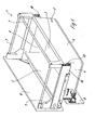
- Figure 1 is a first embodiment of an inventive, overall shown with the reference numeral 1 socket drawer, which is essentially from a drawer base 2 and several to be described Attachments exist.
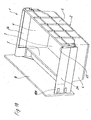
- the drawer base part 2 which in Figure 2 alone in perspective is shown is made in one piece overall and has a bottom 3, two Side walls 4, a front wall 5 and a rear wall 6.
- Add-on parts are the exemplary embodiment according to FIG. 1 Railing struts 7, a drawer panel 8, a base panel 9 and around guide rails 10th
- the drawer base part 2 is provided with molded brackets for Determine the attachments mentioned.
- the drawer base part is in its Corner areas with rear corner posts 11 located in the area of the rear wall 6 and in the area of the front wall, front corner posts 12 provided are integrally formed on the drawer base 2 in the rest.
- the rear and front corner posts 12 serve to receive and hold the Railing struts 7.
- the front corner posts 12 are designed so that in this front corner post 12 still to be described means for adjustable fixing the drawer panel 8 already mentioned can be accommodated.
- drawer base part 2 is in the area of its side walls 4 in the lower, front corner area with screw stands 13 and a guide bar 14 for attaching an also adjustable bracket to be described equipped for the already mentioned base panel 9.
- a drawer base part 2 as in the embodiments according to the figures 3 and 4 shown, is equipped with a rear wall 6, which is clearly above the Side walls 4 also protrudes, rear corner posts 11 can nevertheless be molded on be, so to speak, in the protruding area of the rear wall 6th are integrated.
- a rear wall 6 is shown in FIG Upper edge 6a has an arcuate curved recess, while the The rear wall in the exemplary embodiment according to FIG. 4 is delimited in a straight line at the top is, but in both cases it is clear that the rear corner post 11 is approximately the correspond to the height of the rear wall 6 there and to a certain extent to the rear wall 6 are connected.
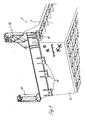
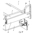
- FIG. 5 makes it clear that a drawer base part 2 in the region of its side walls 4 with molded-on, downwardly open receiving pockets 15 for receiving is equipped with guide rails provided with fastening pins 10a (see Figure 5).
- FIG. 6 also makes it clear that the area of the guide rails 10 after the assembly of the guide rails 10 by clip-on cover profiles 16 is covered.
- This cover profile 16 also covers that area which is required for the adjustable fixing of the base panel 9.
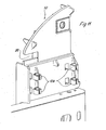
- FIG. 6 also makes it clear that both the rear corner posts 11 and also the front corner posts 12 after the attachment of the railing struts 7 and after the installation of fasteners 17 for fastening a drawer panel 8 can be covered by cover caps 18 or cover plates 19.
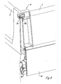
- Figure 7 makes it clear that it is in the front corner posts 12 built-in or integrated fasteners 17 for defining a Drawer panel 8 to fix known, adjustable fastening devices the drawer panel 8 acts. Because these adjustable fasteners are generally known, here is a description of the constructions waived.
- FIG 8 it is shown in detail how the railing struts 7 in the rear corner posts 11 intervene.
- the railing struts 7 are provided with a longitudinal groove 7a into which a longitudinal web 11a of the rear corner posts 11 engages. This makes the railing struts 7 secured against rotation and stabilized overall.
- Figures 9 to 15 show one compared to the previously described embodiments slightly modified embodiments of a base drawer 1.
- the deviations lie essentially in the different design the front corner posts 12.
- the railing struts lying in the area of the side walls 4 7 are inserted in the rear into appropriately designed rear corner posts 11, as already described.
- the side railing struts grip in the front area 7 in a receptacle 20 of the front corner posts 12 and after assembly each front corner post 12 is formed by a correspondingly shaped cover cap 18a covered.
- Also in this embodiment are the front corner posts for receiving fasteners 17 for the Drawer cover 8 equipped.
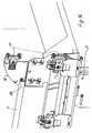
- FIG 14 which is a perspective view of a front corner post 12 with the already mounted fasteners 17 for the drawer panel 8 and with mounted rail strut 7 and with mounted guide rails 10 shows, are already adjustable, known fastening devices 21 for a Base panel 9 mounted.
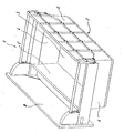
- FIGS. 16 to 17b there is one alternative embodiment of a base drawer 1 according to the invention is shown.
- FIG. 17a and 17b show particularly clearly, both in rear as in the front area in appropriately shaped slide-in holders 23 used, the technically functional the rear or front corner post 11th or 12 correspond.
- the side walls are 4 of the drawer base part 2 increased by profile pieces 24.
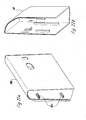
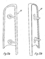
- profile pieces 24 can be clipped onto the side walls 4, but there is also Possibility of these profile pieces 24, one of which is shown in perspective in FIG Is shown, additionally or exclusively by a front, the Drawer panel 8 facing cover cap 18b with molded retaining pins 18c (see Figure 22a) and by a rear adapter 25 (see Figures 23a and 23b) to fix.
- the holding pins 18c engage in molded channels 26 in the assembled state Profile pieces 24.
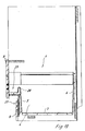
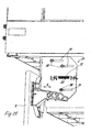
- Figure 19 is a cross section through a Sokkel drawer built into a furniture body 1 shown, which shows particularly clearly that the base drawer 1 - like the plinth drawers described so far - in the area of his Front wall 5 is provided with a lower, recessed area 27.
- This recessed area 27 lies in alignment with a base area several pieces of furniture standing side by side. In this recessed area 27, the base panel 9 is also mounted.
- Figure 19 also shows very clearly that the front wall 5 in the transition area between the recessed area 27 and the drawer panel 8 with a web 28 protruding upwards is provided, whereby an additional loading compartment 29 is created for small parts.
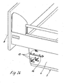
- Figures 24 and 25 also serve to explain the attachment of a fastening device 21 for a base panel 9.
- a drawer base part 2 in the lower, front area its side walls 4 with screw-on brackets 13 and a guide web 14 is provided.
- the screw-on brackets 13 serve to determine the addressed Fastening device 21 by several fastening screws 30.
- This Fastening screws 30 pass through longitudinal slots 31 of the Fastening device 21, so that this overall in the direction of the double arrow A in Figure 25 can be moved and adjusted.
- the guide web 14 passes through a slot 32 in the fastening device 21 and thus ensures precise horizontal guidance of the fastening device 21 when adjusting in the direction of the double arrow A.
- a scale 33 can do that The degree of displacement of the fastening device 21 can be controlled well.
- a fastening device 21 is used, which is an automatic Lifting the base panel 9 when opening a base drawer according to the invention causes.
- Such fasteners 21 are also for seen already known and are therefore not described further here.
- a base drawer 1 according to the present invention offers a high level Stability or stiffness, this being due to the one-piece, made of plastic manufactured drawer base part 2 is reached.
- the usable height of the base drawer 1 can be by railing, profile pieces or the like can be enlarged extremely variably, in addition due to these different attachments also a relatively large variety of Design options for a plinth drawer achieved.
Landscapes
- Drawers Of Furniture (AREA)
- Piezo-Electric Or Mechanical Vibrators, Or Delay Or Filter Circuits (AREA)
- Oscillators With Electromechanical Resonators (AREA)
Abstract
Description
Die vorliegende Erfindung betrifft einen Sockelschubkasten für ein Stellmöbel, mit einem Boden, zwei Seitenwänden, einer Rückwand und einer Vorderwand, welche zur Bodenseite hin stufenartig zurückspringend ausgebildet ist, wobei im oberen, vorstehenden Bereich der Vorderwand eine Schubkastenblende und im unteren, zurückspringenden Bereich der Vorderwand eine Sockelblende und zumindest im Bereich der Seitenwände die nutzbare Höhe des Schubkastens vergrößernde Bauteile vorgesehen sind.The present invention relates to a base drawer for a piece of furniture, with a floor, two side walls, a rear wall and a front wall, which is designed to step back towards the bottom, with the upper, projecting area of the front wall a drawer panel and in the lower, recessed Area of the front wall a base panel and at least in the area components that increase the usable height of the drawer are provided.
Sockelschubkästen der gattungsgemäßen Art sind an sich bekannt. Derartige Sokkelschubkästen werden, wie schon der Name sagt, im Sockelbereich von Stellmöbeln eingesetzt und sind in aller Regel sehr großvolumig ausgebildet und insoweit zur Aufnahme von relativ großen und auch schweren Gegenständen vorgesehen. Dies bedingt natürlich eine entsprechende Stabilität derartiger Sockelschubkästen.Socket drawers of the generic type are known per se. Such drawer drawers are, as the name suggests, in the plinth area of furniture used and are usually very large volume and so far intended to accommodate relatively large and heavy objects. Of course, this requires a corresponding stability of such base drawers.
Die bekannten Sockelschubkästen der gattungsgemäßen Art sind im allgemeinen aus vergleichsweise vielen Einzelteilen zusammengebaut und deshalb auch recht kostenaufwendig.The known base drawers of the generic type are in general assembled from a comparatively large number of individual parts and therefore quite right costly.
Der vorliegenden Erfindung liegt die Aufgabe zugrunde, einen Sockelschubkasten der gattungsgemäßen Art zu schaffen, der vergleichsweise preiswert herstellbar und insbesondere hochbelastbar ist, wobei die Ausbaufähigkeit des Sockelschubkastens auf einfache Art und Weise erreicht sein soll.The present invention has for its object a base drawer to create the generic type that is comparatively inexpensive to manufacture and is particularly heavy-duty, the expandability of the base drawer should be achieved in a simple manner.
Diese Aufgabe wird erfindungsgemäß dadurch gelöst, daß der Sockelschubkasten ein einstückiges, den Boden, die Seitenwände, die Vorderwand und die Rückwand aufweisendes Schubkasten-Basisteil aufweist, an dem die Schubkastenblende, die Sockelblende sowie die nutzbare Höhe vergrößernde Bauteile befestigbar sind, wobei das Schubkasten-Basisteil mit angeformten Halterungen für die besagten Anbauteile versehen ist.This object is achieved in that the base drawer one piece, the bottom, the side walls, the front wall and the rear wall having drawer base part on which the drawer panel, the Base panel and components that increase the usable height can be attached, wherein the drawer base with molded brackets for said Attachments are provided.
Die Verwendung eines einstückig hergestellten Schubkasten-Basisteiles trägt einerseits der Forderung nach hoher Stabilität des Sockelschubkastens Rechnung und andererseits auch der Forderung nach einer preiswerten Herstellmöglichkeit eines entsprechenden Sockelschubkastens. Die Tatsache, daß an das Schubkasten-Basisteil Halterungen angeformt sind, an denen weitere Anbauteile befestigbar sind, ist insofern vorteilhaft, als eine leichte und schnell durchführbare Montage z. B. der Schubkastenblende, der Sockelblende sowie von Bauteilen zur Vergrößerung der nutzbaren Höhe des Sockelschubkastens möglich ist.The use of a one-piece drawer base part carries on the one hand the demand for high stability of the base drawer and on the other hand, the demand for an inexpensive way to manufacture a corresponding base drawer. The fact that the drawer base part Brackets are formed on which other attachments can be attached are advantageous in that an easy and quick installation z. B. the drawer panel, the base panel and components for enlargement the usable height of the base drawer is possible.
Weitere Merkmale der Erfindung sind Gegenstand von Unteransprüchen.Further features of the invention are the subject of dependent claims.
In den beigefügten Zeichnungen sind Ausführungsbeispiele der Erfindung dargestellt, die im folgenden näher beschrieben werden.Exemplary embodiments of the invention are shown in the accompanying drawings, which are described in more detail below.
Es zeigen:
- Figur 1
- eine perspektivische Darstellung eines erfindungsgemäßen Sockelschubkastens mit einer Reling,
Figur 2- eine perspektivische Darstellung eines Schubkasten-Basisteiles des Sokkelschubkastens gemäß Figur 1,
Figur 3- eine der
Figur 2 entsprechende Darstellung eines Schubkasten-Basisteiles nach einem weiteren Ausführungsbeispiel der Erfindung, Figur 4- ein Schubkasten-Basisteil für einen Sockelschubkasten nach einem weiteren Ausführungsbeispiel der Erfindung,
Figur 5- eine perspektivisch dargestellte Unteransicht eines Schubkasten-Basisteiles im Seitenwandbereich,
Figur 6- eine teilperspektivische Abbildung eines Schubkasten-Basisteiles mit einigen am Schubkasten-Basisteil anmontierten Bauteilen, aber noch ohne Schubkastenblende gezeigt,
Figur 7- eine Detaildarstellung einer Befestigungsvorrichtung für eine Schubkastenblende,
Figur 8- eine Detaildarstellung eines rückseitigen Eckbereiches eines erfindungsgmäßen Sockelschubkastens,
Figur 9- eine perspektivische Darstellung eines Sockelschubkastens nach einem weiteren Ausführungsbeispiel der Erfindung im vollständig montierten Zustand,
Figur 10- eine perspektivische Teildarstellung des Sockelschubkastens gemäß
Figur 9 in seinem Seitenwandbereich, Figur 11- eine perspektivisch dargestellte Teilansicht eines vorderen Eckpfostens
eines Sockelschubkastens gemäß
Figur 9, Figur 12- eine perspektivische Ansicht des Eckpfostens gemäß
Figur 11 von der Innenseite des Sockelschubkastens her gesehen und mit einer montierten Reling dargestellt, Figur 13- eine perspektivisch dargestellte Abdeckkappe für einen vorderen Eckpfosten
des Schubkastens gemäß
Figur 9, Figur 14- eine perspektivisch dargestellte Außenansicht eines vorderen Eckbereiches
des Sockelschubkastens gemäß
Figur 9 mit Einrichtungen zur justierbaren Montage einer Schubkastenblende, Figur 15- eine Vorderansicht des stimseitigen Eckbereiches gemäß
Figur 9 vor dem Anbringen einer Schubkastenblende, Figur 16- eine perspektivische Darstellung eines Sockelschubkastens nach einem weiteren Ausführungsbeispiel der Erfindung,
- Figuren 17a,17b
- perspektivische Teilansichten des hinteren sowie des vorderen Eckbereiches
des Sockelschubkastens gemäß
Figur 16, Figur 18- eine perspektivische Darstellung eines Sockelschubkastens nach einem weiteren Ausführungsbeispiel der Erfindung,
Figur 19- einen Längsschnitt durch einen Sockelschubkasten gemäß
Figur 18, Figur 20- einen Schnitt durch den Seitenwandbereich eines Sockelschubkastens
gemäß den
Figuren 18 und 19, Figur 21- eine perspektivische Darstellung eines Profilstückes zur Vergrößerung
der nutzbaren Höhe des Sockelschubkastens nach den
Figuren 18 und 19, - Figuren 22a, 22b
- zwei perspektivische Darstellungen einer vorderen Abdeckkappe eines
Sockelschubkastens gemäß
Figur 18 zur Halterung eines Profilstückes gemäßFigur 21, - Figuren 23a, 23b
- perspektivische Darstellungen eines im rückwärtigen Seitenwandbereich
anbringbaren Adapters zur dortigen Halterung eines Profilstückes gemäß
Figur 21, Figur 24- eine perspektivische Teildarstellung eines vorderen Eckbereiches eines Sockelschubkastens mit angeformten Mitteln zur Befestigung einer Vorrichtung zur Sockelblenden-Befestigung,
Figur 25- eine perspektivische Teildarstellung des vorderen Eckbereiches eines Sockelschubkastens mit justierbar montierter Sockelblende.
- Figure 1
- 2 shows a perspective illustration of a base drawer according to the invention with a railing,
- Figure 2
- 2 shows a perspective illustration of a drawer base part of the socket drawer according to FIG. 1,
- Figure 3
- 2 shows a representation of a drawer base part according to a further exemplary embodiment of the invention,
- Figure 4
- a drawer base part for a base drawer according to a further embodiment of the invention,
- Figure 5
- 2 shows a perspective bottom view of a drawer base part in the side wall area,
- Figure 6
- a partial perspective illustration of a drawer base part with some components mounted on the drawer base part, but still without a drawer cover,
- Figure 7
- a detailed view of a fastening device for a drawer panel,
- Figure 8
- 2 shows a detailed representation of a rear corner area of a base drawer according to the invention,
- Figure 9
- 2 shows a perspective view of a base drawer according to a further exemplary embodiment of the invention in the fully assembled state,
- Figure 10
- 9 shows a perspective partial representation of the base drawer according to FIG. 9 in its side wall area,
- Figure 11
- 3 shows a perspective view of a front corner post of a base drawer according to FIG. 9,
- Figure 12
- 11 shows a perspective view of the corner post according to FIG. 11 seen from the inside of the base drawer and shown with a mounted railing,
- Figure 13
- 9 shows a cover cap shown in perspective for a front corner post of the drawer according to FIG. 9,
- Figure 14
- 9 shows a perspective external view of a front corner area of the base drawer according to FIG. 9 with devices for the adjustable assembly of a drawer cover
- Figure 15
- 9 shows a front view of the front corner area according to FIG. 9 before attaching a drawer cover,
- Figure 16
- 2 shows a perspective illustration of a base drawer according to a further exemplary embodiment of the invention,
- Figures 17a, 17b
- perspective partial views of the rear and the front corner area of the base drawer according to FIG. 16,
- Figure 18
- 2 shows a perspective illustration of a base drawer according to a further exemplary embodiment of the invention,
- Figure 19
- 6 shows a longitudinal section through a base drawer according to FIG. 18,
- Figure 20
- 5 shows a section through the side wall region of a base drawer according to FIGS. 18 and 19,
- Figure 21
- 3 shows a perspective illustration of a profile piece for increasing the usable height of the base drawer according to FIGS. 18 and 19,
- Figures 22a, 22b
- two perspective representations of a front cover cap of a base drawer according to FIG. 18 for holding a profile piece according to FIG. 21,
- Figures 23a, 23b
- perspective views of an adapter which can be attached in the rear side wall area for holding a profile piece there according to FIG. 21,
- Figure 24
- 2 shows a perspective partial illustration of a front corner region of a base drawer with molded-on means for attaching a device for attaching base cover panels,
- Figure 25
- a partial perspective view of the front corner area of a plinth drawer with an adjustable plinth panel.
In Figur 1 ist ein erstes Ausführungsbeispiel eines erfindungsgemäßen, insgesamt
mit dem Bezugszeichen 1 bezeichneten Sockelschubkastens gezeigt, der im wesentlichen
aus einem Schubkasten-Basisteil 2 und mehreren, noch zu beschreibenden
Anbauteilen besteht.In Figure 1 is a first embodiment of an inventive, overall
shown with the reference numeral 1 socket drawer, which is essentially
from a
Das Schubkasten-Basisteil 2, welches in Figur 2 in perspektivischer Darstellung alleine
gezeigt ist, ist insgesamt einstückig hergestellt und weist einen Boden 3, zwei
Seitenwände 4, eine Vorderwand 5 und eine Rückwand 6 auf. Bei den schon erwähnten
Anbauteilen handelt es sich beim Ausführungsbeispiel gemäß Figur 1 um
Relingstreben 7, eine Schubkastenblende 8, eine Sockelblende 9 und um Führungsschienen
10.The
Das Schubkasten-Basisteil 2 ist mit angeformten Halterungen versehen, die zur
Festlegung der genannten Anbauteile dienen. The
So ist, was Figur 2 besonders deutlich zeigt, das Schubkasten-Basisteil in seinen
Eckbereichen mit im Bereich der Rückwand 6 liegenden, hinteren Eckpfosten 11
sowie im Bereich der Vorderwand liegenden, vorderen Eckpfosten 12 versehen, die
einstückig an das Schubkasten-Basisteil 2 im übrigen angeformt sind.Thus, what is particularly clearly shown in FIG. 2, the drawer base part is in its
Corner areas with rear corner posts 11 located in the area of the
Die hinteren und vorderen Eckpfosten 12 dienen zur Aufnahme und Halterung der
Relingstreben 7. Zusätzlich sind die vorderen Eckpfosten 12 so ausgebildet, daß in
diesen vorderen Eckpfosten 12 noch zu beschreibende Mittel zur justierbaren Festlegung
der schon erwähnten Schubkastenblende 8 untergebracht werden können.The rear and front corner posts 12 serve to receive and hold the
Railing struts 7. In addition, the front corner posts 12 are designed so that in
this
Weiterhin ist das Schubkasten-Basisteil 2 im Bereich seiner Seitenwände 4 im unteren,
vorderen Eckbereich mit Anschraubböcken 13 und einem Führungssteg 14
zur Anbringung einer ebenfalls noch zu beschreibenden, ebenfalls justierbaren Halterung
für die schon erwähnte Sockelblende 9 ausgestattet.Furthermore, the
Falls ein Schubkasten-Basisteil 2, wie bei den Ausführungsbeispielen nach den Figuren
3 und 4 gezeigt, mit einer Rückwand 6 ausgestattet ist, die deutlich über die
Seitenwände 4 hinaus vorsteht, können gleichwohl hintere Eckpfosten 11 angeformt
sein, die dann gewissermaßen in den überstehenden Bereich der Rückwand 6
integriert sind. Dabei ist in Figur 3 eine Rückwand 6 gezeigt, die im Bereich ihrer
Oberkante 6a eine bogenförmig geschwungene Ausnehmung aufweist, während die
Rückwand beim Ausführungsbeispiel gemäß Figur 4 oberseitig geradlinig begrenzt
ist, in beiden Fällen ist aber deutlich, daß die hinteren Eckpfosten 11 in etwa der
dortigen Höhe der Rückwand 6 entsprechen und gewissermaßen an die Rückwand
6 angebunden sind.If a
Figur 5 macht deutlich, daß ein Schubkasten-Basisteil 2 im Bereich seiner Seitenwände
4 mit angeformten, nach unten offenen Aufnahmetaschen 15 zur Aufnahme
von mit Befestigungszapfen 10a versehenen Führungsschienen ausgestattet ist (sh.
Figur 5).Figure 5 makes it clear that a
Figur 6 macht hierzu ergänzend deutlich, daß der Bereich der Führungsschienen 10
nach der Montage der Führungsschienen 10 durch aufclipsbare Abdeckprofile 16
abgedeckt ist. Durch diese Abdeckprofile 16 ist auch derjenige Bereich abdeckbar,
der zur justierbaren Festlegung der Sockelblende 9 benötigt wird.FIG. 6 also makes it clear that the area of the guide rails 10
after the assembly of the guide rails 10 by clip-on
Figur 6 macht darüber hinaus deutlich, daß sowohl die hinteren Eckpfosten 11 wie
auch die vorderen Eckpfosten 12 nach der Anbringung der Relingstreben 7 sowie
nach dem Einbau von Befestigungsmitteln 17 zur Befestigung einer Schubkastenblende
8 durch Abdeckkappen 18 oder Abdeckplatten 19 abdeckbar sind.Figure 6 also makes it clear that both the rear corner posts 11 and
also the front corner posts 12 after the attachment of the railing struts 7 and
after the installation of
Ergänzend macht Figur 7 deutlich, daß es sich bei den in die vorderen Eckpfosten
12 eingebauten oder integrierten Befestigungsmitteln 17 zur Festlegung einer
Schubkastenblende 8 um bekannte, justierbare Befestigungseinrichtungen zur Festlegung
der Schubkastenblende 8 handelt. Da diese justierbaren Befestigungseinrichtungen
grundsätzlich bekannt sind, wird hier auf eine Beschreibung der Konstruktionen
verzichtet.In addition, Figure 7 makes it clear that it is in the front corner posts
12 built-in or
Wesentlich ist lediglich, daß hier entsprechende, eine Justierung einer Schubkastenblende
8 ermöglichende Konstruktionen, die dem Fachmann bekannt sind,
Verwendung finden können.The only essential thing is that here an appropriate adjustment of a
In Figur 8 ist detailliert gezeigt, wie die Relingstreben 7 in die hinteren Eckpfosten
11 eingreifen. Die Relingstreben 7 sind mit einer Längsnut 7a versehen, in welche
ein Längssteg 11a der hinteren Eckpfosten 11 eingreift. Dadurch sind die Relingstreben
7 gegen Verdrehung gesichert und insgesamt stabilisiert.In Figure 8 it is shown in detail how the railing struts 7 in the rear corner posts
11 intervene. The railing struts 7 are provided with a
Die Figuren 9 bis 15 zeigen eine gegenüber den bisher beschriebenen Ausführungsbeispielen
leicht abgewandelte Ausführungsformen eines Sockelschubkastens
1. Die Abweichungen liegen hier im wesentlichen in der abweichenden Gestaltung
der vorderen Eckpfosten 12. Die im Bereich der Seitenwände 4 liegenden Relingstreben
7 sind rückwärtig in entsprechend gestaltete hintere Eckpfosten 11 eingeschoben,
wie schon beschrieben. Im vorderen Bereich greifen die seitlichen Relingstreben
7 in eine Aufnahme 20 der vorderen Eckpfosten 12 und nach der Montage
wird jeder vordere Eckpfosten 12 durch eine entsprechend geformte Abdeckkappe
18a überdeckt. Dabei wird die jeweilige Abdeckkappe 18a mit den angeformten
Befestigungsmitteln 18d auf einen vorderen Eckpfosten 12 aufgeschnäppt,
der entsprechende Haltemittel 12b aufweist. Auch in diesen Ausführungsbeispiel
sind die vorderen Eckpfosten zur Aufnahme von Befestigungsmitteln 17 für die
Schubkastenblende 8 ausgestattet.Figures 9 to 15 show one compared to the previously described embodiments
slightly modified embodiments of a base drawer
1. The deviations lie essentially in the different design
the front corner posts 12. The railing struts lying in the area of the
Wie aus Figur 14, welche einen perspektivischen Blick auf einen vorderen Eckpfosten
12 mit den schon montierten Befestigungsmitteln 17 für die Schubkastenblende
8 und mit montierter Relingstrebe 7 sowie mit montierten Führungsschienen 10
zeigt, sind auch schon justierbare, bekannte Befestigungseinrichtungen 21 für eine
Sockelblende 9 montiert.As in Figure 14, which is a perspective view of a front corner post
12 with the already mounted
Beim Ausführungsbeispiel der Erfindung gemäß den Figuren 16 bis 17b ist eine alternative Ausführungsform eines erfindungsgemäßen Sockelschubkastens 1 gezeigt.In the exemplary embodiment of the invention according to FIGS. 16 to 17b there is one alternative embodiment of a base drawer 1 according to the invention is shown.
Hier sind die seitlichen Relingstreben durch plattenförmige Einschubstücke 22 beispielsweise
aus Holz oder Glas ersetzt. Dabei sind diese plattenförmigen Einschubstücke,
wie die Figuren 17a und 17b besonders deutlich zeigen, sowohl im
rückwärtigen wie im vorderen Bereich in entsprechend geformte Einschubhalter 23
eingesetzt, die technisch funktionell dem hinteren bzw. vorderen Eckpfosten 11
bzw. 12 entsprechen.Here are the side rail struts by plate-shaped
Beim Ausführungsbeispiel der Erfindung nach den Figuren 18 bis 23b sind die Seitenwände
4 des Schubkasten-Basisteiles 2 durch Profilstücke 24 erhöht. Diese Profilstücke
24 können auf die Seitenwände 4 aufgeclipst sein, es besteht aber auch die
Möglichkeit, diese Profilstücke 24, von denen eines in Figur 21 in perspektivischer
Darstellung gezeigt ist, zusätzlich oder ausschließlich durch eine vordere, der
Schubkastenblende 8 zugewandt liegende Abdeckkappe 18b mit angeformten Haltezapfen
18c (siehe Figur 22a) und durch einen hinteren Adapter 25 (siehe Figuren
23a und 23b) zu fixieren.In the exemplary embodiment of the invention according to FIGS. 18 to 23b, the side walls are
4 of the
Die Haltezapfen 18c greifen im montierten Zustand in angeformte Kanäle 26 der
Profilstücke 24. The holding pins 18c engage in molded
In Figur 19 ist ein Querschnitt durch einen in einen Möbelkorpus eingebauten Sokkelschubkasten
1 gezeigt, der besonders anschaulich zeigt, daß der Sockelschubkasten
1 - wie auch die bisher beschriebenen Sockelschubkästen - im Bereich seiner
Vorderwand 5 mit einem unteren, zurückspringenden Bereich 27 versehen ist. Dieser
zurückspringende Bereich 27 liegt in einer Flucht mit einem Sockelbereich
mehrerer, nebeneinanderstehender Möbel. In diesem zurückspringenden Bereich
27 ist auch die Sockelblende 9 montiert.In Figure 19 is a cross section through a Sokkel drawer built into a furniture body
1 shown, which shows particularly clearly that the base drawer
1 - like the plinth drawers described so far - in the area of his
Figur 19 zeigt außerdem sehr deutlich, daß die Vorderwand 5 im Übergangsbereich
zwischen dem zurückspringenden Bereich 27 und der Schubkastenblende 8 mit einem
nach oben vorstehenden Steg 28 versehen ist, wodurch ein zusätzliches Beschickungsfach
29 für Kleinteile geschaffen ist.Figure 19 also shows very clearly that the
Die Figuren 24 und 25 dienen noch zur Erläuterung der Anbringung einer Befestigungseinrichtung
21 für eine Sockelblende 9.Figures 24 and 25 also serve to explain the attachment of a
Es wurde schon erwähnt, daß ein Schubkasten-Basisteil 2 im unteren, vorderen Bereich
seiner Seitenwände 4 mit Anschraubböcken 13 und einem Führungssteg 14
versehen ist. Die Anschraubböcke 13 dienen dabei zur Festlegung der angesprochenen
Befestigungseinrichtung 21 durch mehrere Befestigungsschrauben 30. Diese
Befestigungsschrauben 30 durchtreten Längsschlitze 31 der
Befestigungseinrichtung 21, so daß diese insgesamt in Richtung des Doppelpfeiles
A in Figur 25 verschoben und justiert werden kann.It has already been mentioned that a
Der Führungssteg 14 durchtritt einen Schlitz 32 der Befestigungseinrichtung 21
und sorgt so für eine präzise Horizontalführung der Befestigungseinrichtung 21
beim Justieren in Richtung des Doppelpfeiles A. Durch eine Skala 33 kann das
Maß der Verschiebung der Befestigungseinrichtung 21 gut kontrolliert werden.The
Ganz allgemein wird eine Befestigungseinrichtung 21 verwendet, die ein selbsttätiges
Anheben der Sockelblende 9 beim Öffnen eines erfindungsgemäßen Sockelschubkastens
bewirkt. Derartige Befestigungseinrichtungen 21 sind ebenfalls für
sich gesehen bereits bekannt und sind an dieser Stelle deshalb nicht weiter beschrieben. In general, a
Insgesamt bietet ein Sockelschubkasten 1 gemäß vorliegender Erfindung eine hohe
Stabilität bzw. Steifigkeit, wobei diese durch das einstückig gefertigte, aus Kunststoff
hergestellte Schubkasten-Basisteil 2 erreicht wird.Overall, a base drawer 1 according to the present invention offers a high level
Stability or stiffness, this being due to the one-piece, made of plastic
manufactured
Die nutzbare Höhe des Sockelschubkastens 1 kann durch Relingstreben, Profilstücke oder dergleichen äußerst variabel vergrößert werden, außerdem wird durch diese unterschiedlichen Anbauteile auch eine relativ große Vielfalt von Gestaltungsmöglichkeiten für einen Sockelschubkasten erreicht.The usable height of the base drawer 1 can be by railing, profile pieces or the like can be enlarged extremely variably, in addition due to these different attachments also a relatively large variety of Design options for a plinth drawer achieved.
Claims (12)
Applications Claiming Priority (2)
| Application Number | Priority Date | Filing Date | Title |
|---|---|---|---|
| DE20306053U DE20306053U1 (en) | 2003-04-16 | 2003-04-16 | Plinth drawer |
| DE20306053U | 2003-04-16 |
Publications (2)
| Publication Number | Publication Date |
|---|---|
| EP1470768A1 true EP1470768A1 (en) | 2004-10-27 |
| EP1470768B1 EP1470768B1 (en) | 2006-05-03 |
Family
ID=7981518
Family Applications (1)
| Application Number | Title | Priority Date | Filing Date |
|---|---|---|---|
| EP04400008A Expired - Lifetime EP1470768B1 (en) | 2003-04-16 | 2004-03-04 | Cabinet base drawer |
Country Status (4)
| Country | Link |
|---|---|
| EP (1) | EP1470768B1 (en) |
| AT (1) | ATE324817T1 (en) |
| DE (2) | DE20306053U1 (en) |
| ES (1) | ES2262108T3 (en) |
Cited By (3)
| Publication number | Priority date | Publication date | Assignee | Title |
|---|---|---|---|---|
| ES2304287A1 (en) * | 2006-03-28 | 2008-10-01 | Florestan Guerrero Yritia | Medical classifier drawer and its manufacturing procedure (Machine-translation by Google Translate, not legally binding) |
| ES2316204A1 (en) * | 2005-08-04 | 2009-04-01 | Miguel Angel Rioja Calvo | Device for constitution and stacking of furniture drawers. (Machine-translation by Google Translate, not legally binding) |
| CN102058256A (en) * | 2010-10-27 | 2011-05-18 | 世塑有限公司 | Heightened drawer side plate structure |
Families Citing this family (3)
| Publication number | Priority date | Publication date | Assignee | Title |
|---|---|---|---|---|
| DE202008008540U1 (en) * | 2008-06-30 | 2009-11-19 | Paul Hettich Gmbh & Co. Kg | wall element |
| DE202008009396U1 (en) * | 2008-07-14 | 2009-11-26 | Paul Hettich Gmbh & Co. Kg | drawer |
| KR102003118B1 (en) * | 2017-06-30 | 2019-07-24 | 명진실업 주식회사 | Drawable carrier assembly for kitchen furniture |
Citations (3)
| Publication number | Priority date | Publication date | Assignee | Title |
|---|---|---|---|---|
| EP0387494A2 (en) * | 1989-03-16 | 1990-09-19 | Ninkaplast GmbH | Base sliding drawer |
| DE20120585U1 (en) * | 2001-12-20 | 2003-04-30 | Ninkaplast GmbH, 32108 Bad Salzuflen | Plinth drawer |
| EP1319352A1 (en) * | 2001-12-14 | 2003-06-18 | Paul Hettich Gmbh & Co. | Lowermost drawer for a furniture |
-
2003
- 2003-04-16 DE DE20306053U patent/DE20306053U1/en not_active Expired - Lifetime
-
2004
- 2004-03-04 ES ES04400008T patent/ES2262108T3/en not_active Expired - Lifetime
- 2004-03-04 EP EP04400008A patent/EP1470768B1/en not_active Expired - Lifetime
- 2004-03-04 DE DE502004000495T patent/DE502004000495D1/en not_active Expired - Lifetime
- 2004-03-04 AT AT04400008T patent/ATE324817T1/en active
Patent Citations (3)
| Publication number | Priority date | Publication date | Assignee | Title |
|---|---|---|---|---|
| EP0387494A2 (en) * | 1989-03-16 | 1990-09-19 | Ninkaplast GmbH | Base sliding drawer |
| EP1319352A1 (en) * | 2001-12-14 | 2003-06-18 | Paul Hettich Gmbh & Co. | Lowermost drawer for a furniture |
| DE20120585U1 (en) * | 2001-12-20 | 2003-04-30 | Ninkaplast GmbH, 32108 Bad Salzuflen | Plinth drawer |
Cited By (4)
| Publication number | Priority date | Publication date | Assignee | Title |
|---|---|---|---|---|
| ES2316204A1 (en) * | 2005-08-04 | 2009-04-01 | Miguel Angel Rioja Calvo | Device for constitution and stacking of furniture drawers. (Machine-translation by Google Translate, not legally binding) |
| ES2304287A1 (en) * | 2006-03-28 | 2008-10-01 | Florestan Guerrero Yritia | Medical classifier drawer and its manufacturing procedure (Machine-translation by Google Translate, not legally binding) |
| CN102058256A (en) * | 2010-10-27 | 2011-05-18 | 世塑有限公司 | Heightened drawer side plate structure |
| CN102058256B (en) * | 2010-10-27 | 2013-03-06 | 东莞世巨五金塑胶制品有限公司 | Heightened drawer side plate structure |
Also Published As
| Publication number | Publication date |
|---|---|
| DE502004000495D1 (en) | 2006-06-08 |
| ES2262108T3 (en) | 2006-11-16 |
| DE20306053U1 (en) | 2003-06-26 |
| EP1470768B1 (en) | 2006-05-03 |
| ATE324817T1 (en) | 2006-06-15 |
Similar Documents
| Publication | Publication Date | Title |
|---|---|---|
| DE29516695U1 (en) | System for creating office and / or work environments | |
| DE3832701A1 (en) | FASTENING ARRANGEMENT FOR THE GUIDE RAIL OF A EXTENSION GUIDE | |
| DE202005006862U1 (en) | Bottomless drawer | |
| DE202011110018U1 (en) | drawer system | |
| EP0664982A2 (en) | Fitting | |
| WO2018166839A1 (en) | Panel structure for a drawer | |
| EP3595490B1 (en) | Panel structure for a drawer | |
| EP1470768A1 (en) | Cabinet base drawer | |
| AT401851B (en) | FITTING | |
| EP2844108B1 (en) | Holding device for a supporting element of a cabinet, such as a refrigerator, a freezer or a cabinet for storing wine | |
| EP2801291A1 (en) | Furniture fitting to form a pull-out waste collection device | |
| EP3369341B1 (en) | Wall element for a frame of a drawer | |
| DE4437228C2 (en) | Office table with a coupling mechanism for add-on elements | |
| DE4012650C2 (en) | BRACKET FITTING FOR DRAWER EXTENSION GUIDES | |
| EP1676500B1 (en) | Lowermost drawer for a piece of furniture | |
| AT410629B (en) | TELESCOPE CABINET EXCERPT | |
| EP1427311B1 (en) | Drawer | |
| DE8330541U1 (en) | DRAWER | |
| DE9410504U1 (en) | drawer | |
| DE9422457U1 (en) | Fitting for fastening a rear wall of a drawer | |
| DE102012109589B4 (en) | furniture | |
| CH665539A5 (en) | Support for hanging guides for drawers - fits in side rails by slits without special tools | |
| EP4385364A1 (en) | Retaining element for an extendable cabinet frame for a pull-out tall cabinet | |
| EP3783287A1 (en) | Storage base with a specific central bridge for separate panel parts | |
| DE202018103146U1 (en) | Fitting for attaching a hanging furniture to a wall and hanging furniture |
Legal Events
| Date | Code | Title | Description |
|---|---|---|---|
| PUAI | Public reference made under article 153(3) epc to a published international application that has entered the european phase |
Free format text: ORIGINAL CODE: 0009012 |
|
| AK | Designated contracting states |
Kind code of ref document: A1 Designated state(s): AT BE BG CH CY CZ DE DK EE ES FI FR GB GR HU IE IT LI LU MC NL PL PT RO SE SI SK TR |
|
| AX | Request for extension of the european patent |
Extension state: AL HR LT LV MK |
|
| 17P | Request for examination filed |
Effective date: 20050405 |
|
| 17Q | First examination report despatched |
Effective date: 20050506 |
|
| AKX | Designation fees paid |
Designated state(s): AT BE BG CH CY CZ DE DK EE ES FI FR GB GR HU IE IT LI LU MC NL PL PT RO SE SI SK TR |
|
| GRAP | Despatch of communication of intention to grant a patent |
Free format text: ORIGINAL CODE: EPIDOSNIGR1 |
|
| GRAS | Grant fee paid |
Free format text: ORIGINAL CODE: EPIDOSNIGR3 |
|
| GRAA | (expected) grant |
Free format text: ORIGINAL CODE: 0009210 |
|
| AK | Designated contracting states |
Kind code of ref document: B1 Designated state(s): AT BE BG CH CY CZ DE DK EE ES FI FR GB GR HU IE IT LI LU MC NL PL PT RO SE SI SK TR |
|
| PG25 | Lapsed in a contracting state [announced via postgrant information from national office to epo] |
Ref country code: SK Free format text: LAPSE BECAUSE OF FAILURE TO SUBMIT A TRANSLATION OF THE DESCRIPTION OR TO PAY THE FEE WITHIN THE PRESCRIBED TIME-LIMIT Effective date: 20060503 Ref country code: IE Free format text: LAPSE BECAUSE OF FAILURE TO SUBMIT A TRANSLATION OF THE DESCRIPTION OR TO PAY THE FEE WITHIN THE PRESCRIBED TIME-LIMIT Effective date: 20060503 Ref country code: IT Free format text: LAPSE BECAUSE OF FAILURE TO SUBMIT A TRANSLATION OF THE DESCRIPTION OR TO PAY THE FEE WITHIN THE PRESCRIBED TIME-LIMIT;WARNING: LAPSES OF ITALIAN PATENTS WITH EFFECTIVE DATE BEFORE 2007 MAY HAVE OCCURRED AT ANY TIME BEFORE 2007. THE CORRECT EFFECTIVE DATE MAY BE DIFFERENT FROM THE ONE RECORDED. Effective date: 20060503 Ref country code: SI Free format text: LAPSE BECAUSE OF FAILURE TO SUBMIT A TRANSLATION OF THE DESCRIPTION OR TO PAY THE FEE WITHIN THE PRESCRIBED TIME-LIMIT Effective date: 20060503 Ref country code: PL Free format text: LAPSE BECAUSE OF FAILURE TO SUBMIT A TRANSLATION OF THE DESCRIPTION OR TO PAY THE FEE WITHIN THE PRESCRIBED TIME-LIMIT Effective date: 20060503 Ref country code: CZ Free format text: LAPSE BECAUSE OF FAILURE TO SUBMIT A TRANSLATION OF THE DESCRIPTION OR TO PAY THE FEE WITHIN THE PRESCRIBED TIME-LIMIT Effective date: 20060503 Ref country code: RO Free format text: LAPSE BECAUSE OF FAILURE TO SUBMIT A TRANSLATION OF THE DESCRIPTION OR TO PAY THE FEE WITHIN THE PRESCRIBED TIME-LIMIT Effective date: 20060503 Ref country code: FI Free format text: LAPSE BECAUSE OF FAILURE TO SUBMIT A TRANSLATION OF THE DESCRIPTION OR TO PAY THE FEE WITHIN THE PRESCRIBED TIME-LIMIT Effective date: 20060503 |
|
| REG | Reference to a national code |
Ref country code: GB Ref legal event code: FG4D Free format text: NOT ENGLISH |
|
| REG | Reference to a national code |
Ref country code: CH Ref legal event code: EP |
|
| REF | Corresponds to: |
Ref document number: 502004000495 Country of ref document: DE Date of ref document: 20060608 Kind code of ref document: P |
|
| REG | Reference to a national code |
Ref country code: IE Ref legal event code: FG4D Free format text: LANGUAGE OF EP DOCUMENT: GERMAN |
|
| PG25 | Lapsed in a contracting state [announced via postgrant information from national office to epo] |
Ref country code: SE Free format text: LAPSE BECAUSE OF FAILURE TO SUBMIT A TRANSLATION OF THE DESCRIPTION OR TO PAY THE FEE WITHIN THE PRESCRIBED TIME-LIMIT Effective date: 20060803 Ref country code: DK Free format text: LAPSE BECAUSE OF FAILURE TO SUBMIT A TRANSLATION OF THE DESCRIPTION OR TO PAY THE FEE WITHIN THE PRESCRIBED TIME-LIMIT Effective date: 20060803 |
|
| GBT | Gb: translation of ep patent filed (gb section 77(6)(a)/1977) |
Effective date: 20060816 |
|
| PG25 | Lapsed in a contracting state [announced via postgrant information from national office to epo] |
Ref country code: PT Free format text: LAPSE BECAUSE OF FAILURE TO SUBMIT A TRANSLATION OF THE DESCRIPTION OR TO PAY THE FEE WITHIN THE PRESCRIBED TIME-LIMIT Effective date: 20061003 |
|
| REG | Reference to a national code |
Ref country code: ES Ref legal event code: FG2A Ref document number: 2262108 Country of ref document: ES Kind code of ref document: T3 |
|
| ET | Fr: translation filed | ||
| REG | Reference to a national code |
Ref country code: IE Ref legal event code: FD4D |
|
| PLBE | No opposition filed within time limit |
Free format text: ORIGINAL CODE: 0009261 |
|
| STAA | Information on the status of an ep patent application or granted ep patent |
Free format text: STATUS: NO OPPOSITION FILED WITHIN TIME LIMIT |
|
| 26N | No opposition filed |
Effective date: 20070206 |
|
| BERE | Be: lapsed |
Owner name: PAUL HETTICH G.M.B.H. & CO. KG Effective date: 20070331 |
|
| PG25 | Lapsed in a contracting state [announced via postgrant information from national office to epo] |
Ref country code: BE Free format text: LAPSE BECAUSE OF NON-PAYMENT OF DUE FEES Effective date: 20070331 |
|
| PG25 | Lapsed in a contracting state [announced via postgrant information from national office to epo] |
Ref country code: MC Free format text: LAPSE BECAUSE OF NON-PAYMENT OF DUE FEES Effective date: 20070331 |
|
| PG25 | Lapsed in a contracting state [announced via postgrant information from national office to epo] |
Ref country code: GR Free format text: LAPSE BECAUSE OF FAILURE TO SUBMIT A TRANSLATION OF THE DESCRIPTION OR TO PAY THE FEE WITHIN THE PRESCRIBED TIME-LIMIT Effective date: 20060804 |
|
| PG25 | Lapsed in a contracting state [announced via postgrant information from national office to epo] |
Ref country code: BG Free format text: LAPSE BECAUSE OF FAILURE TO SUBMIT A TRANSLATION OF THE DESCRIPTION OR TO PAY THE FEE WITHIN THE PRESCRIBED TIME-LIMIT Effective date: 20060803 |
|
| PG25 | Lapsed in a contracting state [announced via postgrant information from national office to epo] |
Ref country code: EE Free format text: LAPSE BECAUSE OF FAILURE TO SUBMIT A TRANSLATION OF THE DESCRIPTION OR TO PAY THE FEE WITHIN THE PRESCRIBED TIME-LIMIT Effective date: 20060503 |
|
| PGRI | Patent reinstated in contracting state [announced from national office to epo] |
Ref country code: IT Effective date: 20080601 |
|
| REG | Reference to a national code |
Ref country code: CH Ref legal event code: PL |
|
| PG25 | Lapsed in a contracting state [announced via postgrant information from national office to epo] |
Ref country code: CH Free format text: LAPSE BECAUSE OF NON-PAYMENT OF DUE FEES Effective date: 20080331 Ref country code: LI Free format text: LAPSE BECAUSE OF NON-PAYMENT OF DUE FEES Effective date: 20080331 |
|
| PG25 | Lapsed in a contracting state [announced via postgrant information from national office to epo] |
Ref country code: CY Free format text: LAPSE BECAUSE OF FAILURE TO SUBMIT A TRANSLATION OF THE DESCRIPTION OR TO PAY THE FEE WITHIN THE PRESCRIBED TIME-LIMIT Effective date: 20060503 Ref country code: LU Free format text: LAPSE BECAUSE OF NON-PAYMENT OF DUE FEES Effective date: 20070304 |
|
| PG25 | Lapsed in a contracting state [announced via postgrant information from national office to epo] |
Ref country code: HU Free format text: LAPSE BECAUSE OF FAILURE TO SUBMIT A TRANSLATION OF THE DESCRIPTION OR TO PAY THE FEE WITHIN THE PRESCRIBED TIME-LIMIT Effective date: 20061104 Ref country code: TR Free format text: LAPSE BECAUSE OF FAILURE TO SUBMIT A TRANSLATION OF THE DESCRIPTION OR TO PAY THE FEE WITHIN THE PRESCRIBED TIME-LIMIT Effective date: 20060503 |
|
| PGFP | Annual fee paid to national office [announced via postgrant information from national office to epo] |
Ref country code: IT Payment date: 20120327 Year of fee payment: 9 |
|
| PGFP | Annual fee paid to national office [announced via postgrant information from national office to epo] |
Ref country code: ES Payment date: 20130320 Year of fee payment: 10 Ref country code: FR Payment date: 20130329 Year of fee payment: 10 Ref country code: GB Payment date: 20130318 Year of fee payment: 10 |
|
| PGFP | Annual fee paid to national office [announced via postgrant information from national office to epo] |
Ref country code: NL Payment date: 20130318 Year of fee payment: 10 |
|
| REG | Reference to a national code |
Ref country code: NL Ref legal event code: V1 Effective date: 20141001 |
|
| GBPC | Gb: european patent ceased through non-payment of renewal fee |
Effective date: 20140304 |
|
| REG | Reference to a national code |
Ref country code: FR Ref legal event code: ST Effective date: 20141128 |
|
| PG25 | Lapsed in a contracting state [announced via postgrant information from national office to epo] |
Ref country code: FR Free format text: LAPSE BECAUSE OF NON-PAYMENT OF DUE FEES Effective date: 20140331 Ref country code: GB Free format text: LAPSE BECAUSE OF NON-PAYMENT OF DUE FEES Effective date: 20140304 |
|
| PG25 | Lapsed in a contracting state [announced via postgrant information from national office to epo] |
Ref country code: NL Free format text: LAPSE BECAUSE OF NON-PAYMENT OF DUE FEES Effective date: 20141001 |
|
| PG25 | Lapsed in a contracting state [announced via postgrant information from national office to epo] |
Ref country code: IT Free format text: LAPSE BECAUSE OF FAILURE TO SUBMIT A TRANSLATION OF THE DESCRIPTION OR TO PAY THE FEE WITHIN THE PRESCRIBED TIME-LIMIT Effective date: 20140304 |
|
| REG | Reference to a national code |
Ref country code: ES Ref legal event code: FD2A Effective date: 20150424 |
|
| PG25 | Lapsed in a contracting state [announced via postgrant information from national office to epo] |
Ref country code: ES Free format text: LAPSE BECAUSE OF NON-PAYMENT OF DUE FEES Effective date: 20140305 |
|
| PGFP | Annual fee paid to national office [announced via postgrant information from national office to epo] |
Ref country code: DE Payment date: 20160322 Year of fee payment: 13 |
|
| PGFP | Annual fee paid to national office [announced via postgrant information from national office to epo] |
Ref country code: AT Payment date: 20160318 Year of fee payment: 13 |
|
| REG | Reference to a national code |
Ref country code: DE Ref legal event code: R119 Ref document number: 502004000495 Country of ref document: DE |
|
| REG | Reference to a national code |
Ref country code: AT Ref legal event code: MM01 Ref document number: 324817 Country of ref document: AT Kind code of ref document: T Effective date: 20170304 |
|
| PG25 | Lapsed in a contracting state [announced via postgrant information from national office to epo] |
Ref country code: AT Free format text: LAPSE BECAUSE OF NON-PAYMENT OF DUE FEES Effective date: 20170304 Ref country code: DE Free format text: LAPSE BECAUSE OF NON-PAYMENT OF DUE FEES Effective date: 20171003 |