EP1676500B1 - Lowermost drawer for a piece of furniture - Google Patents
Lowermost drawer for a piece of furniture Download PDFInfo
- Publication number
- EP1676500B1 EP1676500B1 EP06101481A EP06101481A EP1676500B1 EP 1676500 B1 EP1676500 B1 EP 1676500B1 EP 06101481 A EP06101481 A EP 06101481A EP 06101481 A EP06101481 A EP 06101481A EP 1676500 B1 EP1676500 B1 EP 1676500B1
- Authority
- EP
- European Patent Office
- Prior art keywords
- drawer
- adapters
- region
- free
- furniture unit
- Prior art date
- Legal status (The legal status is an assumption and is not a legal conclusion. Google has not performed a legal analysis and makes no representation as to the accuracy of the status listed.)
- Expired - Lifetime
Links
Images


Classifications
-
- A—HUMAN NECESSITIES
- A47—FURNITURE; DOMESTIC ARTICLES OR APPLIANCES; COFFEE MILLS; SPICE MILLS; SUCTION CLEANERS IN GENERAL
- A47B—TABLES; DESKS; OFFICE FURNITURE; CABINETS; DRAWERS; GENERAL DETAILS OF FURNITURE
- A47B88/00—Drawers for tables, cabinets or like furniture; Guides for drawers
- A47B88/90—Constructional details of drawers
- A47B88/944—Drawers characterised by the front panel
-
- A—HUMAN NECESSITIES
- A47—FURNITURE; DOMESTIC ARTICLES OR APPLIANCES; COFFEE MILLS; SPICE MILLS; SUCTION CLEANERS IN GENERAL
- A47B—TABLES; DESKS; OFFICE FURNITURE; CABINETS; DRAWERS; GENERAL DETAILS OF FURNITURE
- A47B2210/00—General construction of drawers, guides and guide devices
- A47B2210/16—Sliding drawers being part of the furniture base
-
- A—HUMAN NECESSITIES
- A47—FURNITURE; DOMESTIC ARTICLES OR APPLIANCES; COFFEE MILLS; SPICE MILLS; SUCTION CLEANERS IN GENERAL
- A47B—TABLES; DESKS; OFFICE FURNITURE; CABINETS; DRAWERS; GENERAL DETAILS OF FURNITURE
- A47B88/00—Drawers for tables, cabinets or like furniture; Guides for drawers
- A47B88/40—Sliding drawers; Slides or guides therefor
- A47B88/413—Drawers slidable into a space provided between furniture body and floor, e.g. plinth drawers
Definitions
- the present invention relates to a pedestal drawer for the bottom area of a Stell stricts, which is equipped with a respect to the front of the furniture recessed base area, wherein the drawer also uses the base area of the Stell effets as storage space.
- Such a pedestal drawer is eg from document US 5 013 106 Known.
- adjustable furniture is understood in the context of the present invention, a cabinet furniture, which is placed directly on the floor of a room.
- the lower drawer of such a furniture can be referred to as a bottom drawer.
- the present invention has for its object to provide a bottom-side drawer for a folding furniture, which is the most specific requirements that are placed on a drawer in the bottom area of a furniture, in a very practical way fair.
- the drawer consists of an upper part and an attached thereto, extending almost to the bottom area lower part.
- Such a solution has the advantage that, for example, an existing drawer, which ends above a base region of a Stell stricts, a lower part is recognized, in which case of course the bottom of the existing upper drawer part is removed.
- the lower part can be adapted in its dimensions to the base area of a Stell explicats and attached to an existing, larger in its base drawer frame. It is thus created in a simple manner, an enlarged drawer for the bottom region of a Stell constructives, which also uses its base area as storage space with.
- FIGS. 1-7 an embodiment of the invention is shown in which a drawer 1 in the form of a so-called pedestal push box consists of an upper part 12 and an attached thereto, extending almost to the bottom portion lower part 13.
- the upper part 12 is - with the exception of a floor - from the components of a conventional drawer including a front panel. 5
- guide rails 15 are attached to the sliding mounting of the drawer 1 in the furniture body of a furniture.
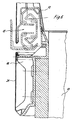
- the lower part 13 of the drawer 1 is connected via adapters 16, which are attached to the side walls 17 of the lower part 13, with the upper part 12, wherein the adapter 16 partially comprise the upper part of the guide rails 15 fixed parts and these components of the guide rails 15th also overlap in the sense of a cover. This is especially out FIG. 5 very clearly visible.
- the adapters 16 are formed in the illustrated embodiment as plastic moldings and provided in the transition region to the upper part 12 each in the front and rear end with integrally molded caps 18, which serve to the respective end-side end portion of a front wall 19 and a rear wall 20 of the lower part 13 final to cover.
- the adapters 16 are closed from the outside by means of plug-on cover plates 21 closed in a smooth-surfaced manner.
- the adapters 16 may alternatively be made as extruded sections instead of as plastic molded parts, in which case separate cover plates 21 could be dispensed with.
- the base of the upper part 12 of the drawer 1 is larger than the base of the lower part 13.
- the base of the upper part corresponds approximately to the base of the entire Stellarias while the base of the lower part 13 of the available size in the base area corresponds ,
- the advantage of the two-part design of the drawer is that only the base size corresponding lower parts 13 manufactured and these need to be attached to a standard components existing upper part.
- the lower part is advantageously equipped with a height-adjustable front panel 4.
Abstract
Description
Die vorliegende Erfindung betrifft einen Sockelschubkasten für den bodenseitigen Bereich eines Stellmöbels, der mit einem gegenüber der Vorderseite des Stellmöbels zurückspringenden Sockelbereich ausgestattet ist, wobei der Schubkasten auch den Sockelbereich des Stellmöbels als Stauraum mitnutzt.The present invention relates to a pedestal drawer for the bottom area of a Stellmöbels, which is equipped with a respect to the front of the furniture recessed base area, wherein the drawer also uses the base area of the Stellmöbels as storage space.
Ein solcher Sockelschubkasten ist z.B. aus Dokument
Unter dem Begriff Stellmöbel wird im Zusammenhang mit der vorliegenden Erfindung ein Schrankmöbel verstanden, welches unmittelbar auf dem Boden eines Raumes aufgestellt wird.The term adjustable furniture is understood in the context of the present invention, a cabinet furniture, which is placed directly on the floor of a room.
So gibt es beispielsweise bei Küchenmöbeln derartige Schränke, die bodenseitig aufgestellt werden und solche, die als Hängeschränke an einer Wand befestigt werden.Thus, for example, in kitchen furniture, such cabinets are placed on the bottom side and those which are attached as wall cabinets to a wall.
Insbesondere im Bereich der Küchenmöbel weisen solche Stellmöbel häufig Schubkästen auf, wobei der untere Schubkasten eines solchen Stellmöbels als bodenseitiger Schubkasten bezeichnet werden kann.In particular, in the field of kitchen furniture such adjustable furniture often drawers, the lower drawer of such a furniture can be referred to as a bottom drawer.
Insbesondere im bodenseitigen Bereich sind bei Stellmöbeln und den bodenseitigen Schubkästen derartiger Stellmöbel Besonderheiten zu beachten, die für weiter oben angeordnete Schubkästen keine Bedeutung haben. So sind derartige Stellmöbel häufig mit einem Sockelbereich ausgestattet, der gegenüber der Vorderseite des Stellmöbels an sich zurückspringt und in dem häufig Stütz- oder Stellfüße zur Höhenjustierung eines derartigen Stellmöbels angeordnet sind, so dass durch Schubkästen häufig nur der Bereich oberhalb des Sockels genutzt werden kann oder im eigentlichen Sockelbereich andere Abmessungen für Schubkästen beachtet werden müssen.Especially in the bottom area special features are to be noted in the case of furniture and the bottom-side drawers such Stellmöbel that have no significance for further upwardly arranged drawers. Thus, such chairs are often equipped with a base area, opposite the front of the furniture jumps back and are often arranged in the support or leveling feet for height adjustment of such a furniture, so that often only the area above the base can be used by drawers or other dimensions must be considered for drawers in the actual base area.
Der vorliegenden Erfindung liegt die Aufgabe zugrunde, einen bodenseitigen Schubkasten für ein Stellmöbel zu schaffen, der den besonderen Anforderungen, die an einen Schubkasten im bodenseitigen Bereich eines Stellmöbels gestellt werden, in äußerst praxisbezogener Weise gerecht wird.The present invention has for its object to provide a bottom-side drawer for a folding furniture, which is the most specific requirements that are placed on a drawer in the bottom area of a furniture, in a very practical way fair.
Diese Aufgabe wird erfindungsgemäß dadurch gelöst, dass der Schubkasten aus einem Oberteil und einem daran angesetzten, sich nahezu bis in den Bodenbereich erstreckenden Unterteil besteht.This object is achieved in that the drawer consists of an upper part and an attached thereto, extending almost to the bottom area lower part.
Eine derartige Lösung bietet den Vorteil, dass beispielsweise an einen vorhandenen Schubkasten, der oberhalb eines Sockelbereiches eines Stellmöbels endet, ein Unterteil angesetzt wird, wobei dann selbstverständlich der Boden des vorhandenen oberen Schubkastenteiles entfernt wird. Das Unterteil kann in seinen Dimensionen dem Sockelbereich eines Stellmöbels angepasst und an einen vorhandenen, in seiner Grundfläche größeren Schubkastenrahmen angesetzt werden. Es wird somit auf einfache Art und Weise ein vergrößerter Schubkasten für den bodenseitigen Bereich eines Stellmöbels geschaffen, der auch dessen Sockelbereich als Stauraum mit nutzt.Such a solution has the advantage that, for example, an existing drawer, which ends above a base region of a Stellmöbels, a lower part is recognized, in which case of course the bottom of the existing upper drawer part is removed. The lower part can be adapted in its dimensions to the base area of a Stellmöbels and attached to an existing, larger in its base drawer frame. It is thus created in a simple manner, an enlarged drawer for the bottom region of a Stellmöbels, which also uses its base area as storage space with.
Weitere Merkmale der Erfindung sind Gegenstand von Unteransprüchen.Further features of the invention are the subject of dependent claims.
In den beigefügten Zeichnungen sind Ausführungsbeispiele der Erfindung dargestellt, die im folgenden näher beschrieben werden.In the accompanying drawings, embodiments of the invention are shown, which are described in more detail below.
Es zeigen:
- Figur 1
- eine perspektivische Darstellung eines Schubkastens gemäß vorliegender Erfindung,
- Figur 2
- eine perspektivische Darstellung des Schubkastens unter Weglassung der Frontblenden,
- Figur 3
- eine perspektivische Teildarstellung eines Unterteiles des Schubkastens nach den
Figuren 1 und2 in einer Sprengbilddarstellung, - Figur 4
- eine perspektivische Darstellung des Unterteiles gemäß
Figur 3 im vollständig montierten Zustand, Figur 5- einen Vertikalschnitt durch den Seitenbereich eines Schubkastens nach den
Figuren 1 - 4 , - Figur 6
- eine gegenüber
Figur 5 Figur 7- eine perspektivische Teilansicht einer Seitenwand des Schubkastens gemäß den
Figuren 1-6 , gesehen von der Innenseite des Schubkastens,
- FIG. 1
- a perspective view of a drawer according to the present invention,
- FIG. 2
- a perspective view of the drawer omitting the front panels,
- FIG. 3
- a partial perspective view of a lower part of the drawer after the
FIGS. 1 and2 in an exploded view, - FIG. 4
- a perspective view of the lower part according to
FIG. 3 in fully assembled condition, - FIG. 5
- a vertical section through the side portion of a drawer after the
Figures 1 - 4 . - FIG. 6
- one opposite
FIG. 5 enlarged partial view of the guide area of the lower area of the drawer, - FIG. 7
- a partial perspective view of a side wall of the drawer according to the
Figures 1-6 , seen from the inside of the drawer,
In den
Das Oberteil 12 besteht - mit Ausnahme eines Bodens - aus den Bauteilen eines herkömmlichen Schubkastens einschließlich einer Frontblende 5.The
An den Seitenwandungen 14 des Oberteiles 12 sind Führungsschienen 15 zur verschiebbaren Lagerung des Schubkastens 1 im Möbelkorpus eines Stellmöbels befestigt.On the
Das Unterteil 13 des Schubkastens 1 ist über Adapter 16, die an den Seitenwandungen 17 des Unterteiles 13 befestigt sind, mit dem Oberteil 12 verbunden, wobei die Adapter 16 die oberteilseitig festgelegten Bestandteile der Führungsschienen 15 teilweise formschlüssig umfassen und diese Bestandteile der Führungsschienen 15 auch noch im Sinne einer Abdeckung überlappen. Dies ist insbesondere aus
Die Adapter 16 sind im dargestellten Ausführungsbeispiel als Kunststoff-Formteile ausgebildet und im Übergangsbereich zum Oberteil 12 jeweils im vorderen und hinteren Endbereich mit einstückig angeformten Abdeckkappen 18 versehen, welche dazu dienen, den jeweiligen stirnseitigen Endbereich einer Vorderwand 19 sowie einer Rückwand 20 des Unterteiles 13 abschließend zu überdecken.The
Die Adapter 16 sind von Ihrer Außenseite her gesehen durch aufsteckbare Abdeckblenden 21 glattflächig verschlossen.The
Die Adapter 16 können alternativ statt als Kunststoff-Formteile auch als Strangprofile gefertigt sein, wobei in diesem Falle separate Abdeckblenden 21 entfallen könnten.The
Wie aus den Zeichnungen hervorgeht, ist die Grundfläche des Oberteiles 12 des Schubkastens 1 größer als die Grundfläche des Unterteiles 13. Dabei entspricht die Grundfläche des Oberteiles in etwa der Grundfläche des gesamten Stellmöbels während die Grundfläche des Unterteiles 13 der zur Verfügung stehenden Größe im Sockelbereich entspricht.As can be seen from the drawings, the base of the
Der Vorteil der zweiteiligen Ausbildung des Schubkastens besteht darin, dass lediglich der Sockelgröße entsprechende Unterteile 13 gefertigt und diese an ein aus serienmäßigen Bauteilen bestehendes Oberteil angesetzt zu werden brauchen.The advantage of the two-part design of the drawer is that only the base size corresponding
Das Unterteil ist vorteilhafterweise mit einer höhenverstellbaren Frontblende 4 ausgestattet. The lower part is advantageously equipped with a height-adjustable front panel 4.
Claims (7)
- Plinth drawer for the floor region of a free-standing furniture unit, which is provided with a plinth region which is set back in relation to the front side of the free-standing furniture unit, the drawer also using the plinth region of the free-standing furniture unit as a stowage space, characterized in that the drawer (1) comprises a top part (12) and a bottom part (13) which is attached to the top part and extends more or less into the floor region.
- Drawer according to Claim 1, characterized in that guide rails (15) with a longitudinal displacement of the drawer within the free-standing furniture unit (2) are fastened on the top part (12), and in that the bottom part (13) is connected via adapters (16), which are fastened on its side walls (17), to those regions of the guide rails (15) which are secured on the top part.
- Drawer according to Claim 2, characterized in that the adapters (16) at least partially cover over those regions of the guide rails (15) which are secured on the top part.
- Drawer according to either of Claims 2 and 3, characterized in that the adapters (16) are in the form of plastic mouldings.
- Drawer according to Claim 4, characterized in that the adapters (16) are each provided, in the front and rear end regions, with integrally formed covering caps (18) which cover over the top, end regions of a front wall (19) and of a rear wall (20) of the bottom part (13).
- Drawer according to Claim 4 or 5, characterized in that the adapters (16) are covered in the region of their outer sides, which are directed away from the drawer (1), by smooth-surfaced covering panels (21).
- Drawer according to Claim 2 or 3, characterized in that the adapters (16) comprise extruded profiles.
Applications Claiming Priority (2)
| Application Number | Priority Date | Filing Date | Title |
|---|---|---|---|
| DE20120242U DE20120242U1 (en) | 2001-12-14 | 2001-12-14 | Bottom drawer for a piece of furniture |
| EP02025320A EP1319352B8 (en) | 2001-12-14 | 2002-11-13 | Lowermost drawer for a furniture |
Related Parent Applications (1)
| Application Number | Title | Priority Date | Filing Date |
|---|---|---|---|
| EP02025320A Division EP1319352B8 (en) | 2001-12-14 | 2002-11-13 | Lowermost drawer for a furniture |
Publications (2)
| Publication Number | Publication Date |
|---|---|
| EP1676500A1 EP1676500A1 (en) | 2006-07-05 |
| EP1676500B1 true EP1676500B1 (en) | 2008-03-26 |
Family
ID=7965156
Family Applications (2)
| Application Number | Title | Priority Date | Filing Date |
|---|---|---|---|
| EP06101481A Expired - Lifetime EP1676500B1 (en) | 2001-12-14 | 2002-11-13 | Lowermost drawer for a piece of furniture |
| EP02025320A Expired - Lifetime EP1319352B8 (en) | 2001-12-14 | 2002-11-13 | Lowermost drawer for a furniture |
Family Applications After (1)
| Application Number | Title | Priority Date | Filing Date |
|---|---|---|---|
| EP02025320A Expired - Lifetime EP1319352B8 (en) | 2001-12-14 | 2002-11-13 | Lowermost drawer for a furniture |
Country Status (5)
| Country | Link |
|---|---|
| EP (2) | EP1676500B1 (en) |
| JP (1) | JP4331468B2 (en) |
| AT (2) | ATE324816T1 (en) |
| DE (3) | DE20120242U1 (en) |
| ES (2) | ES2304759T3 (en) |
Families Citing this family (6)
| Publication number | Priority date | Publication date | Assignee | Title |
|---|---|---|---|---|
| DE20306053U1 (en) * | 2003-04-16 | 2003-06-26 | Hettich Paul Gmbh & Co | Plinth drawer |
| DE102004041861A1 (en) * | 2004-08-27 | 2006-03-16 | Fennel Gmbh & Co. Kg | Bottom drawer |
| DE202013003071U1 (en) * | 2013-04-04 | 2014-07-08 | Grass Gmbh | Device for lifting a front section of a furniture drawer, drawer and furniture |
| DE202013003070U1 (en) * | 2013-04-04 | 2014-07-08 | Grass Gmbh | Device for lifting a front section of a furniture outrigger |
| ES1266379Y (en) * | 2021-01-29 | 2021-08-03 | Azara Consuelo Gazol | SUPPLEMENTAL ACCOMMODATION FOR FURNITURE |
| CN114027642B (en) * | 2021-10-29 | 2023-05-23 | 山东五环电子股份有限公司 | Classified storage device for products for electronic product production |
Family Cites Families (4)
| Publication number | Priority date | Publication date | Assignee | Title |
|---|---|---|---|---|
| DE8903297U1 (en) * | 1989-03-16 | 1989-05-03 | Ninkaplast Gmbh, 4902 Bad Salzuflen, De | |
| AT398265B (en) * | 1990-01-22 | 1994-11-25 | Blum Gmbh Julius | FASTENING DEVICE FOR THE FRONT PANEL OF A DRAWER |
| DE29909515U1 (en) * | 1999-05-31 | 1999-10-07 | Wellmann Gustav Gmbh & Co Kg | Cupboard with base and pull-outs, especially for kitchen furniture |
| JP4039655B2 (en) * | 2000-09-13 | 2008-01-30 | キッチンハウス株式会社 | drawer |
-
2001
- 2001-12-14 DE DE20120242U patent/DE20120242U1/en not_active Expired - Lifetime
-
2002
- 2002-11-13 DE DE50211995T patent/DE50211995D1/en not_active Expired - Lifetime
- 2002-11-13 DE DE50206640T patent/DE50206640D1/en not_active Expired - Lifetime
- 2002-11-13 ES ES06101481T patent/ES2304759T3/en not_active Expired - Lifetime
- 2002-11-13 AT AT02025320T patent/ATE324816T1/en active
- 2002-11-13 EP EP06101481A patent/EP1676500B1/en not_active Expired - Lifetime
- 2002-11-13 EP EP02025320A patent/EP1319352B8/en not_active Expired - Lifetime
- 2002-11-13 AT AT06101481T patent/ATE390063T1/en active
- 2002-11-13 ES ES02025320T patent/ES2261581T3/en not_active Expired - Lifetime
- 2002-12-12 JP JP2002361354A patent/JP4331468B2/en not_active Expired - Fee Related
Also Published As
| Publication number | Publication date |
|---|---|
| ES2261581T3 (en) | 2006-11-16 |
| ATE390063T1 (en) | 2008-04-15 |
| EP1319352A1 (en) | 2003-06-18 |
| EP1319352B8 (en) | 2006-06-28 |
| DE50211995D1 (en) | 2008-05-08 |
| EP1676500A1 (en) | 2006-07-05 |
| DE50206640D1 (en) | 2006-06-08 |
| JP4331468B2 (en) | 2009-09-16 |
| EP1319352B1 (en) | 2006-05-03 |
| ES2304759T3 (en) | 2008-10-16 |
| DE20120242U1 (en) | 2002-02-28 |
| ATE324816T1 (en) | 2006-06-15 |
| JP2003334118A (en) | 2003-11-25 |
Similar Documents
| Publication | Publication Date | Title |
|---|---|---|
| EP1716779B1 (en) | Bottomless drawer with supportive frame therefor | |
| EP2063735B1 (en) | Table, in particular school desk | |
| WO2007122080A2 (en) | System for securing furniture and implements that risk tilting | |
| EP1517625B1 (en) | Height adjustable working table | |
| EP1676500B1 (en) | Lowermost drawer for a piece of furniture | |
| EP3150781B1 (en) | Sanitary cabin device | |
| EP2801291A1 (en) | Furniture fitting to form a pull-out waste collection device | |
| DE202005017755U1 (en) | Trolley for use in e.g. hospital, has frame at which two load bearing side walls are fixed, insertion unit is provided between walls, and tongue-and-groove joint to connect side profiles of extrusion with middle profile of extrusion | |
| EP0813832A2 (en) | Furniture system, especially kitchen furniture system | |
| EP1470768A1 (en) | Cabinet base drawer | |
| DE3247135C2 (en) | ||
| DE102020122707B4 (en) | furniture component | |
| DE102004052311B4 (en) | Furniture with a cabinet-like body in which a swivel bed is hinged | |
| WO2022043570A1 (en) | Side wall with integrated pull-out device including cover elements | |
| EP1989953A1 (en) | Fitting for a corner cupboard with an extendable one-part shelf | |
| WO2008110361A1 (en) | Side grate | |
| DE19616637A1 (en) | Triple sliding rail arrangement for drawers | |
| DE102022126965A1 (en) | Furniture | |
| EP4122438A1 (en) | Medical trolley, in particular ward trolley and care trolley | |
| DE7700989U1 (en) | KITCHEN FURNITURE | |
| DE202013012106U1 (en) | Furniture fitting for forming an extendable waste collection device | |
| DE1816220C3 (en) | Desk | |
| DE202017106175U1 (en) | Furniture with height-adjustable shelves | |
| EP1334674A2 (en) | A piece of kitchen furniture, in particuar a suspended cabinet | |
| DE2601609B2 (en) | EXPANDABLE CARAVAN |
Legal Events
| Date | Code | Title | Description |
|---|---|---|---|
| PUAI | Public reference made under article 153(3) epc to a published international application that has entered the european phase |
Free format text: ORIGINAL CODE: 0009012 |
|
| AC | Divisional application: reference to earlier application |
Ref document number: 1319352 Country of ref document: EP Kind code of ref document: P |
|
| AK | Designated contracting states |
Kind code of ref document: A1 Designated state(s): AT BE BG CH CY CZ DE DK EE ES FI FR GB GR IE IT LI LU MC NL PT SE SK TR |
|
| 17P | Request for examination filed |
Effective date: 20061104 |
|
| 17Q | First examination report despatched |
Effective date: 20061208 |
|
| AKX | Designation fees paid |
Designated state(s): AT BE BG CH CY CZ DE DK EE ES FI FR GB GR IE IT LI LU MC NL PT SE SK TR |
|
| GRAP | Despatch of communication of intention to grant a patent |
Free format text: ORIGINAL CODE: EPIDOSNIGR1 |
|
| GRAS | Grant fee paid |
Free format text: ORIGINAL CODE: EPIDOSNIGR3 |
|
| GRAA | (expected) grant |
Free format text: ORIGINAL CODE: 0009210 |
|
| AC | Divisional application: reference to earlier application |
Ref document number: 1319352 Country of ref document: EP Kind code of ref document: P |
|
| AK | Designated contracting states |
Kind code of ref document: B1 Designated state(s): AT BE BG CH CY CZ DE DK EE ES FI FR GB GR IE IT LI LU MC NL PT SE SK TR |
|
| REG | Reference to a national code |
Ref country code: GB Ref legal event code: FG4D Free format text: NOT ENGLISH |
|
| REG | Reference to a national code |
Ref country code: CH Ref legal event code: EP Ref country code: IE Ref legal event code: FG4D Free format text: LANGUAGE OF EP DOCUMENT: GERMAN |
|
| REF | Corresponds to: |
Ref document number: 50211995 Country of ref document: DE Date of ref document: 20080508 Kind code of ref document: P |
|
| PG25 | Lapsed in a contracting state [announced via postgrant information from national office to epo] |
Ref country code: FI Free format text: LAPSE BECAUSE OF FAILURE TO SUBMIT A TRANSLATION OF THE DESCRIPTION OR TO PAY THE FEE WITHIN THE PRESCRIBED TIME-LIMIT Effective date: 20080326 |
|
| REG | Reference to a national code |
Ref country code: ES Ref legal event code: FG2A Ref document number: 2304759 Country of ref document: ES Kind code of ref document: T3 |
|
| REG | Reference to a national code |
Ref country code: IE Ref legal event code: FD4D |
|
| PG25 | Lapsed in a contracting state [announced via postgrant information from national office to epo] |
Ref country code: SK Free format text: LAPSE BECAUSE OF FAILURE TO SUBMIT A TRANSLATION OF THE DESCRIPTION OR TO PAY THE FEE WITHIN THE PRESCRIBED TIME-LIMIT Effective date: 20080326 Ref country code: SE Free format text: LAPSE BECAUSE OF FAILURE TO SUBMIT A TRANSLATION OF THE DESCRIPTION OR TO PAY THE FEE WITHIN THE PRESCRIBED TIME-LIMIT Effective date: 20080626 Ref country code: PT Free format text: LAPSE BECAUSE OF FAILURE TO SUBMIT A TRANSLATION OF THE DESCRIPTION OR TO PAY THE FEE WITHIN THE PRESCRIBED TIME-LIMIT Effective date: 20080901 Ref country code: CZ Free format text: LAPSE BECAUSE OF FAILURE TO SUBMIT A TRANSLATION OF THE DESCRIPTION OR TO PAY THE FEE WITHIN THE PRESCRIBED TIME-LIMIT Effective date: 20080326 |
|
| ET | Fr: translation filed | ||
| PG25 | Lapsed in a contracting state [announced via postgrant information from national office to epo] |
Ref country code: DK Free format text: LAPSE BECAUSE OF FAILURE TO SUBMIT A TRANSLATION OF THE DESCRIPTION OR TO PAY THE FEE WITHIN THE PRESCRIBED TIME-LIMIT Effective date: 20080326 Ref country code: IE Free format text: LAPSE BECAUSE OF FAILURE TO SUBMIT A TRANSLATION OF THE DESCRIPTION OR TO PAY THE FEE WITHIN THE PRESCRIBED TIME-LIMIT Effective date: 20080326 |
|
| PLBE | No opposition filed within time limit |
Free format text: ORIGINAL CODE: 0009261 |
|
| STAA | Information on the status of an ep patent application or granted ep patent |
Free format text: STATUS: NO OPPOSITION FILED WITHIN TIME LIMIT |
|
| 26N | No opposition filed |
Effective date: 20081230 |
|
| PG25 | Lapsed in a contracting state [announced via postgrant information from national office to epo] |
Ref country code: EE Free format text: LAPSE BECAUSE OF FAILURE TO SUBMIT A TRANSLATION OF THE DESCRIPTION OR TO PAY THE FEE WITHIN THE PRESCRIBED TIME-LIMIT Effective date: 20080326 Ref country code: BG Free format text: LAPSE BECAUSE OF FAILURE TO SUBMIT A TRANSLATION OF THE DESCRIPTION OR TO PAY THE FEE WITHIN THE PRESCRIBED TIME-LIMIT Effective date: 20080626 |
|
| BERE | Be: lapsed |
Owner name: PAUL HETTICH G.M.B.H. & CO. KG Effective date: 20081130 |
|
| PG25 | Lapsed in a contracting state [announced via postgrant information from national office to epo] |
Ref country code: MC Free format text: LAPSE BECAUSE OF NON-PAYMENT OF DUE FEES Effective date: 20081130 |
|
| REG | Reference to a national code |
Ref country code: CH Ref legal event code: PL |
|
| GBPC | Gb: european patent ceased through non-payment of renewal fee |
Effective date: 20081113 |
|
| PG25 | Lapsed in a contracting state [announced via postgrant information from national office to epo] |
Ref country code: BE Free format text: LAPSE BECAUSE OF NON-PAYMENT OF DUE FEES Effective date: 20081130 Ref country code: CY Free format text: LAPSE BECAUSE OF FAILURE TO SUBMIT A TRANSLATION OF THE DESCRIPTION OR TO PAY THE FEE WITHIN THE PRESCRIBED TIME-LIMIT Effective date: 20080326 |
|
| PG25 | Lapsed in a contracting state [announced via postgrant information from national office to epo] |
Ref country code: CH Free format text: LAPSE BECAUSE OF NON-PAYMENT OF DUE FEES Effective date: 20081130 Ref country code: LI Free format text: LAPSE BECAUSE OF NON-PAYMENT OF DUE FEES Effective date: 20081130 |
|
| PG25 | Lapsed in a contracting state [announced via postgrant information from national office to epo] |
Ref country code: GB Free format text: LAPSE BECAUSE OF NON-PAYMENT OF DUE FEES Effective date: 20081113 |
|
| PG25 | Lapsed in a contracting state [announced via postgrant information from national office to epo] |
Ref country code: LU Free format text: LAPSE BECAUSE OF NON-PAYMENT OF DUE FEES Effective date: 20081113 |
|
| PG25 | Lapsed in a contracting state [announced via postgrant information from national office to epo] |
Ref country code: TR Free format text: LAPSE BECAUSE OF FAILURE TO SUBMIT A TRANSLATION OF THE DESCRIPTION OR TO PAY THE FEE WITHIN THE PRESCRIBED TIME-LIMIT Effective date: 20080326 |
|
| PG25 | Lapsed in a contracting state [announced via postgrant information from national office to epo] |
Ref country code: GR Free format text: LAPSE BECAUSE OF FAILURE TO SUBMIT A TRANSLATION OF THE DESCRIPTION OR TO PAY THE FEE WITHIN THE PRESCRIBED TIME-LIMIT Effective date: 20080627 |
|
| PGFP | Annual fee paid to national office [announced via postgrant information from national office to epo] |
Ref country code: NL Payment date: 20141120 Year of fee payment: 13 Ref country code: FR Payment date: 20141118 Year of fee payment: 13 |
|
| REG | Reference to a national code |
Ref country code: NL Ref legal event code: MM Effective date: 20151201 |
|
| REG | Reference to a national code |
Ref country code: FR Ref legal event code: ST Effective date: 20160729 |
|
| PG25 | Lapsed in a contracting state [announced via postgrant information from national office to epo] |
Ref country code: NL Free format text: LAPSE BECAUSE OF NON-PAYMENT OF DUE FEES Effective date: 20151201 |
|
| REG | Reference to a national code |
Ref country code: DE Ref legal event code: R079 Ref document number: 50211995 Country of ref document: DE Free format text: PREVIOUS MAIN CLASS: A47B0088220000 Ipc: A47B0088800000 |
|
| PG25 | Lapsed in a contracting state [announced via postgrant information from national office to epo] |
Ref country code: FR Free format text: LAPSE BECAUSE OF NON-PAYMENT OF DUE FEES Effective date: 20151130 |
|
| PGFP | Annual fee paid to national office [announced via postgrant information from national office to epo] |
Ref country code: ES Payment date: 20161124 Year of fee payment: 15 Ref country code: IT Payment date: 20161124 Year of fee payment: 15 |
|
| PG25 | Lapsed in a contracting state [announced via postgrant information from national office to epo] |
Ref country code: IT Free format text: LAPSE BECAUSE OF NON-PAYMENT OF DUE FEES Effective date: 20171113 |
|
| REG | Reference to a national code |
Ref country code: ES Ref legal event code: FD2A Effective date: 20181226 |
|
| PG25 | Lapsed in a contracting state [announced via postgrant information from national office to epo] |
Ref country code: ES Free format text: LAPSE BECAUSE OF NON-PAYMENT OF DUE FEES Effective date: 20171114 |
|
| PGFP | Annual fee paid to national office [announced via postgrant information from national office to epo] |
Ref country code: DE Payment date: 20201125 Year of fee payment: 19 Ref country code: AT Payment date: 20201117 Year of fee payment: 19 |
|
| REG | Reference to a national code |
Ref country code: DE Ref legal event code: R119 Ref document number: 50211995 Country of ref document: DE |
|
| REG | Reference to a national code |
Ref country code: AT Ref legal event code: MM01 Ref document number: 390063 Country of ref document: AT Kind code of ref document: T Effective date: 20211113 |
|
| PG25 | Lapsed in a contracting state [announced via postgrant information from national office to epo] |
Ref country code: AT Free format text: LAPSE BECAUSE OF NON-PAYMENT OF DUE FEES Effective date: 20211113 |
|
| PG25 | Lapsed in a contracting state [announced via postgrant information from national office to epo] |
Ref country code: DE Free format text: LAPSE BECAUSE OF NON-PAYMENT OF DUE FEES Effective date: 20220601 |