EP0813832A2 - Furniture system, especially kitchen furniture system - Google Patents
Furniture system, especially kitchen furniture system Download PDFInfo
- Publication number
- EP0813832A2 EP0813832A2 EP97108219A EP97108219A EP0813832A2 EP 0813832 A2 EP0813832 A2 EP 0813832A2 EP 97108219 A EP97108219 A EP 97108219A EP 97108219 A EP97108219 A EP 97108219A EP 0813832 A2 EP0813832 A2 EP 0813832A2
- Authority
- EP
- European Patent Office
- Prior art keywords
- connecting element
- furniture system
- tubes
- profiles
- here
- Prior art date
- Legal status (The legal status is an assumption and is not a legal conclusion. Google has not performed a legal analysis and makes no representation as to the accuracy of the status listed.)
- Granted
Links
- 238000005034 decoration Methods 0.000 claims description 2
- 229910052782 aluminium Inorganic materials 0.000 description 7
- XAGFODPZIPBFFR-UHFFFAOYSA-N aluminium Chemical compound [Al] XAGFODPZIPBFFR-UHFFFAOYSA-N 0.000 description 7
- 238000010276 construction Methods 0.000 description 6
- 239000000463 material Substances 0.000 description 6
- 229910052751 metal Inorganic materials 0.000 description 6
- 239000002184 metal Substances 0.000 description 6
- 239000002023 wood Substances 0.000 description 5
- 238000013459 approach Methods 0.000 description 4
- 229910000831 Steel Inorganic materials 0.000 description 3
- 238000009434 installation Methods 0.000 description 3
- 239000004033 plastic Substances 0.000 description 3
- 229910001220 stainless steel Inorganic materials 0.000 description 3
- 239000010935 stainless steel Substances 0.000 description 3
- 239000010959 steel Substances 0.000 description 3
- 230000008719 thickening Effects 0.000 description 3
- XEEYBQQBJWHFJM-UHFFFAOYSA-N Iron Chemical compound [Fe] XEEYBQQBJWHFJM-UHFFFAOYSA-N 0.000 description 2
- 229910000746 Structural steel Inorganic materials 0.000 description 2
- 238000004026 adhesive bonding Methods 0.000 description 2
- 239000000428 dust Substances 0.000 description 2
- 239000013013 elastic material Substances 0.000 description 2
- 230000004048 modification Effects 0.000 description 2
- 238000012986 modification Methods 0.000 description 2
- 238000002360 preparation method Methods 0.000 description 2
- 238000003466 welding Methods 0.000 description 2
- 235000004443 Ricinus communis Nutrition 0.000 description 1
- 240000000528 Ricinus communis Species 0.000 description 1
- 239000000853 adhesive Substances 0.000 description 1
- 230000001070 adhesive effect Effects 0.000 description 1
- 230000000712 assembly Effects 0.000 description 1
- 238000000429 assembly Methods 0.000 description 1
- 238000005452 bending Methods 0.000 description 1
- 230000015572 biosynthetic process Effects 0.000 description 1
- 239000011093 chipboard Substances 0.000 description 1
- 239000006260 foam Substances 0.000 description 1
- 239000011521 glass Substances 0.000 description 1
- 239000010438 granite Substances 0.000 description 1
- 229910052742 iron Inorganic materials 0.000 description 1
- 239000010410 layer Substances 0.000 description 1
- 239000007788 liquid Substances 0.000 description 1
- 238000003801 milling Methods 0.000 description 1
- 239000000123 paper Substances 0.000 description 1
- 238000005192 partition Methods 0.000 description 1
- 239000011120 plywood Substances 0.000 description 1
- 239000002356 single layer Substances 0.000 description 1
- 125000006850 spacer group Chemical group 0.000 description 1
- 230000003068 static effect Effects 0.000 description 1
- 239000004575 stone Substances 0.000 description 1
- 238000011144 upstream manufacturing Methods 0.000 description 1
- 238000005406 washing Methods 0.000 description 1
Images


Classifications
-
- F—MECHANICAL ENGINEERING; LIGHTING; HEATING; WEAPONS; BLASTING
- F16—ENGINEERING ELEMENTS AND UNITS; GENERAL MEASURES FOR PRODUCING AND MAINTAINING EFFECTIVE FUNCTIONING OF MACHINES OR INSTALLATIONS; THERMAL INSULATION IN GENERAL
- F16B—DEVICES FOR FASTENING OR SECURING CONSTRUCTIONAL ELEMENTS OR MACHINE PARTS TOGETHER, e.g. NAILS, BOLTS, CIRCLIPS, CLAMPS, CLIPS OR WEDGES; JOINTS OR JOINTING
- F16B12/00—Jointing of furniture or the like, e.g. hidden from exterior
- F16B12/44—Leg joints; Corner joints
-
- A—HUMAN NECESSITIES
- A47—FURNITURE; DOMESTIC ARTICLES OR APPLIANCES; COFFEE MILLS; SPICE MILLS; SUCTION CLEANERS IN GENERAL
- A47B—TABLES; DESKS; OFFICE FURNITURE; CABINETS; DRAWERS; GENERAL DETAILS OF FURNITURE
- A47B77/00—Kitchen cabinets
-
- A—HUMAN NECESSITIES
- A47—FURNITURE; DOMESTIC ARTICLES OR APPLIANCES; COFFEE MILLS; SPICE MILLS; SUCTION CLEANERS IN GENERAL
- A47B—TABLES; DESKS; OFFICE FURNITURE; CABINETS; DRAWERS; GENERAL DETAILS OF FURNITURE
- A47B47/00—Cabinets, racks or shelf units, characterised by features related to dismountability or building-up from elements
-
- A—HUMAN NECESSITIES
- A47—FURNITURE; DOMESTIC ARTICLES OR APPLIANCES; COFFEE MILLS; SPICE MILLS; SUCTION CLEANERS IN GENERAL
- A47B—TABLES; DESKS; OFFICE FURNITURE; CABINETS; DRAWERS; GENERAL DETAILS OF FURNITURE
- A47B88/00—Drawers for tables, cabinets or like furniture; Guides for drawers
- A47B88/40—Sliding drawers; Slides or guides therefor
- A47B88/423—Fastening devices for slides or guides
- A47B88/43—Fastening devices for slides or guides at cabinet side
-
- A—HUMAN NECESSITIES
- A47—FURNITURE; DOMESTIC ARTICLES OR APPLIANCES; COFFEE MILLS; SPICE MILLS; SUCTION CLEANERS IN GENERAL
- A47B—TABLES; DESKS; OFFICE FURNITURE; CABINETS; DRAWERS; GENERAL DETAILS OF FURNITURE
- A47B96/00—Details of cabinets, racks or shelf units not covered by a single one of groups A47B43/00 - A47B95/00; General details of furniture
- A47B96/14—Bars, uprights, struts, or like supports, for cabinets, brackets, or the like
-
- F—MECHANICAL ENGINEERING; LIGHTING; HEATING; WEAPONS; BLASTING
- F16—ENGINEERING ELEMENTS AND UNITS; GENERAL MEASURES FOR PRODUCING AND MAINTAINING EFFECTIVE FUNCTIONING OF MACHINES OR INSTALLATIONS; THERMAL INSULATION IN GENERAL
- F16B—DEVICES FOR FASTENING OR SECURING CONSTRUCTIONAL ELEMENTS OR MACHINE PARTS TOGETHER, e.g. NAILS, BOLTS, CIRCLIPS, CLAMPS, CLIPS OR WEDGES; JOINTS OR JOINTING
- F16B12/00—Jointing of furniture or the like, e.g. hidden from exterior
- F16B12/02—Joints between panels and corner posts
-
- F—MECHANICAL ENGINEERING; LIGHTING; HEATING; WEAPONS; BLASTING
- F16—ENGINEERING ELEMENTS AND UNITS; GENERAL MEASURES FOR PRODUCING AND MAINTAINING EFFECTIVE FUNCTIONING OF MACHINES OR INSTALLATIONS; THERMAL INSULATION IN GENERAL
- F16B—DEVICES FOR FASTENING OR SECURING CONSTRUCTIONAL ELEMENTS OR MACHINE PARTS TOGETHER, e.g. NAILS, BOLTS, CIRCLIPS, CLAMPS, CLIPS OR WEDGES; JOINTS OR JOINTING
- F16B12/00—Jointing of furniture or the like, e.g. hidden from exterior
- F16B12/40—Joints for furniture tubing
- F16B12/42—Joints for furniture tubing connecting furniture tubing to non-tubular parts
-
- F—MECHANICAL ENGINEERING; LIGHTING; HEATING; WEAPONS; BLASTING
- F16—ENGINEERING ELEMENTS AND UNITS; GENERAL MEASURES FOR PRODUCING AND MAINTAINING EFFECTIVE FUNCTIONING OF MACHINES OR INSTALLATIONS; THERMAL INSULATION IN GENERAL
- F16B—DEVICES FOR FASTENING OR SECURING CONSTRUCTIONAL ELEMENTS OR MACHINE PARTS TOGETHER, e.g. NAILS, BOLTS, CIRCLIPS, CLAMPS, CLIPS OR WEDGES; JOINTS OR JOINTING
- F16B12/00—Jointing of furniture or the like, e.g. hidden from exterior
- F16B12/44—Leg joints; Corner joints
- F16B12/48—Non-metal leg connections
-
- Y—GENERAL TAGGING OF NEW TECHNOLOGICAL DEVELOPMENTS; GENERAL TAGGING OF CROSS-SECTIONAL TECHNOLOGIES SPANNING OVER SEVERAL SECTIONS OF THE IPC; TECHNICAL SUBJECTS COVERED BY FORMER USPC CROSS-REFERENCE ART COLLECTIONS [XRACs] AND DIGESTS
- Y10—TECHNICAL SUBJECTS COVERED BY FORMER USPC
- Y10T—TECHNICAL SUBJECTS COVERED BY FORMER US CLASSIFICATION
- Y10T403/00—Joints and connections
- Y10T403/46—Rod end to transverse side of member
- Y10T403/4602—Corner joint
Definitions
- the invention relates to a furniture system, in particular kitchen furniture system according to the preamble of patent claim 1.
- suitablecase kitchen in which cupboards and functional units such as dishwashers, washing machines, stoves are integrated in a kind of suitcase housing that can be moved on castors and has integrated folding handles for transporting the unit.
- a furniture system in which a self-supporting basic structure is provided with tubes connected to one another by connecting elements, whereby depending on the functionality, shelf boards, side parts, wall parts, flaps, inserts or the like are used in the basic structure and whereby the wall elements are statically load-bearing parts of the furniture.
- the connection of the tubes forming the basic structure is formed by essentially spherical node elements into which the tubes are screwed by means of an end screw.
- the object of the invention is to develop a furniture system with a self-supporting basic structure, which allows a flexible design of kitchen furniture, including all functionalities, that at the same time enables high mobility and has an independent and appealing design.
- the connecting elements of the basic structure each consist of a molded part, which is itself designed as a tube and / or largely closed hollow profile, on which at least one laterally projecting shoulder, which extends over the entire length of the connecting element, is formed is.
- the connecting elements themselves are integrated as vertical components in the basic structure, which replace the pipes and / or profiles that connect them with each other over their length.
- all functionalities can be integrated using the connecting elements formed with the approach. Shelf compartments, side walls, doors, flaps and fittings, as well as drawers can be easily integrated.
- Heavy built-in devices can also be integrated due to the high load-bearing capacity.
- the design of the connecting elements not only enables a modular system that is advantageous from a technical point of view, but also gives the furniture a significant design note due to the connection of the hollow profile consisting of a tube and / or largely closed with a subsequent approach.
- the vertical elements of the basic structure can consist of tubes and / or profiles which extend into the hollow profile of the connecting elements.
- the pipes and / or profiles can extend over the entire length of the connecting element, so that the connecting element is pushed onto the hollow profile as a sleeve, so to speak.
- the hollow profiles do not extend over the entire length in the connecting element, but are only pushed in at the ends to such an extent that secure fastening in the connecting element, for example by clamping, screwing, etc., is possible. This saves material and weight.
- the horizontal pipes and / or profiles, as well as any plates, frames etc. of the basic structure that may be used can be attached of the connecting element.
- the connecting element has the shape of an asymmetrical drop in cross section.
- this shape also enables very good functionality, since no edges are formed here, which make it difficult, for example, to clean the surface.
- the connecting element can have a round or polygonal hollow profile, which is adapted to the shape of the pipes to be connected to one another.
- a recess can be provided on one side of the attachment for the flush reception of components such as wall elements, floors, frames, pipes and plates.
- decorations can be applied to the connecting element, which are engraved and / or printed, for example, in order to additionally give the furniture a designer character.
- connection elements are connected to mounting plates which as such have standardized bores, screw bores, recesses and / or grooves which serve to accommodate components and fittings to be assembled.
- These mounting plates thus contain a number of mounting options, which in particular restrict the provision of a variety of shapes for components for the furniture system. Converting the furniture system is also made easier by the multiple functionality of these mounting plates.
- the connecting element can also be formed in several parts. So the connecting element as such have a teardrop shape, but comprise an externally attachable screen to cover screws of a screw connection that are to be screwed in from the outside.
- an easy-to-install version is provided, since screwing on from the outside is guaranteed after removing the screen.
- the connecting element can also consist of a hollow profile with a shape recess extending over its length and an attachment that can be connected to this hollow profile with a corresponding shape attachment for the positive connection of the two parts.
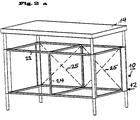
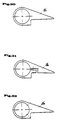
- the basic structure 12 consists in all embodiments of connecting elements 16, which are aligned vertically and into which vertical tubes 18 are also inserted in each case.
- the connecting elements 16 consist of a molded part which is itself designed as a tube and on which a laterally protruding projection 20 which extends over the entire length of the connecting element 16 is formed.
- the horizontal struts, which are designed here as square tubes 22, are attached to this extension 20.
- the basic structure of the furniture system according to the invention is thus carried out by a pipe system which is connected to one another by connecting elements 16.
- the connecting elements 16 and also the usual tubes 18, 22 preferably consist of metal, for example aluminum and stainless steel, but also of wood or plastic.
- Two floor levels are formed by the horizontally extending tubes 22.
- a plate made of metal or wood can also be connected to the connecting elements in a manner not shown here.
- FIG. 1 shows a monoblock in which a functional element, such as a device, is later formed
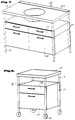
- the exemplary embodiment according to FIG. 2 is designed as a duoblock.
- Two devices can later be accommodated here side by side.
- the horizontal square tubes 22 are here by a central vertical support frame 24, which is also made of square tubes exists, connected to each other.
- the frame in the rear wall area can be stiffened with static aids such as ropes or rods 25 in order to avoid bending and the like.
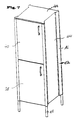
- the embodiment according to FIG. 3 shows a high monoblock in which two functional compartments are arranged one above the other.
- a middle support level is formed by corresponding square tubes 22, the height of which can be fastened to the connecting elements 16 in a freely adjustable manner.
- the tubes 18, which are designed here as tubes with a circular cross section, are only inserted into the respective connecting element 16 to the extent that this is ensured for the necessary stability by means of appropriate connections or constructive safeguards. It is essential that the frame is self-supporting and self-stiffening and that no stability is achieved for the kitchen furniture via the usual side parts used here. As a result, no consideration needs to be given to the design of the side elements. Any functionalities can thus be accommodated in the self-supporting and self-stiffening basic structure 12.
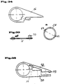
- a duo block is shown in the kitchen furniture according to FIGS. 4 and 5, which essentially contains a basic structure 12 according to the previous embodiment according to FIG. 2. Here, however, an additional horizontal plane has been drawn in to accommodate drawers 26. Larger drawers 28 are arranged in the lower area.
- a wet unit 30 is provided as the support plate 14 integrated basin, the shape of the basin differs in the embodiments according to FIGS. 4 and 5. In the rear area of the wet unit 30 there are in each case strips 32 which form a stop edge on the wet unit 30 and thus prevent objects or liquids from running behind the wet unit.
- 4a shows a wet unit 30 in which the integrated basin is arranged in a large depression 31 which has a step-shaped shoulder 33 in the rear region.
- FIG. 6 shows an example of a preparation unit in which a drawer 28 and a narrower drawer 26 are formed in the frame 12.
- a parking level 36 is formed above the narrower drawer 26.
- a worktop 14 is supported on the base frame 12.
- the preparation unit is movably supported on rollers 34 here.
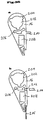
- a "high" monoblock with two devices arranged one above the other in this exemplary embodiment is formed in the basic framework 12 and has two door elements 38 and 40 arranged one above the other.
- a refrigerator is integrated in the upper region by the door element 40 in the exemplary embodiment shown here.
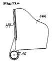
- FIG. 7a shows another embodiment of the invention, here as a "low" monoblock.
- a narrow pull-out 26 is arranged below the plate 14.
- the monoblock In the lower area, the monoblock is designed to be open, the lower level being defined by an inserted grate 158.
- the dash-dotted line indicates a plate that can be installed as an additional intermediate floor 37.
- a connecting element 16 is shown in section. It consists of a tubular hollow profile and a flag-like extension 20, the overall shape of the cross section corresponding to an asymmetrical teardrop shape, as is also shown in FIG. 11.
- the connecting element is manufactured, for example, as an aluminum profile. It can also consist of other materials, such as iron, plastic, etc.
- a tube 18 is shown inside the connecting element 16, which is connected to the connecting element 16 in a rotationally fixed manner.
- a recess is provided on the side of the connecting element, which is directed towards the inside of the furniture.
- a mounting plate 50 is screwed into this recess and is additionally inserted into a corresponding groove of the connecting element via a nose-shaped projection 52.
- the mounting plate has perforated holes, screw holes and a further groove for receiving a side wall 44 which can be screwed in accordingly.
- the more precise structure and function of the mounting plate 50 will be described in more detail below.
- a side wall 44 is inserted between the recess of the mounting plate 50 and the extension 20 and is connected to a screw connection, not shown here.
- FIG. 9 An alternative embodiment of the connecting element is shown in the embodiment according to FIG. 9, in which there is only a comparatively smaller recess for the immediate reception of a side element 44.
- the mounting plate is dispensed with.
- FIG. 10 A further alternative embodiment of the connecting element is shown in FIG. 10.
- the connecting element 16 has no recess, so that the side element 44 is screwed onto the outside of the connecting element 16. This creates a shoulder 46.
- the side element 44 is therefore not designed to be flush with the connecting element 16.
- the paragraph 46 also serves as a door stop for a door.
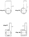
- connecting elements 16 with a drop shape which is asymmetrical in cross section are assumed, as shown in FIG. 11.
- 12 to 25 show shape variants of the connecting elements, which are the same in each case that they consist of a tube and / or largely closed hollow profile and a shoulder.
- the shape is fundamentally different.
- the hollow profile can have a contour which is circular on the inside in cross section.
- this inner contour can also be polygonal.
- a square inner contour is shown in FIGS. 21 and 23, while an octagonal inner contour is shown in FIGS. 24 and 25.
- the tubes 18 of the basic structure 12 which are not shown in any more detail here, are of course also polygonal in a form-adapted manner.
- the formation of polygons in particular makes it easier to adjust and fix a certain angle for the next connected side.
- FIGS. 11 to 25 only partial recesses are shown, into which either a side wall 44 or a mounting plate 50 can be received directly.
- the arrangement and configuration of these recesses is not limited to the embodiments shown here, but can also be applied to the other embodiments.
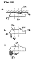
- FIG. 26 and 27 each show connecting elements 16, 11 correspond in their basic form to that according to FIG. 11, but on the outward-facing surface of the extension 20 facing away from the furniture, decorative grooves 56 (in FIG. 26) or 58 (in FIG. 27) are provided.
- FIG. 28 shows a profile 17 which is derived from the shape of the profile 16 according to FIG. 14 by providing two recesses.
- This connecting element 17 forms a central part with which, for example, a central post of a kitchen furniture or basic module can be realized. Additional elements (such as basic modules) can also be attached via the connecting element 17.
- mounting plates 50 not shown here, can be used in the corresponding recesses, via which horizontal pipe connections, wall parts, etc. can then be attached.
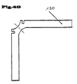
- FIG. 29 shows a connecting element 16 'in which two lugs 20 and 20' are formed at right angles to one another.
- This connecting element can serve as a corner connection in the rear basic scaffold area.
- a rear wall and a side wall can be mounted in corresponding recesses 21 or 21 '.
- FIG. 30 to 34 show different embodiments of connecting elements 16, which differ in the type of fastening of the pipe, not shown here.
- the tube 18 is connected to the connecting element 16 by a fit, by gluing or another detachable or non-detachable connection.
- FIG. 31 shows a connecting element with which the hollow profile of the connecting element is designed as a pipe clamp, so that the pipe or wheel holder 18 is clamped here by means of a corresponding clamping screw connection.
- Fig. 32 two clamping screws are indicated by dashed lines in the connecting element 16, via which a correspondingly inserted tube 18 can also be clamped.
- FIG. 33 and 34 an alternative fastening of the tube 18, which is not shown here, is shown in the connecting element 16.
- a corresponding opening 60 is provided here in the connecting element 16.
- the pipe 18 to be fixed which is shown in FIG. 33a, also has openings 62 and 64 at two points which are diametrically opposite.
- a leaf spring 66 which is shown in FIG. 33, can be pushed through the openings 60 of the connecting element 16 and the openings 62 and 64 of the tube 18 in order to fix the tube 18.
- Protrusions 68 and 70 of different heights which consist, for example, of welded nut heads, are provided for fixing the leaf spring, the protrusion 68 being less high than the protrusion 70.
- the protrusion 68 can be pushed through the comparatively higher opening 62 of the tube 18.
- the projection 70 fits into the recess 60 of the connecting element 16.
- the length of the leaf spring 66 is now dimensioned such that it comes to lie in the assembled position within the recess 64 of the tube 18 with its tongue upstream of the thickening 68, while the thickening 70th comes to rest in the recess 60 of the connecting element 16.
- the tube is secured axially and radially in the connecting element 16.
- the thickening 70 is adapted to the opening 60 so that a clamping set is implemented here.
- the connecting element 16 here has screw holes which permit screwing from the outside of the piece of furniture. After screwing from the outside, one can Screen 72 inserted over the area of the screw connections and fixed by a spring groove connection or a snap-click connection.
- the approach 20 of the connecting element 16 has a recess in which a side wall, not shown here, can be received. This is supported by a corresponding contact surface 73 and screwed according to the dashed line. Due to the different design of the screen 72 and the contact surface 73, different thicknesses of the side wall can be compensated here by exchanging the screen 72.
- 35a and 35b show further exemplary embodiments of the connecting element 16.
- These two connecting elements each have tube receptacles 202. Distributed equally over the circumference, three grooves 204 are excluded from each of these tube receptacles.
- Both connecting elements 16 also have a corresponding bore 206, which is used to fasten cover caps, which are not shown here.
- both embodiments of the connecting elements 16 comprise hollow chambers 208 for receiving corner connectors (cf. embodiment according to FIG. 60a), which are used for fastening floors.
- a projection 210 is integrally formed on the connecting element 16, which is used for fastening to the rear wall.
- a groove 212 is excluded, in which a front stop 214 can be inserted.
- a side plate 216 is inserted into a corresponding receptacle.
- FIG. 36 shows a cross-sectional illustration and a top view of the mounting plate 50, while FIGS. 37 to 39 each show only cross-sectional representations of the mounting plate.
- the mounting plate 50 according to FIG. 36 corresponds to that from FIG. 8.
- a number of pre-drilled holes and screw holes 74 which serve to accommodate standard fittings, are shown.
- a projection 52 is provided on the mounting plate 50, which is used to adjust and prevent lifting in the event of a flat load due to a side wall that applies a pressure load in the interior of the piece of furniture or an outward tensile force of a hinge that is attached in the function bar.
- the projection 52 engages in a corresponding recess in the connecting element 16 (cf. FIG. 8).
- the dimensioning of the side screw connection can be chosen smaller due to this positive engagement of the projection 52 in the corresponding recess of the connecting element 16.
- the projection 52 is arranged at a different location.
- recesses 76 are provided here, into which rubber lips (not shown here) or similar spacers can be inserted in order to compensate for different side wall thicknesses and tolerances of the side walls of side walls (not shown here) to be used, which come to rest in the recess 78. In principle, however, different side thicknesses can also be realized by means of different recesses 78.
- FIG. 38 Another embodiment of the mounting plate is shown in FIG. 38, in which recesses in the mounting plate, which are designated here by 80, are provided, these recesses serving to save weight.
- 39 shows an again varied embodiment of the mounting plate 50, which has two conical guides 82 and 84 and an integrated stop bar 86 with a seal 88.
- the seal 88 is optional and can also be omitted if necessary.
- 39a, 39b and 39c modifications of the embodiment according to FIG. 39 are shown.
- the mounting plate has an inclined contact surface 79, which, by appropriately tightening the mounting screws, enables the space formed by the recess 78 to be narrowed and thus allows it to be adapted to the side wall thickness of the side wall, which is not shown here.
- the stop bar 86 ' is integrally formed on the mounting plate 50.
- the stop bar 86 ' is covered with a U-shaped rubber bar 87.
- the mounting plate 40 shows a mounting plate 50 with a number of different functional fitting parts.
- the mounting plate 50 has a series of bores 74.
- a hinge bracket 94 also shows in the assembled position in FIG. 40.
- Various shelf supports, as are customary in construction, are shown at 96 and 98.
- the strip 100 also represents a shelf support which is fitted in a recess 90 and can be inserted there. With 102 a support angle is designated, which can be connected to the mounting plate by means of screws.
- 104 shows a frame for a floor, which can also be connected to the mounting plate via screw connections.
- the mounting plate offers a multitude of variable mounting options for the individual hardware components, components and functional parts.
- the mounting plate 50 can be perforated, as designated here with the opening 75, in order to also accommodate a frame 104 here, for example.
- the interruption 75 can also be made longer, which leads to material savings and thus to a reduction in costs and weight
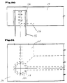
- FIG. 41 shows another typical installation situation of two mounting plates 50 in perspective in the basic framework, which is not shown here.
- a side element 44 is held between the two mounting plates 50.
- a rear wall 106 shown only in section, is inserted in the rear mounting plate 50 in a corresponding groove.
- a conventional slide guide 108 is screwed laterally inwards into corresponding screw holes provided in the mounting plates 50.
- FIG. 42 shows an alternative embodiment of the rear mounting plate 50 which has an integrated stop bar 110 to which the rear wall 106 can be screwed.
- a mounting plate 50 is shown, which also has a stop bar 110 for screwing on the rear wall 106 and additionally a groove 112, into which a further partition can be inserted.
- a separate compartment in the kitchen furniture is thus formed by the further usable intermediate wall (not shown here) and the rear wall 106.
- FIG. 44 has a rear mounting plate 50 which essentially corresponds to that according to FIG. 43.
- a removable clamping strip 114 is inserted in the recess 112, which interacts with a stop strip 116 additionally molded onto the mounting plate and two rubber seals 118 in order to hold a further rear wall 120 which can be removed from the interior of the kitchen furniture.
- a fastening of a rear wall 106 is shown without the provision of an additional mounting plate.
- a connecting element 16 according to an embodiment of FIG. 35a is equipped with an integrally molded projection 210 to which the corresponding rear wall 106 can be screwed.
- a rear wall 106 is screwed to a lower floor 220 so that it protrudes vertically upwards.
- an upper base 222 is arranged with a component 224 arranged underneath, in which a groove 226 is recessed.
- a bent part of a rear wall 106, on which one or more knobs 228 are provided, is inserted into this groove 226.
- FIGS. 45 to 49 Another construction of a connecting element 51 is shown in FIGS. 45 to 49.
- the connecting element 51 is constructed here in two parts and consists of a hollow profile 122 and a shoulder 124.
- a shaped recess is provided in the hollow profile, into which a corresponding shaped shoulder 126 of the shoulder 124 can be inserted and fixed using a screw connection shown here in broken lines.
- a mounting plate or a side part 44 can be fastened to the extension 124.
- the extension 124 can itself also be designed as a mounting plate.
- FIG. 46 shows the hollow profile 122 with the shaped recess into which a correspondingly shaped cover 128 is fitted.
- a double attachment for a corner connection 130 is inserted into the hollow profile 122 at right angles to one another.
- Side walls 44 and a rear wall 106 are also attached to these.
- FIG. 48 shows an extension 124, which is designed here as a mounting plate, in this illustration a hinge bracket 132 or all the others Functional parts is screwed onto which a hinge for the rotatable mounting of a door element can be pushed.
- the worktop 14 can consist of wood, stone, glass, granite, a sheet metal construction or a suitable plastic.
- the worktop has a corresponding bore or sleeve 134 which can be slipped over the ends of the tubes 18.
- angle iron 136 for example, can be fastened between the tubes.
- Corresponding recesses are also provided in the worktop 14, for example for receiving the angle iron 136.
- FIG. 52 in which another section through the worktop is shown. This construction is shown in plan view in FIG. 51, the contours that are actually not visible being shown in dashed lines.
- the worktop 14 is made from a corresponding folded sheet.
- 54 shows in perspective how, for example, the fastening brackets 136 are connected to the tube 18.
- the mounting brackets 136 are welded to a sleeve 138, which are integrally connected to the pipe end of the pipe 18, for example, via welding points 140.
- an adhesive, press fit, screwing or the like can also be provided.
- a corresponding angle 136 is shown here, which has a recess for saving weight. Instead of an angle, a square or a tube can also be used.
- a worktop 14 is shown, which is placed on a tube 18 in the manner shown above.
- the worktop 14 is perforated in its full thickness in the region of the tube 18, so that a further tube piece 138 designed as an adapter can be inserted here.
- a further pipe can be inserted, on which, for example, a wall part, a cover, not shown, or the like is held.
- an end cap 140 or 141 which is also shown in FIG. 56, can also be fitted.
- part 138 is shown in the assembled position.
- a power cable 142 runs through the tube 18 and the tube part 138, which is designed as an adapter and which, for example, supplies power to a lighting arrangement arranged on a rear wall (not shown in more detail here).
- FIGS. 57a and 57b An alternative embodiment for fastening a worktop 14 is shown in FIGS. 57a and 57b.
- a corner element 230 which can also be referred to as an adapter, is inserted in the worktop 14 in a corresponding recess at the corner.
- This adapter 230 is shown in a top view in FIG. 57b.
- the adapter 230 has a sleeve 232 into which the tube 18 can be inserted.
- the tube 18 lies on the collar-shaped end of the sleeve 232 after placement of the plate 14.
- a tube part 138 can be inserted into the worktop 14 from above.
- FIG. 58 shows a single-layer plate and FIG. 59 shows a multi-layer plate or honeycomb construction.
- the base plates can, for example, consist of wood, such as preferably plywood or chipboard, aluminum foam, honeycomb, steel, stainless steel or other flat materials.
- 59 shows an example of a honeycomb construction in which the honeycomb preferably consists of paper, cardboard or aluminum and the cover materials preferably made of aluminum sheet, steel sheet, stainless steel sheet or wood.
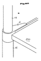
- a profile floor 144 is shown, which is formed as an aluminum profile in one-part or multi-part design. In the case of a multi-part design, the profiles are clipped together or pushed into one another. 60a, a profile floor 144 can be suspended via a correspondingly adapted corner connector 234. The free leg of the corner connector 234 can be inserted, for example, into a receiving opening 208 of a connecting element 16 according to FIGS. 35a and 35b for fastening the profile base 144.
- the base plate 144 is provided with a circumferential corner profile 146, the profile here being able to be designed as a frame and being connected to the base 144 by screws.
- the bottom 144 is formed from a folded sheet metal, the lateral folds serving for stiffening and being able to be circumferential. In a manner not shown here, the corners of the folds are welded for stiffening.
- the additional tab 146 provided in the middle on the underside of the bottom 144 can be connected to the bottom by welding or gluing.
- additional profiles can be made lengthways and / or crosswise be attached to the floor.
- further profiles 148 can also be inserted into the folds, as is explained in more detail using the embodiment according to FIG. 63. In the embodiments according to FIGS.
- the entire floor consists of a floor frame 150 and a support surface 144 which forms the base itself.
- the support surface 144 can now either be folded or placed on a provided tab.
- a further profile can be attached to the frame, as shown in FIG. 65, or the support surface of the floor can have a corresponding stiffening 146, as has already been explained with reference to FIG. 62.
- 61a, 61b and 61c show alternative embodiments of the fastening possibility of the base plate 144.
- a shelf support 147 is shown here, which can be used, for example, in an interruption of the function bar 50, as denoted by 75 in FIG. 40.
- a base 144 made of sheet steel, for example is at least partially bent over in the edge region, so that a connecting lug 145 is formed which can be screwed to a mounting plate 50 (not shown here) by means of corresponding screw holes.
- a base plate 144 which consists for example of sheet metal, is connected to a mounting plate 50 via an angled sheet metal edge 145.
- it can also be a base plate 144 made of any other material.
- FIG. 65 shows the bottom frame 150 according to the embodiment according to FIG. 65 in a top view.
- the floor frame can be non-detachably or releasably connected to one another.
- 67, 68 and 69 are corner connectors for the profiles of the floor frame 150 shown, which are designated 152, 154 and 156 here. These can be connected to each other with the floor profiles by means of a press fit or by screwing. Appropriate milling of the individual profile struts, as shown in FIG. 69, visually conceals the corner connection, ie the bottom is formed without a joint when viewed from the front.
- the corner connectors can be fastened to the connecting element 16 or to the mounting plate 50.
- a lattice frame floor 158 which, in a very simple embodiment, can be inserted into corresponding grooves of the connecting element 16 and fixed there.
- a trellis can be used, for example, as a so-called parking level, i.e. serve as a storage area below the worktop.
- FIG. 72 shows a floor in plan view, which has recesses 160 in the respective corner regions. In the built-in version, as shown in FIG. 71, these recesses lie against the projection formed by the mounting plate 50 and thus offer protection against inadvertent pulling out of the base 144. A corresponding embodiment without a mounting plate 50 is shown in FIG. 71a.
- FIGS. 74a, b and c prefabricated assemblies of floors, sides and rear wall elements are shown, which can be inserted into the basic structure 12 as integrated components.
- the elements are assembled from several parts with simple screw connections or spot welded.
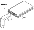
- the 75 shows an integrated side part 162 which integrally integrates two connecting elements 16 and one side part 44.
- the side part 44 is designed here as a hollow chamber aluminum profile to reduce weight.
- the integrated component 162 according to FIG. 75 is shown, in which a groove 164 is additionally provided, into which a mounting plate 50 can be inserted.
- FIG. 8 the embodiment according to FIG. 8 is taken up again, different arrangements of the kitchen cabinet front plate 166 being shown here.
- the kitchen cabinet front plate is arranged behind the center line of the hollow profile of the connecting element 16.
- a gap is possible between the connecting element 16 and the front plate.
- 78 shows an embodiment in which the kitchen front plate lies in front of the center line of the hollow profile of the connecting element 16.
- a gap is formed between the kitchen front plate 166 and the connecting element 16.
- FIG. 79 an arrangement according to FIG.
- a seal 168 is attached as a wiper seal made of elastic material or a brush, which in this exemplary embodiment is received and held in a groove of the connecting element and that Seals the interior of the kitchen furniture against dust, dirt, vermin or the like.
- a seal 170 is formed here as a stop seal made of elastic material or a brush, which is held or glued here in a groove in the mounting plate 50.
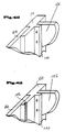
- 80a and 80b each show connecting elements 16, to which tubes 18 each attach. At the lower part there are foot parts and at the upper part tubes 18, as shown for example in Fig. 7a. In contrast to the design according to the embodiment according to FIG. 7a, a bottom 240 is inserted here into corresponding receiving slots of the connecting elements 16.
- an eccentric 250 is shown in dashed lines, which is integrated in the holder and is used for simple fastening.
Abstract
Description
Die Erfindung betrifft ein Möbelsystem, insbesondere Küchenmöbelsystem nach dem Oberbegriff des Patentanspruchs 1.The invention relates to a furniture system, in particular kitchen furniture system according to the preamble of patent claim 1.
Im Bereich der Küchenmöbel haben sich in den letzten Jahrzehnten Einbauküchen durchgesetzt. Hier handelt es sich um Küchenmöbelzeilen, die an die Raumaufteilung der Küche angepaßt sind. Die im Verbund einer Einbauküche fest verbundenen Küchenmöbel weisen nun den Nachteil einer mangelnden Mobilität auf. Dies betrifft einerseits die Möglichkeit eines innerhalb der Küche gewünschten Umstellens und Umorganisierens der Küchenmöbel. Noch häufiger ergeben sich aber die Probleme bei einem Umzug in eine andere Wohnung, der es in der Regel notwendig macht, eine vollständig neue Einbauküche in der neuen Wohnung zu installieren.In the area of kitchen furniture, fitted kitchens have prevailed in recent decades. These are kitchen furniture lines that are adapted to the room layout of the kitchen. The kitchen furniture that is firmly connected in the network of a fitted kitchen now has the disadvantage of a lack of mobility. On the one hand, this concerns the possibility of changing and reorganizing the kitchen furniture as desired within the kitchen. However, the problems of moving to another apartment arise even more frequently, which generally makes it necessary to install a completely new fitted kitchen in the new apartment.
Bereits vor der Einführung von Einbauküchen war es bereits bekannt, Küchen aus Einzelmöbeln, beispielsweise Vorratsschränken, Vitrinen etc. zusammenzustellen. Bei diesen Möbeln handelte es sich allerdings um konventionelle Möbel, die häufig in ihren Abmessungen und ihrem Erscheinungsbild nicht aufeinander abgestimmt waren.Even before the introduction of fitted kitchens, it was already known to put together kitchens from individual furniture, for example pantries, showcases, etc. However, these pieces of furniture were conventional pieces of furniture, which were often not coordinated with one another in terms of their dimensions and appearance.
In allerjüngster Zeit gab es erste Bestrebungen, mobile Küchenelemente zur Verfügung zu stellen. In diesem Zusammenhang ist die sogenannte "Kofferküche" zu nennen, bei der Schränke und Funktionseinheiten, wie Spülmaschine, Waschmaschine, Herd in einer Art Koffergehäuse, das auf Rollen verfahrbar ist und das integrierte Klapp-Tragegriffe zum Transport der Einheit aufweist, integriert sind.In recent times, there have been initial efforts to provide mobile kitchen elements. In this context, the so-called "suitcase kitchen" is to be mentioned, in which cupboards and functional units such as dishwashers, washing machines, stoves are integrated in a kind of suitcase housing that can be moved on castors and has integrated folding handles for transporting the unit.
Andererseits ist im Bereich der Regal- und Büromöbel bereits ein Möbelsystem bekannt, bei dem ein selbsttragendes Grundgerüst mit über Verbindungselement miteinander verbundenen Rohren vorgesehen wird, wobei dann je nach Funktionalität in dem Grundgerüst Regalbretter, Seitenteile, Wandteile, Klappen, Einschübe oder dergleichen eingesetzt sind und wobei auch die Wandelemente statisch tragende Teile des Möbels sind. Die Verbindung der das Grundgerüst bildenden Rohre wird durch im wesentlichen kugelförmige Knotenelemente gebildet, in die die Rohre über eine endseitige Schraube eingeschraubt werden.On the other hand, in the area of shelf and office furniture, a furniture system is already known in which a self-supporting basic structure is provided with tubes connected to one another by connecting elements, whereby depending on the functionality, shelf boards, side parts, wall parts, flaps, inserts or the like are used in the basic structure and whereby the wall elements are statically load-bearing parts of the furniture. The connection of the tubes forming the basic structure is formed by essentially spherical node elements into which the tubes are screwed by means of an end screw.
Aufgabe der Erfindung ist es, ein Möbelsystem mit einem selbsttragenden Grundgerüst zu entwickeln, das eine flexible Gestaltung von Küchenmöbeln unter Einbeziehung sämtlicher Funktionalitäten erlaubt, daß es gleichzeitig eine hohe Mobilität ermöglicht und eine eigenständige und ansprechende Gestaltung aufweist.The object of the invention is to develop a furniture system with a self-supporting basic structure, which allows a flexible design of kitchen furniture, including all functionalities, that at the same time enables high mobility and has an independent and appealing design.
Erfindungsgemäß wird diese Aufgabe ausgehend von einem gattungsgemäßen Möbelsystem durch die kennzeichnenden Merkmale des Hauptanspruchs gelöst. Demnach bestehen die Verbindungselemente des Grundgerüstes jeweils aus einem Formteil, das selbst als Rohr und/oder weitgehend geschlossenes Hohlprofil ausgebildet ist, an welchem zumindest ein seitlich abstehender Ansatz, der sich über die gesamte Länge des Verbindungselements erstreckt, ausgebildet ist. Die Verbindungselemente selbst sind als vertikale Bauelemente im Grundgerüst integriert, die über ihre Länge die Rohre und/oder Profile, die sie miteinander verbinden, ersetzen. In diesem aus genormten Teilen zusammengesetzten selbsttragenden Grundgerüst lassen sich über die mit dem Ansatz ausgebildeten Verbindungselemente sämtliche Funktionalitäten integrieren. So können Regalfächer, Seitenwände, Türen, Klappen und Beschläge, sowie Schubfächer problemlos integriert werden. Aufgrund der hohen Tragfähigkeit können auch schwere Einbaugeräte integriert werden. Die Gestaltung der Verbindungselemente ermöglicht nicht nur ein unter technischen Gesichtspunkten vorteilhaftes Baukastensystem, sondern gibt dem Möbel darüberhinaus aufgrund der Verbindung des aus einem Rohr und/oder weitgehend geschlossenen Hohlprofil mit einem daran anschließenden Ansatz eine signifikante gestalterische Note.According to the invention, this object is achieved on the basis of a generic furniture system by the characterizing features of the main claim. Accordingly, the connecting elements of the basic structure each consist of a molded part, which is itself designed as a tube and / or largely closed hollow profile, on which at least one laterally projecting shoulder, which extends over the entire length of the connecting element, is formed is. The connecting elements themselves are integrated as vertical components in the basic structure, which replace the pipes and / or profiles that connect them with each other over their length. In this self-supporting basic structure made up of standardized parts, all functionalities can be integrated using the connecting elements formed with the approach. Shelf compartments, side walls, doors, flaps and fittings, as well as drawers can be easily integrated. Heavy built-in devices can also be integrated due to the high load-bearing capacity. The design of the connecting elements not only enables a modular system that is advantageous from a technical point of view, but also gives the furniture a significant design note due to the connection of the hollow profile consisting of a tube and / or largely closed with a subsequent approach.
Vorteilhafte Ausgestaltungen der Erfindung ergeben sich aus den sich an den Hauptanspruch anschließenden Unteransprüchen.Advantageous embodiments of the invention result from the subclaims following the main claim.
Demnach können die vertikalen Elemente des Grundgerüsts aus Rohren und/oder Profilen bestehen, die in das Hohlprofil der Verbindungselemente hineinreichen. Dabei können die Rohre und/oder Profile über die gesamte Länge des Verbindungselementes verlaufen, so daß das Verbindungselement sozusagen als Muffe auf das Hohlprofil aufgeschoben ist. Vorteilhaft verlaufen die Hohlprofile aber im Verbindunsgelement nicht über die gesamte Länge, sondern sind jeweils nur an den Enden soweit eingeschoben, daß eine sichere Befestigung in dem Verbindungselement, beispielsweise durch Klemmen, Verschrauben etc. möglich ist. Hierdurch wird entscheidend Material und Gewicht gespart.Accordingly, the vertical elements of the basic structure can consist of tubes and / or profiles which extend into the hollow profile of the connecting elements. The pipes and / or profiles can extend over the entire length of the connecting element, so that the connecting element is pushed onto the hollow profile as a sleeve, so to speak. Advantageously, however, the hollow profiles do not extend over the entire length in the connecting element, but are only pushed in at the ends to such an extent that secure fastening in the connecting element, for example by clamping, screwing, etc., is possible. This saves material and weight.
Die horizontalen Rohre und/oder Profile, sowie eventuell eingesetzte Platten, Rahmen etc. des Grundgerüsts können am Ansatz des Verbindunsgelements befestigt sein.The horizontal pipes and / or profiles, as well as any plates, frames etc. of the basic structure that may be used can be attached of the connecting element.
Von besonderem gestalterischen Reiz ist es, wenn das Verbindungselement im Querschnitt die Form eines asymmetrischen Tropfens aufweist. Diese Formgebung ermöglicht aber auch eine sehr gute Funktionalität, da hier keine Kanten gebildet werden, die beispielsweise eine Reinigung der Oberfläche erschweren.It is of particular design appeal if the connecting element has the shape of an asymmetrical drop in cross section. However, this shape also enables very good functionality, since no edges are formed here, which make it difficult, for example, to clean the surface.
Das Verbindungselement kann ein rundes oder mehreckiges Hohlprofil aufweisen, das jeweils an die Form der miteinander zu verbindenden Rohre angepaßt ist.The connecting element can have a round or polygonal hollow profile, which is adapted to the shape of the pipes to be connected to one another.
Im Verbindungselement kann auf einer Seite des Ansatzes eine Ausnehmung zur bündigen Aufnahme von Bauteilen, wie beispielsweise Wandelementen, Böden, Rahmen, Rohre und Platten vorgesehen sein.In the connecting element, a recess can be provided on one side of the attachment for the flush reception of components such as wall elements, floors, frames, pipes and plates.
Außen können am Verbindungselement Verzierungen aufgebracht sein, die beispielsweise eingraviert und/oder aufgedruckt sind, um dem Möbel zusätzlich noch eine designerische Prägung zu verleihen.On the outside, decorations can be applied to the connecting element, which are engraved and / or printed, for example, in order to additionally give the furniture a designer character.
Besonders vorteilhaft ist es, wenn mit den Verbindungselementen Montageplatten verbunden sind, die als solche genormte Bohrungen, Schraubbohrungen, Ausnehmungen und/oder Nuten aufweisen, die zur Aufnahme von zu montierenden Bauteilen und Beschlägen dienen. Diese Montageplatten beinhalten somit eine Reihe von Montagemöglichkeiten, die insbesondere eine Bereitstellung einer Formenvielfalt von Bauteilen für das Möbelsystem einschränken. Auch der Umbau des Möbelsystems ist durch die Mehrfachfunktionalität dieser Montageplatten erleichtert.It is particularly advantageous if the connecting elements are connected to mounting plates which as such have standardized bores, screw bores, recesses and / or grooves which serve to accommodate components and fittings to be assembled. These mounting plates thus contain a number of mounting options, which in particular restrict the provision of a variety of shapes for components for the furniture system. Converting the furniture system is also made easier by the multiple functionality of these mounting plates.
Gemäß einer alternativen Ausführungsform kann das Verbindungselement auch mehrteilig ausgebildet sein. So kann zwar das Verbindungselement als solches eine Tropfenform aufweisen, jedoch eine von außen zu befestigende aufklemmbare Sichtblende umfassen, um Schrauben einer Schraubverbindung, die von außen eingeschraubt werden sollen, zu verdecken. Hier ist eine montagefreundliche Ausführung an die Hand gegeben, da nach Entfernen der Sichtblende eine Schraubbarkeit von außen gewährleistet ist.According to an alternative embodiment, the connecting element can also be formed in several parts. So the connecting element as such have a teardrop shape, but comprise an externally attachable screen to cover screws of a screw connection that are to be screwed in from the outside. Here, an easy-to-install version is provided, since screwing on from the outside is guaranteed after removing the screen.
Das Verbindungselement kann aber auch aus einem Hohlprofil mit einer sich über seine Länge erstreckenden Formausnehmung und einem mit diesem Hohlprofil verbindbaren Ansatz mit entsprechendem Formansatz zur formschlüssigen Verbindung der beiden Teile bestehen.However, the connecting element can also consist of a hollow profile with a shape recess extending over its length and an attachment that can be connected to this hollow profile with a corresponding shape attachment for the positive connection of the two parts.
Weitere Einzelheiten und Vorteile der Erfindung werden anhand einer Vielzahl von Ausführungsformen zeigenden Zeichnungen näher erläutert. Es zeigen:
- Fig. 1-3:
- Perspektivische Darstellungen unterschiedlicher Ausgestaltungen des Grundgerüsts gemäß einer Ausführungsform der vorliegenden Erfindung,
- Fig. 4-7:
- unterschiedliche Grundmodule in perspektivischer Darstellung,
- Fig. 8-35:
- unterschiedliche Ausführungsformen von Verbindungselementen des erfindungsgemäßen Möbelsystems,
- Fig. 36-39:
- Schnittdarstellungen bzw. eine Draufsicht von verschiedenen Ausführungsformen von Montageplatten des erfindungsgemäßen Möbelsystems,
- Fig. 40-44:
- perspektivische Darstellungen unterschiedlich ausgeformter Montageplatten, teilweise mit Anbauelementen gemäß verschiedenener Ausführungsformen des erfindungsgemäßen Möbelsystems,
- Fig. 45-49:
- Schnittdarstellungen prinzipiell anders gestalteter Ausführungsvarianten des Verbindungselementes,
- Fig. 50-57:
- verschiedene Schnittdarstellungen bzw. Draufsichten durch Teile der Arbeitsplattenbefestigung auf dem Grundgerüst,
- Fig. 58-65:
- unterschiedliche Bodenvarianten zum Einsatz in das Grundgestell des erfindungsgemäßen Möbelsystems,
- Fig. 66:
- einen Bodenrahmen in Draufsicht zum Einsatz in das erfindungsgemäße Möbelsystem,
- Fig. 67-69:
- verschiedene Verbinder für den Bodenrahmen gemäß Fig. 66,
- Fig. 70:
- einen Gitterboden zum Einsatz in das erfindungsgemäße Möbelsystem,
- Fig. 71, 72:
- eine Draufsicht, teilweise geschnitten auf einen Boden mit Ausziehsicherung zum Einsatz in das Möbelsystem und seine Einbausituation,
- Fig. 73, 74:
- unterschiedliche Boden-Seitenteil-Kombinationen zum Einsatz in das erfindungsgemäße Möbelsystem,
- Fig. 75, 76:
- eine alternative Ausführungsform des erfindungsgemäßen Möbelsystems,
- Fig. 77-80:
- Querschnittdarstellungen von unterschiedlichen Einbausituationen im erfindungsgemäßen Möbelsystem.
- Fig. 1-3:
- Perspective representations of different configurations of the basic structure according to an embodiment of the present invention,
- Fig. 4-7:
- different basic modules in perspective,
- Fig. 8-35:
- different embodiments of connecting elements of the furniture system according to the invention,
- Fig. 36-39:
- Sectional representations or a top view of various embodiments of mounting plates of the furniture system according to the invention,
- Fig. 40-44:
- perspective representations of differently shaped mounting plates, some with add-on elements according to various embodiments of the furniture system according to the invention,
- Fig. 45-49:
- Sectional representations of basically different design variants of the connecting element,
- Fig. 50-57:
- different sectional views or top views through parts of the worktop fastening on the basic structure,
- Fig. 58-65:
- different floor variants for use in the base frame of the furniture system according to the invention,
- Fig. 66:
- a floor frame in plan view for use in the furniture system according to the invention,
- Fig. 67-69:
- different connectors for the floor frame according to FIG. 66,
- Fig. 70:
- a grid floor for use in the furniture system according to the invention,
- Fig. 71, 72:
- a plan view, partially cut on a floor with pull-out protection for use in the furniture system and its installation situation,
- 73, 74:
- different floor-side part combinations for use in the furniture system according to the invention,
- 75, 76:
- an alternative embodiment of the furniture system according to the invention,
- Fig. 77-80:
- Cross-sectional representations of different installation situations in the furniture system according to the invention.
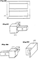
In den Fig. 1 bis 3 ist anhand unterschiedlicher Beispiele der Aufbau eines Grundgerüstes 12 für ein Küchenmöbel 10 dargestellt. In den Fig. 1 und 2 ist auf dem Grundgerüst 12 noch eine Arbeitsplatte 14 aufgelegt. Das Grundgerüst 12 besteht in sämtlichen Ausführungsformen aus Verbindungselementen 16, die vertikal ausgerichtet sind und in die jeweils ebenfalls vertikale Rohre 18 eingesteckt sind. Die Verbindungselemente 16 bestehen aus einem Formteil, das selbst als Rohr ausgebildet ist und an welchem ein seitlich abstehender Ansatz 20, der sich über die gesamte Länge des Verbindungselementes 16 erstreckt, ausgebildet ist. An diesem Ansatz 20 sind die horizontalen Streben, die hier als Vierkantrohre 22 ausgebildet sind, befestigt. Das Grundgerüst des erfindungsgemäßen Möbelsystems ist also durch ein Rohrsystem, welches durch Verbindungselemente 16 miteinander verbunden ist, ausgeführt. Die Verbindungselemente 16 und auch die üblichen Rohre 18, 22 bestehen bevorzugt aus Metall, beispielsweise Aluminium und Edelstahl, aber auch aus Holz oder Kunststoff. Das Grundgerüst, wie es in den Fig. 1 bis 3 dargestellt ist, weist jeweils vier Füße auf, wobei hier jeweils auch Rollen an den Füßen vorgesehen werden können. Es werden durch die horizontal verlaufenden Rohre 22 zwei Bodenebenen gebildet. Statt der Rohre 18, 20 kann in hier nicht dargestellter Art und Weise auch beispielsweise eine Platte aus Metall oder Holz mit den Verbindungselementen verbunden sein.1 to 3, the structure of a
Während die Fig. 1 einen Monoblock zeigt, in dem später ein Funktionselement, wie beispielsweise ein Gerät ausgebildet wird, ist das Ausführungsbeispiel gemäß Fig. 2 als Duoblock ausgebildet. Hier können später zwei Geräte nebeneinander untergebracht werden. Die horizontalen Vierkantrohre 22 sind hier durch einen mittleren vertikalen Tragrahmen 24, der ebenfalls aus Vierkantrohren besteht, miteinander verbunden. Wie in Fig. 2a dargestellt, kann der Rahmen im Rückwandbereich zur Vermeidung von Durchbiegung und dergleichen mit statischen Hilfsmitteln, wie Seilen oder Stäben 25, versteift werden. Die Ausführungsform gemäß Fig. 3 zeigt einen hohen Monoblock, in dem zwei Funktionsfächer übereinander angeordnet sind. Hier ist neben den unteren und oberen Auflageebenen, die durch die horizontal verlaufenden Vierkantrohre 22 gebildet sind, noch eine mittlere Auflageebene durch entsprechende Vierkantrohre 22 ausgebildet, wobei diese in ihrer Höhe an den Verbindungselementen 16 frei justierbar befestigbar sind.1 shows a monoblock in which a functional element, such as a device, is later formed, the exemplary embodiment according to FIG. 2 is designed as a duoblock. Two devices can later be accommodated here side by side. The horizontal
Bei den hier dargestellten Grundgerüsten 12 sind die Rohre 18, die hier als Rohre mit kreisförmigem Querschnitt ausgebildet sind, nur soweit in das jeweilige Verbindungselement 16 eingeführt, wie das für die notwendige Stabilität durch entsprechende Verbindungen bzw. konstruktive Sicherungen gewährleistet ist. Wesentlich ist es, daß das Gestell selbsttragend und selbstversteifend ist und daß über die üblichen hier eingesetzten Seitenteile für das Küchenmöbel keine Stabilität erreicht wird. Hierdurch braucht auf die Ausgestaltung der Seitenelemente keinerlei Rücksicht genommen werden. Es können also beliebige Funktionalitäten in dem selbsttragenden und selbstversteifenden Grundgerüst 12 untergebracht sein.In the
Die Fig. 4 bis 7 geben hier einige Beispiele für entsprechend verwirklichte Funktionalitäten wieder. Dabei ist in dem Küchenmöbel gemäß den Fig. 4 und 5 jeweils ein Duoblock dargestellt, der im wesentlichen ein Grundgerüst 12 gemäß der vorherigen Ausführungsform nach Fig. 2 enthält. Hier ist jedoch jeweils noch eine zusätzliche horizontale Ebene eingezogen um Schubfächer 26 unterzubringen. Im unteren Bereich sind größere Schubfächer 28 angeordnet. Als Auflageplatte 14 ist jeweils eine Naßeinheit 30 mit integriertem Becken aufgesetzt, wobei sich die Form der Becken in den Ausführungsformen gemäß der Fig. 4 und 5 unterscheidet. Im rückwärtigen Bereich der Naßeinheit 30 sind jeweils Leisten 32 aufgelegt, die auf der Naßeinheit 30 eine Anschlagkante bilden und somit verhindern, daß Gegenstände oder Flüssigkeiten hinter die Naßeinheit laufen. In Fig. 4a ist eine Naßeinheit 30 dargestellt, in der das integrierte Becken in einer großflächigen Mulde 31 angeordnet ist, die im hinteren Bereich einen treppenförmigen Absatz 33 aufweist.4 to 7 show some examples of functionalities which have been implemented accordingly. A duo block is shown in the kitchen furniture according to FIGS. 4 and 5, which essentially contains a
In Fig. 6 ist ein Beispiel für eine Zubereitungseinheit dargestellt, bei der in dem Gestell 12 ein Schubfach 28 und ein schmaleres Schubfach 26 ausgebildet ist. Oberhalb des schmaleren Schubfachs 26 ist eine Parkebene 36 gebildet. Auf dem Grundgerüst 12 lagert eine Arbeitsplatte 14 auf. Die Zubereitungseinheit ist hier auf Rollen 34 verfahrbar abgestützt.6 shows an example of a preparation unit in which a
In Fig. 7 ist im Grundgerüst 12 ein "hoher" Monoblock mit zwei in diesem Ausführungsbeispiel übereinander angeordneten Geräten ausgebildet, der zwei übereinander angeordnete Türelemente 38 und 40 aufweist. Im oberen Bereich ist durch das Türelement 40 im hier dargestellten Ausführungsbeispiel ein Kühlschrank integriert. Obenauf liegt eine Deckplatte 42 und seitlich sind Seitenwände 44 mit den Verbindungselementen 16 verbunden.In FIG. 7, a "high" monoblock with two devices arranged one above the other in this exemplary embodiment is formed in the
Fig. 7a zeigt eine andere Ausgestaltung der Erfindung, hier als "niedrigen" Monoblock. Unterhalb der Platte 14 ist hier ein schmaler Auszug 26 angeordnet. Im unteren Bereich ist der Monoblock hier offen gestaltet, wobei die untere Ebene durch einen eingesetzten Gitterrost 158 definiert wird. Mit der strichpunktierten Linie ist eine als zusätzlicher Zwischenboden 37 einbaubare Platte angedeutet.7a shows another embodiment of the invention, here as a "low" monoblock. A narrow pull-out 26 is arranged below the
In Fig. 8 ist ein Verbindungselement 16 im Schnitt dargestellt. Es besteht aus einem rohrförmigen Hohlprofil und einem fahnenartigen Ansatz 20, wobei die Gesamtform des Querschnitts einer asymmetrischen Tropfenform entspricht, wie sie auch in Fig. 11 wiedergegeben ist. In der hier dargestellten Ausführungsform ist das Verbindungselement beispielsweise als Aluminiumprofil gefertigt. Es kann auch aus anderen Materialien, wie Eisen, Kunststoff etc. bestehen. In der hier dargestellten Schnittebene ist im Inneren des Verbindungselements 16 ein Rohr 18 dargestellt, das mit dem Verbindungselement 16 drehfest verbunden ist. In der hier dargestellten Ausführungsform des Verbindungselementes 20 ist eine Ausnehmung auf der Seite des Verbindungselementes vorgesehen, die zur Möbelinnenseite gerichtet ist. In dieser Ausnehmung ist eine Montageplatte 50 eingeschraubt, die zusätzlich über einen nasenförmigen Ansatz 52 in einer entsprechenden Nut des Verbindungselementes eingefügt ist. Die Montageplatte weist je nach Anforderungen Lochbohrungen, Schraubbohrungen und eine weitere Nut zur Aufnahme einer Seitenwand 44, die entsprechend eingeschraubt werden kann, auf. Der genauere Aufbau und die Funktion der Montageplatte 50 wird weiter unten genauer beschrieben. In der Ausführungsform gemäß Fig. 8 ist eine Seitenwand 44 zwischen der Ausnehmung der Montageplatte 50 und dem Ansatz 20 eingesetzt und mit einer hier nicht näher dargestellten Schraubverbindung verbunden.In Fig. 8, a connecting
In der Ausführungsform gemäß Fig. 9 ist eine alternative Ausführungsform des Verbindungselementes dargestellt, in der nur eine vergleichsweise kleinere Ausnehmung zur unmittelbaren Aufnahme eines Seitenelementes 44 vorhanden ist. In dieser Ausführungsform ist auf die Montageplatte verzichtet.An alternative embodiment of the connecting element is shown in the embodiment according to FIG. 9, in which there is only a comparatively smaller recess for the immediate reception of a
Eine weitere alternative Ausgestaltung des Verbindungselementes zeigt die Fig. 10. Hier weist das Verbindungselement 16 jedoch keine Ausnehmung auf, so daß das Seitenelement 44 außen auf das Verbindungselement 16 aufgeschraubt wird. Hierdurch entsteht ein Absatz 46. Im Unterschied zu den Ausführungsformen gemäß der Fig. 8 und 9 ist das Seitenelement 44 also nicht bündig mit dem Verbindungselement 16 ausgebildet. Der Absatz 46 dient gleichzeitig als Türanschlag für eine Tür.A further alternative embodiment of the connecting element is shown in FIG. 10. Here, however, the connecting
In den Ausführungsformen gemäß der Fig. 1 bis 10 und in den weiteren Ausführungsformen ab Fig. 31 wird von Verbindungselementen 16 mit im Querschnitt asymmetrischer Tropfenform ausgegangen, wie diese in Fig. 11 dargestellt ist. Die Fig. 12 bis 25 zeigen aber Formvarianten der Verbindungselemente, denen jeweils gleich ist, daß sie aus einem Rohr und/oder weitgehend geschlossenem Hohlprofil und einem Ansatz bestehen. Die Formgebung ist aber grundsätzlich verschieden. So kann das Hohlprofil, wie in den Fig. 11 bis 17, 19, 20 und 22 eine innen im Querschnitt kreisförmige Kontur aufweisen. Diese Innenkontur kann aber auch mehreckig sein. In den Fig. 21 und 23 ist jeweils eine viereckige Innenkontur gezeigt, während in den Fig. 24 und 25 eine achteckige Innenkontur gezeigt ist. Bei den mehreckigen Innenkonturen sind die hier nicht näher dargestellten Rohre 18 des Grundgerüsts 12 selbstverständlich formangepaßt ebenfalls mehreckig ausgeführt. Gerade die Ausbildung von Vielecken vereinfacht es, einen bestimmten Winkel für die nächste angeschlossene Seite zu justieren und zu fixieren. In den in den Fig. 11 bis 25 dargestellten Rohrgeometrien sind nur teilweise Ausnehmungen dargestellt, in die entweder unmittelbar eine Seitenwand 44 oder eine Montageplatte 50 aufnehmbar sind. Die Anordnung und Ausgestaltung dieser Ausnebmungen ist aber nicht auf die hier dargestellten Ausführungsformen beschränkt, sondern kann auch auf die übrigen Ausführungsformen angewandt werden.In the embodiments according to FIGS. 1 to 10 and in the further embodiments from FIG. 31, connecting
In den Fig. 26 und 27 sind jeweils Verbindungselemente 16 dargestellt, die von ihrer Grundform her demjenigen gemäß Fig. 11 entsprechen, jedoch auf der vom Möbel weg weisenden nach außen liegenden Fläche des Ansatzes 20 Verzierungsriefen 56 (in Fig. 26) bzw. 58 (in Fig. 27) vorgesehen sind. Hierdurch wird die Profilsichtseite entsprechend attraktiver gestaltet. In Fig. 28 ist ein Profil 17 dargestellt, das von der Form des Profils 16 gemäß Fig. 14 durch Vorsehen von zwei Ausnehmungen abgeleitet ist. Dieses Verbindungselement 17 bildet ein Mittelteil, mit dem beispielsweise ein mittlerer Pfosten eines Küchenmöbels bzw. Grundmoduls zu realisieren ist. Über das Verbindungselement 17 können auch weitere Elemente (wie beispielsweise Grundmodule) angebaut werden. In den entsprechenden Ausnehmungen können jeweils beispielsweise hier nicht näher dargestellte Montageplatten 50 eingesetzt werden, über die dann horizontale Rohrverbindungen, Wandteile etc. ansetzbar sind.26 and 27 each
In Fig. 29 ist ein Verbindungselement 16' dargestellt, bei dem zwei im rechten Winkel zueinander stehende Ansätze 20 und 20' angeformt sind. Dieses Verbindungselement kann als Eckverbindung im hinteren Grundgerüstbereich dienen. In entsprechende Ausnehmungen 21 bzw. 21' können beispielsweise eine Rückwand und eine Seitenwand montiert werden.FIG. 29 shows a connecting element 16 'in which two
Anhand der Fig. 30 bis 34 zeigen unterschiedliche Ausführungsformen von Verbindungselementen 16, die sich in der Art der Befestigung des hier nicht näher dargestellten Rohres unterscheiden. In dem Ausführungsbeispiel gemäß Fig. 30 wird das Rohr 18 durch eine Passung, durch Kleben oder eine sonstige lösbare bzw. unlösbare Verbindung mit dem Verbindungselement 16 verbunden. In Fig. 31 ist ein Verbindungselement dargestellt, mit dem das Hohlprofil des Verbindungselements als Rohrschelle ausgebildet ist, so daß hier über eine entsprechende Klemmverschraubung eine Klemmung des Rohres oder Radhalter 18 erfolgt.30 to 34 show different embodiments of connecting
In Fig. 32 sind mit strichlierten Linien in dem Verbindungselement 16 zwei Klemmschrauben angedeutet, über die ein entsprechend eingesetztes Rohr 18 ebenfalls verklemmbar ist.In Fig. 32, two clamping screws are indicated by dashed lines in the connecting
In den Fig. 33 und 34 ist eine alternative Befestigung des Rohres 18, das hier nicht näher dargestellt ist, im Verbindungselement 16 dargestellt. Hier ist im Verbindungselement 16 eine entsprechende Durchbrechung 60 vorgesehen. Auch das festzulegende Rohr 18, das in der Fig. 33a dargestellt ist, weist an zwei Stellen, die diametral gegenüberliegen, Durchbrechungen 62 und 64 auf. Durch die Durchbrechungen 60 des Verbindungselements 16 und die Durchbrechungen 62 und 64 des Rohres 18 ist eine Blattfeder 66, die in Fig. 33 dargestellt ist, zur Festlegung des Rohres 18 schiebbar. Zur Festlegung der Blattfeder sind verschieden hohe Vorsprünge 68 und 70, die beispielsweise aus angeschweißten Mutterköpfen bestehen, vorgesehen, wobei der Vorsprung 68 weniger hoch ist als der Vorsprung 70. Der Vorsprung 68 kann durch die vergleichsweise höhere Durchbrechung 62 des Rohres 18 geschoben werden. Der Vorsprung 70 paßt in die Ausnehmung 60 des Verbindungselementes 16. Die Länge der Blattfeder 66 ist nun so bemessen, daß sie sich mit ihrer der Verdickung 68 vorgelagerten Zunge in montierter Stellung innerhalb der Ausnehmung 64 des Rohres 18 zu liegen kommt, während die Verdickung 70 in der Ausnehmung 60 des Verbindungselements 16 zu liegen kommt. Hierdurch ist das Rohr axial und radial im Verbindungselement 16 gesichert. Die Verdickung 70 ist an die Durchbrechung 60 angepaßt, so daß hier ein Klemmset verwirklicht ist.33 and 34, an alternative fastening of the
In Fig. 35 ist eine weitere alternative Ausgestaltung des Verbindungselementes 16 gezeigt. Das Verbindungselement 16 weist hier Schraublöcher auf, die eine Verschraubung von der Außenseite des Möbels zulassen. Nach der Verschraubung von außen kann eine Sichtblende 72 über dem Bereich der Schraubverbindungen gesteckt und durch eine Federnutverbindung oder eine Schnapp-Klick-Verbindung festgelegt werden. Der Ansatz 20 des Verbindungselements 16 hat eine Ausnehmung, in der eine hier nicht näher dargestellte Seitenwand aufgenommen werden kann. Diese wird durch eine entsprechende Anlagefläche 73 aufgestützt und entsprechend der strichlierten Linie verschraubt. Durch unterschiedliche Ausbildung der Sichtblende 72 und die Anlagefläche 73 können hier durch Austausch der Sichtblende 72 unterschiedliche Stärken der Seitenwand ausgeglichen werden.35 shows a further alternative embodiment of the connecting
In Fig. 35a und Fig. 35b sind weitere Ausführungsbeispiele des Verbindungselementes 16 gezeigt. Diese beiden Verbindungselemente weisen jeweils Rohraufnahmen 202 auf. Gleich verteilt über den Umfang sind an diesen Rohraufnahmen jeweils drei Nuten 204 ausgenommen. Beide Verbindungselemente 16 weisen auch eine entsprechende Bohrung 206 auf, die zur Befestigung von Abdeckkappen, die hier nicht näher dargestellt sind, dient.35a and 35b show further exemplary embodiments of the connecting
Zusätzlich umfassen beide Ausführungsformen der Verbindungselemente 16 Hohlkammern 208 zur Aufnahme von Eckverbindern (vgl. Ausführungsform gemäß Fig. 60a), die zur Befestigung von Böden dienen. In der Ausführungsform gemäß Fig. 35a ist an dem Verbindungselement 16 einstückig ein Vorsprung 210 angeformt, der zur Rückwandbefestigung dient.In addition, both embodiments of the connecting
In der Ausführungsform gemäß Fig. 35b des Verbindungselements 16 ist eine Nut 212 ausgenommen, in welche ein Frontanschlag 214 einsetzbar ist. In der Ausführungsform gemäß Fig. 35b ist in eine entsprechende Aufnahme ein Seitenblech 216 eingesetzt.In the embodiment according to FIG. 35b of the connecting
In den Fig. 36 bis 39 sind unterschiedliche Ausgestaltungen der Montageplatte 50 gezeigt. Die Fig. 36 zeigt dabei eine Querschnittdarstellung und eine Draufsicht der Montageplatte 50, während die Fig. 37 bis 39 jeweils nur Querschnittdarstellungen der Montageplatte zeigen. Die Montageplatte 50 gemäß Fig. 36 entspricht derjenigen aus Fig. 8. In der Draufsicht sind eine Reihe von vorgebohrten Löchern und Schraubbohrungen 74, die zur Aufnahme von Standardbeschlägen dienen, dargestellt. Seitlich ist ein Vorsprung 52 an der Montageplatte 50 vorgesehen, der zur Justierung und Verhinderung des Abhebens bei flächiger Belastung durch eine in Innenrichtung des Möbels eine Drucklast aufbringende Seitenwand oder eine nach außen gerichtete Zugkraft eines Scharniers, das in der Funktionsleiste angebracht ist, dient. Der Vorsprung 52 greift in eine entsprechende Ausnehmung im Verbindungselement 16 ein (vgl. Fig. 8). Insgesamt kann die Dimensionierung der Seitenverschraubung aufgrund dieses formschlüssigen Eingriffs des Vorsprungs 52 in die entsprechende Ausnehmung des Verbindungselements 16 kleiner gewählt werden.36 to 39 different configurations of the mounting
Bei der in Fig. 37 dargestellten Montageplatte 50 ist der Vorsprung 52 an einer anderen Stelle angeordnet. Zusätzlich sind hier Ausnehmungen 76 vorgesehen, in welche Gummilippen (hier nicht näher dargestellt) oder ähnliche Abstandhalter einsetzbar sind, um unterschiedliche Seitenwandstärken, und Toleranzen der Seitenwände von hier nicht näher dargestellten einzusetzenden Seitenwänden, die in der Ausnehmung 78 zu liegen kommen, auszugleichen. Grundsätzlich können aber durch unterschiedliche Ausnehmungen 78 auch unterschiedliche Seitenstärken realisiert werden. Eine weitere Ausführungsform der Montageplatte ist in Fig. 38 gezeigt, bei der Ausnehmungen in der Montageplatte, die hier mit 80 bezeichnet sind, vorgesehen sind, wobei diese Ausnehmungen zur Gewichtsersparnis dienen. Schließlich zeigt die Fig. 39 eine wiederum variierte Ausführungsform der Montageplatte 50, die zwei konische Führungen 82 und 84 und eine integrierte Anschlagleiste 86 mit Dichtung 88 aufweist. Die Dichtung 88 ist optional und kann gegebenenfalls auch weggelassen werden. In den Ausführungen gemäß der Fig. 39a, 39b und 39c sind Abwandlungen der Ausführungsform gemäß Fig. 39 dargestellt. In der Abwandlung gemäß Fig. 39a weist die Montageplatte eine schräge Anlagefläche 79 auf, die durch entsprechendes Anziehen der Montageschrauben eine Verengung des durch die Ausnehmung 78 gebildeten Zwischenraums und damit eine Anpassung an die Seitenwandstärke der hier nicht näher dargestellten Seitenwand ermöglichen.In the mounting
Bei der Ausführungsform gemäß Fig. 39b ist die Anschlagleiste 86' fest an der Montageplatte 50 angeformt. In Fig. 39c wiederum ist die Anschlagleiste 86' mit einer U-förmigen Gummileiste 87 ummantelt.In the embodiment according to FIG. 39b, the stop bar 86 'is integrally formed on the mounting
In Fig. 40 ist eine Montageplatte 50 mit einer Reihe unterschiedlicher Funktionsbeschlagteile dargestellt. Die Montageplatte 50 weist eine Reihe von Bohrungen 74 auf. Darüberhinaus sind Einschnitte bzw. Ausnehmungen 90, 92 vorhanden. Ein Scharnierböckchen 94, weist in montierter Stellung ebenfalls in der Fig. 40 dargestellt. Mit 96 und 98 sind verschiedene Fachbodenträger, wie sie bauüblich sind, dargestellt. Auch die Leiste 100 stellt einen Fachbodenträger dar, der in einer Ausnehmung 90 eingepaßt ist und dort eingeschoben werden kann. Mit 102 ist ein Auflagewinkel bezeichnet, der über Schrauben mit der Montageplatte verbindbar ist. Schließlich zeigt 104 einen Rahmen für einen Boden, der ebenfalls über Schraubverbindungen mit der Montageplatte verbindbar ist. Die Montageplatte bietet eine Vielzahl von variablen Anbaumöglichkeiten für die einzelnen Beschlagteile, Bauteile und Funktionsteile. Die Montageplatte 50 kann durchbrochen sein, wie hier mit dem Durchbruch 75 bezeichnet, um hier beispielsweise auch einen Rahmen 104 aufzunehmen. Die Unterbrechung 75 kann auch länger ausgebildet sein, was zur Materialeinsparung und damit zu einer Reduzierung der Kosten und des Gewichts führt.40 shows a mounting
In Fig. 41 ist eine andere typische Einbausituation von zwei Montageplatten 50 in dem hier nicht näher dargestellten Grundgerüst perspektivisch dargestellt. Zwischen den beiden Montageplatten 50 ist ein Seitenelement 44 gehalten. Zusätzlich ist in der hinteren Montageplatte 50 in einer entsprechenden Nut eine hier nur geschnitten dargestellte Rückwand 106 eingesetzt. Seitlich nach innen ist in entsprechend in den Montageplatten 50 vorgesehene Schraubbohrungen eine übliche Schubführung 108 angeschraubt.FIG. 41 shows another typical installation situation of two mounting
In der Fig. 42 ist eine alternative Ausführungsform der rückwärtigen Montageplatte 50 dargestellt, die eine integrierte Anschlagleiste 110 aufweist, an die die Rückwand 106 anschraubbar ist. In der Ausführungsform gemäß Fig. 43 ist eine Montageplatte 50 dargestellt, die ebenfalls eine Anschlagleiste 110 zum Anschrauben der Rückwand 106 aufweist und zusätzlich eine Nut 112, in die eine weitere Zwischenwand einsetzbar ist. Durch die hier nicht näher dargestellte weitere einsetzbare Zwischenwand und die Rückwand 106 ist somit ein abgetrenntes Fach im Küchenmöbel gebildet. Fig. 44 weist eine hintere Montageplatte 50 auf, die im wesentlichen derjenigen gemäß Fig. 43 entspricht. Hier ist allerdings in der Ausnehmung 112 eine abnehmbare Klemmleiste 114 eingesetzt, die mit einer an der Montageplatte zusätzlich angeformten Anschlagleiste 116 und zwei Gummidichtungen 118 zusammenwirkt, um eine vom Inneren des Küchenmöbels aus abnehmbare weitere Rückwand 120 zu halten.42 shows an alternative embodiment of the
In der Ausführungsform gemäß Fig. 44a ist eine Befestigung einer Rückwand 106 ohne das Vorsehen einer zusätzlichen Montageplatte gezeigt. Hier ist ein Verbindungselement 16 entsprechend einer Ausführungsform der Fig. 35a mit einem einstückig angeformten Ansatz 210 ausgestattet, an den die entsprechende Rückwand 106 anschraubbar ist.In the embodiment according to FIG. 44a, a fastening of a
In der Ausführungsform gemäß Fig. 44b ist eine Rückwand 106 an einen unteren Boden 220 geschraubt, so daß sie senkrecht nach oben absteht. In der Ausführungsform gemäß Fig. 44c ist ein oberer Boden 222 mit einem darunter angeordneten Bauelement 224 angeordnet, in welchem eine Nut 226 ausgenommen ist. In dieser Nut 226 wird ein umgebogener Teil einer Rückwand 106, an dem ein oder mehrere Noppen 228 vorgesehen sind, eingeschoben. Dies stellt eine weitere Möglichkeit der Rückwandbefestigung dar. Zu einer stabilen Befestigung einer Rückwand 106 werden die in den Fig. 44a, 44b, und 44c wiedergegebenen Befestigungsmöglichkeiten miteinander kombiniert.In the embodiment according to FIG. 44b, a
In den Fig. 45 bis 49 ist eine andere Konstruktionsweise eines Verbindungselements 51 dargestellt. Das Verbindungselement 51 ist hier zweiteilig aufgebaut und besteht aus einem Hohlprofil 122 und einem Ansatz 124. Im Hohlprofil ist eine Formausnehmung vorgesehen, in die ein entsprechender Formansatz 126 des Ansatzes 124 einschiebbar und über eine hier strichliert dargestellte Schraubverbindung festlegbar ist. An dem Ansatz 124 kann, wie bereits zuvor ausführlich dargelegt, eine Montageplatte oder aber unmittelbar ein Seitenteil 44 befestigt sein. Gemäß einer weiteren Ausführungsform kann der Ansatz 124 aber auch selbst als Montageplatte ausgebildet sein.Another construction of a connecting
In Fig. 46 ist das Hohlprofil 122 mit der Formausnehmung dargestellt, in welche eine entsprechend formangepaßte Abdeckung 128 eingepaßt ist. In Fig. 47 ist in das Hohlprofil 122 ein rechtwinklig zueinander ausgerichteter Doppelansatz für eine Eckverbindung 130 eingesetzt. An diesen sind ebenfalls Seitenwände 44 bzw. eine Rückwand 106 befestigt. In Fig. 48 ist ein Ansatz 124 dargestellt, der hier als Montageplatte ausgebildet ist, wobei in dieser Darstellung ein Scharnierböckchen 132 oder alle übrigen Funktionsteile angeschraubt ist, auf dem ein bauübliches Scharnier zur drehbaren Lagerung eines Türelementes aufschiebbar ist.46, the
In Fig. 49 ist nochmals das Ansatzteil 130 mit den beiden zueinander rechtwinklig stehenden Ansätzen gezeigt. Bezüglich der Verwendung und Möglichkeit der Abänderung der Verbindungselemente gemäß der Fig. 45 bis 49 kann auf die vorherigen Ausführungen zum Verbindungselement 51 bzw. 16 verwiesen werden.In Fig. 49 the
Anhand der Fig. 50 bis 57 wird die Befestigung einer Arbeitsplatte 14 auf dem Grundgerüst 12 und hier auf den vertikalen Rohren 18 des Grundgerüsts 12 dargestellt. Grundsätzlich kann die Arbeitsplatte 14 beliebig aus Holz, Stein, Glas, Granit, einer Blechkonstruktion oder einem geeigneten Kunststoff bestehen. Die Arbeitsplatte weist eine entsprechende Bohrung oder Muffe 134 auf, die über die Enden der Rohre 18 stülpbar ist. Zwischen den Rohren können, wie in Fig. 50 in gestrichelter Linie dargestellt, z.B. Winkeleisen 136 befestigt sein. In der Arbeitsplatte 14 sind auch hier entsprechende Ausnehmungen beispielsweise zur Aufnahme des Winkeleisens 136 vorgesehen. Dies ist in der Fig. 52 dargestellt, in welcher ein anderer Schnitt durch die Arbeitsplatte wiedergegeben ist. In Fig. 51 ist diese Konstruktion in Draufsicht dargestellt, wobei die eigentlich nicht sichtbaren Konturen in strichlierten Linien wiedergegeben sind. In Fig. 53 ist die Arbeitsplatte 14 aus einem entsprechenden gekanteten Blech gefertigt. In Fig. 54 ist perspektivisch dargestellt, wie beispielsweise die Befestigungswinkel 136 mit dem Rohr 18 verbunden sind. Hier sind die Befestigungswinkel 136 mit einer Muffe 138 verschweißt, die beispielsweise über Schweißpunkte 140 mit dem Rohrende des Rohres 18 stoffschlüßig verbunden sind. Statt der Schweißverbindung kann aber auch eine Klebung, Preßpassung, Schraubung oder dergleichen vorgesehen sein.50 to 57, the attachment of a
In Fig. 55 sind verschiedene Auflagemöglichkeiten dargestellt, die anstelle des Befestigungswinkels 136 verwendet werden können. So ist hier ein entsprechender Winkel 136 dargestellt, der eine Ausnehmung zur Gewichtsersparnis aufweist. Statt eines Winkels kann aber auch ein Vierkant oder ein Rohr verwendet werden.55 shows various support options that can be used instead of the mounting
In den Fig. 56 und 57 ist jeweils eine Arbeitsplatte 14 dargestellt, die auf ein Rohr 18 in der zuvor dargestellten Art und Weise aufgesetzt ist. Hier ist allerdings die Arbeitsplatte 14 im Bereich des Rohres 18 in ihrer vollen Dicke durchbrochen, so daß hier ein weiteres als Adapter ausgebildetes Rohrstück 138 einsteckbar ist. In den oberen erweiterten Teil des Rohrstücks 138 kann ein weiteres Rohr einsteckbar sein, an dem beispielsweise ein Wandteil, eine nicht näher dargestellte Verblendung oder dergleichen gehalten ist. Statt des rohrförmigen Teils 138 kann auch eine Abschlußkappe 140 oder 141, die ebenfalls in Fig. 56 dargestellt ist, aufgesetzt werden. In Fig. 57 ist das Teil 138 in montierter Stellung gezeigt. Durch das Rohr 18 und das als Adapter ausgebildete Rohrteil 138 verläuft ein Stromkabel 142, das beispielsweise eine an einer Rückwand angeordnete Beleuchtung mit Strom versorgt (hier nicht näher dargestellt).56 and 57, a
In den Fig. 57a und 57b ist eine alternative Ausführungsform für eine Befestigung einer Arbeitsplatte 14 gezeigt. In der Arbeitsplatte 14 ist in einer entsprechenden Ausnehmung an der Ecke ein Eckelement 230, das auch als Adapter bezeichnet werden kann, eingesetzt. Dieser Adapter 230 ist in Draufsicht in der Fig. 57b gezeigt. Der Adapter 230 weist eine Hülse 232 auf, in welche das Rohr 18 einsteckbar ist. Das Rohr 18 liegt nach Aufsetzen der Platte 14 am kragenförmigen Ende der Hülse 232 an. Von oben in die Arbeitsplatte 14 kann, wie zuvor beschrieben, ein Rohrteil 138 eingesteckt werden.An alternative embodiment for fastening a
In den Fig. 58 bis 65 sind Bodenplatten und Parkebenen 144 dargestellt. Dabei ist in Fig. 58 eine Einschichtplatte und Fig. 59 eine Mehrschichtplatte oder Wabenkonstruktion dargestellt. Die Bodenplatten können beispielsweise aus Holz, wie vorzugsweise Sperrholz oder Spanplatte, Aluminiumschaum , Waben, Stahl, Edelstahl oder anderen flächigen Materialien bestehen. In Fig. 59 ist beispielhaft eine Wabenkonstruktion gezeigt, bei der die Wabe bevorzugt aus Papier, Pappe oder Aluminium besteht und die Deckmaterialien bevorzugt aus Aluminiumblech, Stahlblech, Edelstahlblech oder Holz.58 to 65, base plates and
In Fig. 60 ist ein Profilboden 144 dargestellt, der als Aluminiumprofil in einteiliger oder mehrteiliger Ausführung gebildet ist. Bei mehrteiliger Ausführung werden die Profile miteinander verklippst oder ineinander geschoben. Gemäß Fig. 60a kann ein Profilboden 144 über einen entsprechend angepaßten Eckverbinder 234 aufgehängt werden. Der freie Schenkel des Eckverbinders 234 kann beispielsweise in eine Aufnahmeöffnung 208 eines Verbindungselements 16 nach den Fig. 35a bzw. 35b zur Befestigung des Profilbodens 144 gesteckt werden. Bei der Ausführungsform der Bodenplatte 144 nach Fig. 61 ist die Bodenplatte 144 mit einem umlaufenden Eckprofil 146 versehen, wobei das Profil hier als Rahmen ausgebildet sein kann und über Schrauben mit dem Boden 144 verbunden ist. Bei der in Fig. 62 dargestellten Ausführungsform ist der Boden 144 aus einem gekanteten Blech gebildet, wobei die seitlichen Abkantungen zur Versteifung dienen und umlaufend ausgebildet sein können. In hier nicht dargestellter Art und Weise sind die Ecken der Abkantungen zur Versteifung verschweißt. Die zusätzlich in der Mitte vorgesehene Lasche 146 an der Unterseite des Bodens 144 kann durch Schweißung oder Kleben mit dem Boden verbunden sein. Um eine höhere Steifigkeit des Bodens 144 zu erreichen können längs und/oder quer zusätzliche Profile an dem Boden befestigt sein. Es können zusätzlich auch noch weitere Profile 148 in die Abkantungen eingelegt werden, wie das anhand der Ausführungsform gemäß Fig. 63 näher erläutert ist. In den Ausführungsformen gemäß der Fig. 64 und 65 besteht der gesamte Boden aus einem Bodenrahmen 150 und einer den Boden selbstbildenden Auflagefläche 144. Die Auflagefläche 144 kann nun entweder abgekantet werden oder auf eine vorgesehene Lasche aufgelegt sein. Zur zusätzlichen Versteifung kann ein weiteres Profil am Rahmen befestigt sein, wie dies in der Fig. 65 dargestellt ist oder aber die Auflagefläche des Bodens kann eine entsprechende Versteifung 146 aufweisen, wie dies auch schon anhand der Fig. 62 erläutert wurde.In Fig. 60 a
In den Fig. 61a, 61b und 61c sind alternative Ausführungsformen der Befestigungsmöglichkeit der Bodenplatte 144 dargestellt. In der Ausführungsform gemäß Fig. 61a ist hier ein Fachbodenträger 147 dargestellt, der beispielsweise in eine Unterbrechung der Funktionsleiste 50, wie sie in Fig. 40 mit 75 bezeichnet ist, einsetzbar ist. In der Ausführungsform gemäß Fig. 61b ist ein beispielsweise aus Stahlblech gefertigter Boden 144 im Randbereich zumindest teilweise umgebogen, so daß eine Anschlußlasche 145 gebildet ist, die durch entsprechende Schraubbohrungen mit einer hier nicht näher dargestellten Montageplatte 50 verschraubbar ist. Schließlich ist in Fig. 61c eine Bodenplatte 144, die beispielsweise aus Blech besteht, über einen abgewinkelten Blechrand 145 mit einer Montageplatte 50 verbunden. Es kann sich natürlich auch um eine Bodenplatte 144 aus einem beliebigen anderen Material handeln.61a, 61b and 61c show alternative embodiments of the fastening possibility of the
In Fig. 66 ist der Bodenrahmen 150 gemäß der Ausführungsform nach Fig. 65 in Draufsicht dargestellt. Der Bodenrahmen kann unlösbar oder lösbar miteinander verbunden sein. In den Fig. 67, 68 und 69 sind Eckverbinder für die Profile des Bodenrahmens 150 dargestellt, die hier mit 152, 154 bzw. 156 bezeichnet sind. Diese können mit den Bodenprofilen mittels eines Preßsitzes oder durch Verschraubung miteinander verbunden werden. Durch eine entsprechende Ausfräsung der einzelnen Profilstreben, wie sie in Fig. 69 dargestellt ist, wird die Eckverbindung optisch verdeckt, d.h. von vorne gesehen ist der Boden fugenlos ausgebildet. Die Eckverbinder sind an dem Verbindungselement 16 oder an der Montageplatte 50 befestigbar.66 shows the
In Fig. 70 ist ein Gitterrahmenboden 158 dargestellt, der hier in einem sehr einfachen Ausführungsbeispiel in entsprechenden Nuten des Verbindungselementes 16 einschiebbar und dort festlegbar ist. Ein derartiger Gitterhorst kann beispielsweise als sogenannte Parkebene, d.h. als Ablagefläche unterhalb der Arbeitsplatte dienen.70 shows a
In Fig. 72 ist ein Boden in Draufsicht gezeigt, der in den jeweiligen Eckbereichen Ausnehmungen 160 aufweist. Diese Ausnehmungen legen sich in eingebauter Version, wie in Fig. 71 dargestellt, an dem durch die Montageplatte 50 gebildeten Vorsprung an und bieten somit eine Sicherung gegen unbeabsichtigtes Herausziehen des Bodens 144. Eine entsprechende Ausführungsform ohne Montageplatte 50 ist in Fig. 71a dargestellt.72 shows a floor in plan view, which has
In den Fig. 73a, b und c, sowie in den Fig. 74a, b und c sind vorgefertigte Baugruppen von Böden, Seiten und Rückwandelementen dargestellt, die als integrierte Bestandteile in das Grundgerüst 12 einschiebbar sind. Bei der Ausführungsform gemäß Fig. 74 werden die Elemente aus mehreren Teilen mit einfachen Schraubverbindungen zusammengefügt oder punktgeschweißt.73a, b and c, as well as in FIGS. 74a, b and c, prefabricated assemblies of floors, sides and rear wall elements are shown, which can be inserted into the
In Fig. 75 ist ein integriertes Seitenteil 162 dargestellt, das einstückig zwei Verbindungselemente 16 und ein Seitenteil 44 integriert. Das Seitenteil 44 ist hier als Hohlkammeraluminiumprofil zur Gewichtsreduzierung ausgebildet.75 shows an
In der Ausführungsform gemäß der Fig. 76 ist das integrierte Bauteil 162 gemäß Fig. 75 dargestellt, bei dem zusätzlich noch eine Nut 164 vorgesehen ist, in welche eine Montageplatte 50 einbringbar ist.In the embodiment according to FIG. 76, the
In den Fig. 77 bis 80 ist nochmals die Ausführungsform gemäß Fig. 8 aufgegriffen, wobei hier verschiedene Anordnungen der Küchenschrankfrontplatte 166 dargestellt sind. In der Fig. 77 ist die Küchenschrankfrontplatte hinter der Mittellinie des Hohlprofils des Verbindungselements 16 angeordnet. Zwischen dem Verbindungselement 16 und der Frontplatte ist ein Spalt möglich. In Fig. 78 ist eine Ausführungsform gezeigt, bei der die Küchenfrontplatte vor der Mittellinie des Hohlprofils des Verbindungselementes 16 liegt. Auch hier ist ein Spalt zwischen der Küchenfrontplatte 166 und dem Verbindungselement 16 gebildet. In der Ausführungsform gemäß Fig. 79 ist eine Anordnung gemäß der Fig. 77 gewählt, bei der eine Dichtung 168 als Abstreifdichtung aus elastischem Material oder einer Bürste angebracht ist, wobei diese in diesem Ausführungsbeispiel hier in einer Nut des Verbindungselementes aufgenommen und gehalten ist und den Innenraum des Küchenmöbels gegen Staub, Schmutz, Ungeziefer oder dergleichen abdichtet. In der Ausführungsform gemäß der Fig. 80 ist hier eine Dichtung 170 als Anschlagdichtung aus elastischem Material oder einer Bürste gebildet, die hier in einer Nut der Montageplatte 50 gehalten ist oder aufgeklebt ist.77 to 80 the embodiment according to FIG. 8 is taken up again, different arrangements of the kitchen cabinet
In den Fig. 80a und 80b sind jeweils Verbindungselemente 16 dargestellt, an denen jeweils Rohre 18 ansetzen. Am unteren Teil sind es Fußteile und am oberen Teil Rohre 18, wie sie beispielsweise in Fig. 7a gezeigt sind. Im Unterschied zur Ausgestaltung gemäß der Ausführungsform nach Fig. 7a ist hier ein Boden 240 jeweils in entsprechende Aufnahmeschlitze der Verbindungselemente 16 eingeschoben.80a and 80b each
In Fig. 80b ist in strichlierter Linie ein Exzenter 250 dargestellt, der im Halter integriert ist und zur einfachen Befestigung dient.In Fig. 80b, an eccentric 250 is shown in dashed lines, which is integrated in the holder and is used for simple fastening.
Grundsätzlich ist darauf hinzuweisen, daß sämtliche Frontbereiche wie auch Seiten, die Parkebene und auch die eingesetzten Böden der jeweiligen Einheiten abgedichtet sind, um ein Eindringen von Feuchtigkeit, Schmutz, Staub oder auch Ungeziefer in den Küchenschrankinnenraum wirksam zu verhindern.Basically, it should be noted that all front areas as well as the sides, the parking level and the floors used in the respective units are sealed to effectively prevent moisture, dirt, dust or vermin from entering the interior of the kitchen cupboard.
Aus der Beschreibung der einzelnen Ausführungsformen des erfindungsgemäßen Möbelsystems wird deutlich, daß es mittels einer vorbestimmten Anzahl von Bauteilen es möglich ist, Küchenmöbel nach spezifischen Kundenwünschen zu konfektionieren. Mittels des Möbelsystems lassen sich fertige Funktionseinheiten zusammenstellen, die in Form von "Hinstellmöbeln" verwendbar sind.From the description of the individual embodiments of the furniture system according to the invention it is clear that it is possible, by means of a predetermined number of components, to assemble kitchen furniture according to specific customer requirements. Using the furniture system, finished functional units can be put together, which can be used in the form of "stand-up furniture".
Claims (12)
dadurch gekennzeichnet,
daß die Verbindungselemente aus einem Formteil bestehen, das selbst als Rohr und/oder weitgehend geschlossenes Hohlprofil ausgebildet ist, an welchem zumindest ein seitlich abstehender Ansatz, der sich über die gesamte Länge des Verbindungselementes erstreckt, ausgebildet ist und daß die Verbindungselemente selbst als die Rohre und/oder Profile streckenweise ersetzende vertikale Bauelemente im Grundgerüst integriert sind.Furniture system, in particular kitchen furniture system, consisting of a self-supporting basic structure with tubes and / or profiles connected to one another via connecting elements
characterized,
that the connecting elements consist of a molded part, which is itself designed as a tube and / or largely closed hollow profile, on which at least one laterally projecting projection, which extends over the entire length of the connecting element, is formed and that the connecting elements themselves as the tubes and / or sections that replace vertical components are integrated in the basic structure.
Priority Applications (5)
| Application Number | Priority Date | Filing Date | Title |
|---|---|---|---|
| US08/877,943 US6000874A (en) | 1996-06-20 | 1997-06-18 | Furniture system, in particular a kitchen furniture system |
| KR1019970025759A KR100221866B1 (en) | 1996-06-20 | 1997-06-19 | Furniture system for kitchen |
| TR97/00519A TR199700519A2 (en) | 1996-06-20 | 1997-06-19 | A furniture system, in particular, a kitchen furniture system. |
| BR9703651A BR9703651A (en) | 1996-06-20 | 1997-06-20 | Furniture system in particular a kitchen furniture system |
| US09/322,682 US6196753B1 (en) | 1996-06-20 | 1999-05-28 | Furniture system in particular a kitchen furniture system |
Applications Claiming Priority (2)
| Application Number | Priority Date | Filing Date | Title |
|---|---|---|---|
| DE19624673A DE19624673C1 (en) | 1996-06-20 | 1996-06-20 | Furniture system for use in domestic kitchen |
| DE19624673 | 1996-06-20 |
Publications (3)
| Publication Number | Publication Date |
|---|---|
| EP0813832A2 true EP0813832A2 (en) | 1997-12-29 |
| EP0813832A3 EP0813832A3 (en) | 2002-01-02 |
| EP0813832B1 EP0813832B1 (en) | 2004-07-28 |
Family
ID=7797506
Family Applications (1)
| Application Number | Title | Priority Date | Filing Date |
|---|---|---|---|
| EP97108219A Expired - Lifetime EP0813832B1 (en) | 1996-06-20 | 1997-05-21 | Furniture system, especially kitchen furniture system |
Country Status (5)
| Country | Link |
|---|---|
| EP (1) | EP0813832B1 (en) |
| KR (1) | KR100221866B1 (en) |
| AT (1) | ATE271809T1 (en) |
| DE (2) | DE19624673C1 (en) |
| ES (1) | ES2224195T3 (en) |
Families Citing this family (7)
| Publication number | Priority date | Publication date | Assignee | Title |
|---|---|---|---|---|
| DE19738964A1 (en) * | 1997-09-05 | 1999-03-11 | Bulthaup Gmbh & Co | Sink with sink and hanging container |
| DE10011446B4 (en) * | 2000-03-10 | 2006-12-28 | Stefan Singer | furniture system |
| DE10116098C2 (en) * | 2000-03-30 | 2003-12-24 | Rieber Gmbh & Co Kg | kitchen system |
| DE10061778A1 (en) * | 2000-12-12 | 2002-07-11 | Aeg Hausgeraete Gmbh | Domestic refrigerator and/or freezer is modular, consisting of reversibly inter connectable floor, side, floor and roof elements with a cooling device integrated into at least one of the elements |
| KR100737425B1 (en) | 2006-08-24 | 2007-07-09 | 위니아만도 주식회사 | Supporter for electronic apparatus and refrigerator and frame assembler |
| WO2018109635A1 (en) * | 2016-12-12 | 2018-06-21 | Ibk Project Srl | Kit for providing modular kitchens |
| DE102020126727A1 (en) | 2020-10-12 | 2022-04-14 | Westermann Kg | Furniture formed from vertically and horizontally running profile parts, slide-in part for a piece of furniture formed from profile parts, and a drawer for a piece of furniture |
Citations (5)
| Publication number | Priority date | Publication date | Assignee | Title |
|---|---|---|---|---|
| US269907A (en) * | 1883-01-02 | Corner for picture-frames | ||
| US3851601A (en) * | 1973-02-09 | 1974-12-03 | J Davis | Display case stand |
| US4815727A (en) * | 1987-04-27 | 1989-03-28 | People Co., Ltd. | Indoor jungle gym assembly |
| US4846078A (en) * | 1981-08-27 | 1989-07-11 | Janson Richard W | Furniture assembly and assembly device |
| US4864795A (en) * | 1987-05-22 | 1989-09-12 | Uni Corp. | Structural framework system and clamp assembly |
-
1996
- 1996-06-20 DE DE19624673A patent/DE19624673C1/en not_active Expired - Fee Related
-
1997
- 1997-05-21 ES ES97108219T patent/ES2224195T3/en not_active Expired - Lifetime
- 1997-05-21 EP EP97108219A patent/EP0813832B1/en not_active Expired - Lifetime
- 1997-05-21 AT AT97108219T patent/ATE271809T1/en not_active IP Right Cessation
- 1997-05-21 DE DE59711800T patent/DE59711800D1/en not_active Expired - Fee Related
- 1997-06-19 KR KR1019970025759A patent/KR100221866B1/en not_active IP Right Cessation
Patent Citations (5)
| Publication number | Priority date | Publication date | Assignee | Title |
|---|---|---|---|---|
| US269907A (en) * | 1883-01-02 | Corner for picture-frames | ||
| US3851601A (en) * | 1973-02-09 | 1974-12-03 | J Davis | Display case stand |
| US4846078A (en) * | 1981-08-27 | 1989-07-11 | Janson Richard W | Furniture assembly and assembly device |
| US4815727A (en) * | 1987-04-27 | 1989-03-28 | People Co., Ltd. | Indoor jungle gym assembly |
| US4864795A (en) * | 1987-05-22 | 1989-09-12 | Uni Corp. | Structural framework system and clamp assembly |
Also Published As
| Publication number | Publication date |
|---|---|
| DE19624673C1 (en) | 1997-07-24 |
| EP0813832A3 (en) | 2002-01-02 |
| EP0813832B1 (en) | 2004-07-28 |
| KR980000269A (en) | 1998-03-30 |
| DE59711800D1 (en) | 2004-09-02 |
| ES2224195T3 (en) | 2005-03-01 |
| ATE271809T1 (en) | 2004-08-15 |
| KR100221866B1 (en) | 1999-09-15 |
Similar Documents
| Publication | Publication Date | Title |
|---|---|---|
| DE2201232C3 (en) | Method of making a box-like housing | |
| DE102015109016B4 (en) | Suspension frame for waste containers in furniture pull-outs | |
| EP0813832A2 (en) | Furniture system, especially kitchen furniture system | |
| EP2801291A1 (en) | Furniture fitting to form a pull-out waste collection device | |
| DE4420711A1 (en) | Shower partition | |
| EP0441162A2 (en) | Drawer | |
| DE3231802C2 (en) | ||
| CH711428A2 (en) | Modular system for cabinets and / or shelves. | |
| DE102011015494B4 (en) | mounting arrangement | |
| AT409066B (en) | FURNITURE WITH A SUPPORTING FRAME | |
| EP3540147B1 (en) | Container for wall installation | |
| EP1000568B1 (en) | Cupboard wall for system construction | |
| DE19616637A1 (en) | Triple sliding rail arrangement for drawers | |
| DE4430320C2 (en) | Furniture system for the creation of shelves, cupboards, showcases and tables | |
| EP3760080A1 (en) | Mounting system for furniture | |
| DE102014106539B4 (en) | Traverse for a cabinet | |
| DE3224166A1 (en) | Corner connection between a vertical, profiled column and a horizontal board, preferably for tables, cabinets and the like | |
| DE102020126727A1 (en) | Furniture formed from vertically and horizontally running profile parts, slide-in part for a piece of furniture formed from profile parts, and a drawer for a piece of furniture | |
| EP4335323A1 (en) | Sanitary furniture to be mounted on a wall | |
| AT1609U1 (en) | DISTRIBUTION CABINET FOR SANITARY AND / OR HEATING INSTALLATIONS | |
| DE6910098U (en) | Dismountable add-on kitchen with mounting frame | |
| AT502464B1 (en) | WALL ELEMENT FOR A SHOWER CUTTING | |
| DE102019218049A1 (en) | Furniture | |
| DE202018103987U1 (en) | Furniture system for the construction of different furniture arrangements | |
| EP2561157A1 (en) | Built-in closet assembly |
Legal Events
| Date | Code | Title | Description |
|---|---|---|---|
| PUAI | Public reference made under article 153(3) epc to a published international application that has entered the european phase |
Free format text: ORIGINAL CODE: 0009012 |
|
| AK | Designated contracting states |
Kind code of ref document: A2 Designated state(s): AT BE CH DE ES FR GB GR IT LI LU NL SE |
|
| PUAL | Search report despatched |
Free format text: ORIGINAL CODE: 0009013 |
|
| AK | Designated contracting states |
Kind code of ref document: A3 Designated state(s): AT BE CH DE ES FR GB GR IT LI LU NL SE |
|
| 17P | Request for examination filed |
Effective date: 20020214 |
|
| 17Q | First examination report despatched |
Effective date: 20020610 |
|
| GRAP | Despatch of communication of intention to grant a patent |
Free format text: ORIGINAL CODE: EPIDOSNIGR1 |
|
| GRAS | Grant fee paid |
Free format text: ORIGINAL CODE: EPIDOSNIGR3 |
|
| RAP1 | Party data changed (applicant data changed or rights of an application transferred) |
Owner name: BULTHAUP GMBH & CO. KG |
|
| GRAA | (expected) grant |
Free format text: ORIGINAL CODE: 0009210 |
|
| AK | Designated contracting states |
Kind code of ref document: B1 Designated state(s): AT BE CH DE ES FR GB GR IT LI LU NL SE |
|
| REG | Reference to a national code |
Ref country code: GB Ref legal event code: FG4D Free format text: NOT ENGLISH |
|
| REG | Reference to a national code |
Ref country code: CH Ref legal event code: NV Representative=s name: BOVARD AG PATENTANWAELTE Ref country code: CH Ref legal event code: EP |
|
| REF | Corresponds to: |
Ref document number: 59711800 Country of ref document: DE Date of ref document: 20040902 Kind code of ref document: P |
|
| PG25 | Lapsed in a contracting state [announced via postgrant information from national office to epo] |
Ref country code: SE Free format text: LAPSE BECAUSE OF FAILURE TO SUBMIT A TRANSLATION OF THE DESCRIPTION OR TO PAY THE FEE WITHIN THE PRESCRIBED TIME-LIMIT Effective date: 20041028 Ref country code: GR Free format text: LAPSE BECAUSE OF FAILURE TO SUBMIT A TRANSLATION OF THE DESCRIPTION OR TO PAY THE FEE WITHIN THE PRESCRIBED TIME-LIMIT Effective date: 20041028 |
|
| GBT | Gb: translation of ep patent filed (gb section 77(6)(a)/1977) |
Effective date: 20041104 |
|
| REG | Reference to a national code |
Ref country code: ES Ref legal event code: FG2A Ref document number: 2224195 Country of ref document: ES Kind code of ref document: T3 |
|
| ET | Fr: translation filed | ||
| PG25 | Lapsed in a contracting state [announced via postgrant information from national office to epo] |
Ref country code: LU Free format text: LAPSE BECAUSE OF NON-PAYMENT OF DUE FEES Effective date: 20050521 |
|
| PLBE | No opposition filed within time limit |
Free format text: ORIGINAL CODE: 0009261 |
|
| STAA | Information on the status of an ep patent application or granted ep patent |
Free format text: STATUS: NO OPPOSITION FILED WITHIN TIME LIMIT |
|
| 26N | No opposition filed |
Effective date: 20050429 |
|
| PGFP | Annual fee paid to national office [announced via postgrant information from national office to epo] |
Ref country code: ES Payment date: 20080522 Year of fee payment: 12 Ref country code: DE Payment date: 20080530 Year of fee payment: 12 Ref country code: CH Payment date: 20080526 Year of fee payment: 12 |
|
| PGFP | Annual fee paid to national office [announced via postgrant information from national office to epo] |
Ref country code: AT Payment date: 20080521 Year of fee payment: 12 |
|
| PGFP | Annual fee paid to national office [announced via postgrant information from national office to epo] |
Ref country code: BE Payment date: 20080526 Year of fee payment: 12 Ref country code: IT Payment date: 20080521 Year of fee payment: 12 |
|
| PGFP | Annual fee paid to national office [announced via postgrant information from national office to epo] |
Ref country code: NL Payment date: 20080528 Year of fee payment: 12 |
|
| PGFP | Annual fee paid to national office [announced via postgrant information from national office to epo] |
Ref country code: FR Payment date: 20080521 Year of fee payment: 12 |
|
| PGFP | Annual fee paid to national office [announced via postgrant information from national office to epo] |
Ref country code: GB Payment date: 20080520 Year of fee payment: 12 |
|
| BERE | Be: lapsed |
Owner name: *BULTHAUP G.M.B.H. & CO. K.G. Effective date: 20090531 |
|
| REG | Reference to a national code |
Ref country code: CH Ref legal event code: PL |
|
| GBPC | Gb: european patent ceased through non-payment of renewal fee |
Effective date: 20090521 |
|
| PG25 | Lapsed in a contracting state [announced via postgrant information from national office to epo] |
Ref country code: LI Free format text: LAPSE BECAUSE OF NON-PAYMENT OF DUE FEES Effective date: 20090531 Ref country code: CH Free format text: LAPSE BECAUSE OF NON-PAYMENT OF DUE FEES Effective date: 20090531 Ref country code: AT Free format text: LAPSE BECAUSE OF NON-PAYMENT OF DUE FEES Effective date: 20090521 |
|
| NLV4 | Nl: lapsed or anulled due to non-payment of the annual fee |
Effective date: 20091201 |
|
| PG25 | Lapsed in a contracting state [announced via postgrant information from national office to epo] |
Ref country code: NL Free format text: LAPSE BECAUSE OF NON-PAYMENT OF DUE FEES Effective date: 20091201 |
|
| REG | Reference to a national code |
Ref country code: FR Ref legal event code: ST Effective date: 20100129 |
|
| PG25 | Lapsed in a contracting state [announced via postgrant information from national office to epo] |
Ref country code: FR Free format text: LAPSE BECAUSE OF NON-PAYMENT OF DUE FEES Effective date: 20090602 |
|
| PG25 | Lapsed in a contracting state [announced via postgrant information from national office to epo] |
Ref country code: GB Free format text: LAPSE BECAUSE OF NON-PAYMENT OF DUE FEES Effective date: 20090521 |
|
| PG25 | Lapsed in a contracting state [announced via postgrant information from national office to epo] |
Ref country code: DE Free format text: LAPSE BECAUSE OF NON-PAYMENT OF DUE FEES Effective date: 20091201 Ref country code: BE Free format text: LAPSE BECAUSE OF NON-PAYMENT OF DUE FEES Effective date: 20090531 |
|
| REG | Reference to a national code |
Ref country code: ES Ref legal event code: FD2A Effective date: 20090522 |
|
| PG25 | Lapsed in a contracting state [announced via postgrant information from national office to epo] |
Ref country code: ES Free format text: LAPSE BECAUSE OF NON-PAYMENT OF DUE FEES Effective date: 20090522 |
|
| PG25 | Lapsed in a contracting state [announced via postgrant information from national office to epo] |
Ref country code: IT Free format text: LAPSE BECAUSE OF NON-PAYMENT OF DUE FEES Effective date: 20090521 |