EP4335323A1 - Sanitary furniture to be mounted on a wall - Google Patents
Sanitary furniture to be mounted on a wall Download PDFInfo
- Publication number
- EP4335323A1 EP4335323A1 EP23190371.7A EP23190371A EP4335323A1 EP 4335323 A1 EP4335323 A1 EP 4335323A1 EP 23190371 A EP23190371 A EP 23190371A EP 4335323 A1 EP4335323 A1 EP 4335323A1
- Authority
- EP
- European Patent Office
- Prior art keywords
- support
- support elements
- furniture according
- sanitary furniture
- sanitary
- Prior art date
- Legal status (The legal status is an assumption and is not a legal conclusion. Google has not performed a legal analysis and makes no representation as to the accuracy of the status listed.)
- Pending
Links
- 210000002414 leg Anatomy 0.000 description 31
- 239000002184 metal Substances 0.000 description 12
- 238000003860 storage Methods 0.000 description 4
- XLYOFNOQVPJJNP-UHFFFAOYSA-N water Substances O XLYOFNOQVPJJNP-UHFFFAOYSA-N 0.000 description 4
- 239000002023 wood Substances 0.000 description 4
- 239000004033 plastic Substances 0.000 description 3
- 238000005253 cladding Methods 0.000 description 2
- 210000002105 tongue Anatomy 0.000 description 2
- 230000004308 accommodation Effects 0.000 description 1
- 238000004026 adhesive bonding Methods 0.000 description 1
- 239000000969 carrier Substances 0.000 description 1
- 238000006073 displacement reaction Methods 0.000 description 1
- 238000009434 installation Methods 0.000 description 1
- 238000004519 manufacturing process Methods 0.000 description 1
- 238000000034 method Methods 0.000 description 1
- 238000003801 milling Methods 0.000 description 1
- 210000000689 upper leg Anatomy 0.000 description 1
- 238000003466 welding Methods 0.000 description 1
Images


Classifications
-
- E—FIXED CONSTRUCTIONS
- E03—WATER SUPPLY; SEWERAGE
- E03C—DOMESTIC PLUMBING INSTALLATIONS FOR FRESH WATER OR WASTE WATER; SINKS
- E03C1/00—Domestic plumbing installations for fresh water or waste water; Sinks
- E03C1/12—Plumbing installations for waste water; Basins or fountains connected thereto; Sinks
- E03C1/32—Holders or supports for basins
- E03C1/322—Holders or supports for basins connected to the wall only
-
- A—HUMAN NECESSITIES
- A47—FURNITURE; DOMESTIC ARTICLES OR APPLIANCES; COFFEE MILLS; SPICE MILLS; SUCTION CLEANERS IN GENERAL
- A47B—TABLES; DESKS; OFFICE FURNITURE; CABINETS; DRAWERS; GENERAL DETAILS OF FURNITURE
- A47B95/00—Fittings for furniture
- A47B95/008—Suspension fittings for cabinets to be hung on walls
-
- A—HUMAN NECESSITIES
- A47—FURNITURE; DOMESTIC ARTICLES OR APPLIANCES; COFFEE MILLS; SPICE MILLS; SUCTION CLEANERS IN GENERAL
- A47B—TABLES; DESKS; OFFICE FURNITURE; CABINETS; DRAWERS; GENERAL DETAILS OF FURNITURE
- A47B67/00—Chests; Dressing-tables; Medicine cabinets or the like; Cabinets characterised by the arrangement of drawers
- A47B67/04—Chests of drawers; Cabinets characterised by the arrangement of drawers
-
- A—HUMAN NECESSITIES
- A47—FURNITURE; DOMESTIC ARTICLES OR APPLIANCES; COFFEE MILLS; SPICE MILLS; SUCTION CLEANERS IN GENERAL
- A47B—TABLES; DESKS; OFFICE FURNITURE; CABINETS; DRAWERS; GENERAL DETAILS OF FURNITURE
- A47B88/00—Drawers for tables, cabinets or like furniture; Guides for drawers
- A47B88/40—Sliding drawers; Slides or guides therefor
- A47B88/402—Profiles or supporting structures for supporting single drawers
-
- A—HUMAN NECESSITIES
- A47—FURNITURE; DOMESTIC ARTICLES OR APPLIANCES; COFFEE MILLS; SPICE MILLS; SUCTION CLEANERS IN GENERAL
- A47B—TABLES; DESKS; OFFICE FURNITURE; CABINETS; DRAWERS; GENERAL DETAILS OF FURNITURE
- A47B2220/00—General furniture construction, e.g. fittings
- A47B2220/03—Combined cabinets and wash basins
-
- A—HUMAN NECESSITIES
- A47—FURNITURE; DOMESTIC ARTICLES OR APPLIANCES; COFFEE MILLS; SPICE MILLS; SUCTION CLEANERS IN GENERAL
- A47B—TABLES; DESKS; OFFICE FURNITURE; CABINETS; DRAWERS; GENERAL DETAILS OF FURNITURE
- A47B88/00—Drawers for tables, cabinets or like furniture; Guides for drawers
- A47B88/40—Sliding drawers; Slides or guides therefor
- A47B88/423—Fastening devices for slides or guides
- A47B88/43—Fastening devices for slides or guides at cabinet side
Definitions
- Such sanitary furniture regularly serves as a base unit for a washbasin that is placed on the sanitary furniture.
- a wall-hung arrangement is also known.
- the sanitary furniture is usually attached to the wall using mounting brackets.
- a first angle is first mounted on the wall, after which a corresponding second angle or a counterpart is attached and hung on a body of the sanitary furniture.
- the disadvantage of this type of hanging installation is that it can be unwieldy with wide and large sanitary furniture, as the weight has to be supported during the sometimes not very easy hanging process of the mounting brackets.
- Sanitary furniture when designed as drawer furniture, typically consists of a body in which one or more drawers are mounted on pull-outs.
- a drawer is either hinged, which means that the drawer front is completely inside the body and does not add any bulk, or it is hinged, which means that the drawer front sits on the front of the body. Installing such a drawer in the body has the disadvantage that the entire width of the furniture is not used because the usable storage space depends not only on the width of the drawer frame, but also on the width of the body walls.
- a bodyless sanitary furniture is out DE 10 2019 114 279 A1 known.
- This sanitary furniture has a supporting structure which has two vertical supports, which are to be provided on the wall side, and to which two support plates arranged horizontally to the front, i.e. below the washbasin, are attached, which in turn have linear guides on which the two drawers provided there are arranged.
- the storage space is slightly larger than typical cabinet furniture, but it is limited by the large and correspondingly large horizontal plates on which the linear guides or pull-outs are arranged.
- the invention is based on the problem of providing improved sanitary furniture.
- the sanitary furniture according to the invention which has no body and can be arranged hanging, is characterized by a very simple supporting structure, which on the one hand is in the Is able to accommodate the at least one drawer and guide it via linear guides, and which, on the other hand, is able to accommodate the washstand itself or a console-like table top along with the washstand.
- the supporting structure has a support component to be arranged on an adjacent building wall, which can be, for example, a support plate, for example made of wood or based on wood or made of plastic or the like. This one, simple support component is attached to the wall.
- At least two support elements are arranged on the support component, possibly more than two, with these support elements being horizontally spaced apart from one another, for example in the area of the right and left side edges of the support component.
- the support elements which can be designed, for example, as simple angle elements, which will be discussed below, extend horizontally forward from the support component, for example the support plate.
- At least two linear guides are arranged on the support elements, via which the at least one drawer is received and guided. This means that the support elements serve to hold the linear guide on the one hand, but also to support the drawer on the other hand.
- the at least two support elements or, if more than two such support elements are provided, a part of these support elements are designed to either directly accommodate the washstand in the case of a furniture washstand or a table top or a console and the washstand in the case of a console washstand.
- the corresponding interfaces are provided via the simple and correspondingly narrow-sized, separate support elements, where on the one hand the drawer and on the other hand the washstand or the table top together with the washstand are accommodated.
- support elements are preferably simple metal components that inherently have sufficient stability to support the corresponding weights To be able to hold and support drawers, washbasins etc.
- a metal design allows these support elements to be particularly narrow.
- the support structure is designed to be small or take up little space, there is enough space available in front of the support component and therefore below the washbasin, which can be used as best as possible via at least one drawer or the several drawers.
- the sanitary furniture according to the invention has no body, the drawer front and the drawer sides therefore form the corresponding visible surfaces, i.e. define the exterior of the sanitary furniture to the front and to the sides.
- the linear guides on which the bottom of the drawer is placed are corresponding underfloor pull-outs, which can also be dimensioned accordingly narrow and are not visible.
- At least two openings can be provided on the support component to accommodate hanger bolts to be fastened to the wall.
- This type of attachment of the carrier component for example the carrier plate, is very simple. All you have to do is screw at least two hanger bolts into corresponding holes on the wall side, which are guided through the corresponding openings on the support component side, after which appropriate nuts are screwed onto the hanger bolts for fastening.
- the openings are preferably oversized so that the support component can be aligned before the final screwing.
- a lateral orientation should be possible, for which the openings are preferably designed as elongated holes, but which can also have a slight oversize in the vertical direction.
- the support component can, for example, be designed as a metal rail on which the corresponding support elements are arranged, this metal rail can also have vertical extension sections if several support elements are to be arranged vertically offset to accommodate, for example, two drawers. In this configuration, due to the With a rail-like design, no provision is made to guide the water inlet and outlet pipes towards the wall.
- a corresponding support plate can also be used, which is preferably rectangular in shape and can be dimensioned accordingly, depending on whether one or, for example, two drawers are to be provided. Since it is a plate-shaped part, in this case a corresponding opening must also be provided for the passage of the water inlet and outlet pipe.
- a particularly useful development of the invention provides that when the carrier component is designed as a carrier plate, an elongated opening or recess that extends horizontally in relation to the assembly position is provided on the carrier plate Accommodation of a guide bar to be attached to the wall, on which the carrier plate sits in the assembly position, is provided.
- the assembly set or the sanitary furniture also includes a guide bar that is fixed on the wall using suitable fastening screws. It is attached so that it runs ideally horizontally. If the supporting structure is now to be installed, it must be lifted and placed on top of the opening or recess by engaging the guide bar.
- the guide bar therefore supports the weight of the supporting structure during the subsequent alignment and assembly, during which the nuts are screwed onto the hanger bolts, etc., so this cannot be maintained permanently.
- this also ensures that the supporting structure is aligned exactly horizontally, so that no work is required in this regard. Only side alignment may be necessary, which is possible by simply moving it sideways on the alignment bar.
- each support component can have a plate-shaped fastening section for connection to the support component and a support arm projecting at right angles from the fastening section for receiving a linear guide or the table top or the washbasin.
- This plate-shaped fastening section can have several openings for receiving suitable connecting screws with which the carrier element is screwed to the carrier component.
- the plate-shaped design offers a correspondingly large support surface, so that the parts to be picked up are adequately supported and tilting is prevented.
- a corresponding support arm projects at right angles from the fastening section, this support arm being designed to accommodate the linear guides or the table top or the washbasin, depending on what the support element is specifically used for. As stated, this support arm can be designed to be as narrow as possible, especially if the support element is made of metal, so that it requires little space.
- the respective support arm is preferably L-shaped in cross section. It therefore has two corresponding arm legs, which run at right angles to one another and can, for example, have the same width.
- This configuration is particularly advantageous in that such a carrier component can be used for different purposes.
- the support component is intended to accommodate linear guides, it can be arranged in such a way that one arm leg runs horizontally, while the other arm leg runs vertically upwards.
- a linear guide is placed on the horizontal arm leg, the vertical arm leg runs directly below the drawer base.
- the support element is intended to hold the washbasin or table top, the identical support element is mounted in a position rotated by 90°. In this case, one arm leg runs horizontally, forming the top, while the other arm leg projects vertically downwards.
- the table top or the Washbasin can be placed on the upper support leg, which forms the fastening level together with the horizontally offset second support element, and screwed to it.
- one leg can also be wider than the other, in which case no identical parts are used, but rather the support elements that carry the table top or the washstand are slightly different from the support elements that carry the linear guides.
- the support arm legs are of course provided with appropriate openings, be they bores or elongated holes or something similar, which make it possible to screw a linear guide or the table top or the washbasin accordingly.
- each of these support elements or angle elements whether they are identical parts or different parts, made of metal or sheet metal, which enables a particularly narrow design, but at the same time provides the corresponding mechanical properties.
- the support elements it is conceivable to arrange two support elements in the upper region of the support component on both sides of the support component, with a linear guide being arranged on the lower support element and the upper support element serving to hold the table top or the washbasin. So in the area of the right and left edge of the support component or support plate, a few support elements are used, preferably as described as identical components in the form of the angle elements.
- the two upper support or angle elements serve to hold the washbasin or table top, while the two lower ones serve to hold the linear guides for the drawer.
- carrier elements are preferably designed identically as described, carrier elements arranged one above the other are arranged rotated by 90° to one another, so that the corresponding leg alignment results.
- an expedient development of the invention provides that, in addition to the fastening or screwing on the carrier component or the carrier plate, a stiffening element is also provided, which connects both carrier elements arranged one above the other.
- the two support arms are ultimately connected to one another via this stiffening element, so that vertical support is also achieved here.
- the stiffening element can be a connecting plate that is fastened or can be fastened to both support elements by means of suitable fastening elements, for example a screwed-on metal, wood or plastic plate.
- this connecting plate can also be attached to the support elements in a materially bonded manner, whereby, since the support elements are preferably made of metal, the connecting plate can also be a metal plate that is welded on. This welding arrangement can be achieved in advance, which means that the pair of support elements inherently has the connecting plate. Gluing is also conceivable as an alternative.
- a releasable connecting plate it can be provided for additional stiffening that the releasably fastened or fastenable stiffening plate has grooves assigned to the two support elements, into which springs protruding from the support elements engage.
- a positive connection is realized via this tongue-and-groove engagement, which forms a further support level.
- the springs of the support elements which protrude to the side on the respective support leg, can be formed during production by suitable forming, whereas the grooves are milled in a simple manner. After assembling the support elements, it is only necessary to arrange the stiffening plate laterally, attach it to the tongues using the grooves and finally screw it together.
- each pair of support elements can accommodate one drawer, which means that in this embodiment two drawers arranged one above the other are provided.
- Both drawers each have a base, a front part and side parts, with the front and side part surfaces each forming the outside of the furniture. Since the two lower support elements can ultimately be attached to the support component or the support plate at any distance from the two upper support elements, their distance and therefore also the height of the second drawer can be varied accordingly.
- Both drawers can be the same size, but the bottom drawer can also be lower or higher than the top drawer.
- an expedient development of the invention provides for at least one intermediate plate to be provided on the support component, which extends horizontally therefrom and is arranged between the at least two drawers.
- This intermediate plate is located directly above the lower drawer and therefore covers it in the closed position. At the same time, it can also serve as a storage shelf for items.
- This intermediate plate can of course be dispensed with if both drawers are almost directly connected vertically to one another.
- the invention also relates to a sanitary arrangement, comprising a sanitary furniture described above and a washbasin to be arranged directly on two support elements or a table top to be arranged on two support elements and a washstand to be arranged on the table top.
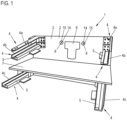
- Fig. 1 shows a supporting structure 1 as part of a wall-mounted sanitary furniture according to the invention.
- the support structure 1 comprises a support component 2 already mounted on the wall in the form of a larger support plate 3 and, in the exemplary embodiment shown, a total of six separate support elements 4, which are attached to the support plate 3, here screwed. All support elements 4 are designed identically, they are angle elements, which, depending on the intended use, are only attached to the carrier plate 3 in different rotational positions.
- the two upper support elements 4a serve, as will be discussed below, to hold a table top or, alternatively, directly a washbasin, while the other support elements 4b, which are arranged directly below the support elements 4a and the support elements 4c each accommodate a linear guide 5, on which each , which will be discussed below, corresponding drawers are arranged.
- the carrier plate 3 is provided with an appropriately sized opening 6 through which corresponding water supply and drainage lines are led to the attached washbasin.
- an intermediate plate 7 is arranged on the carrier plate 3, which, as will also be discussed below, serves to cover the lower drawer arranged on the carrier elements 4c.
- Fig. 1 shows the supporting structure 1 in the position fixed to the wall.
- two hanger screws 8 are provided on the wall side, as well as a straightening strip 9 is arranged on the wall side, which is aligned exactly horizontally and serves on the one hand to facilitate assembly, but on the other hand also to facilitate alignment of the supporting structure 1.
- the carrier plate 3 is, see the rear view Fig. 3 , on the one hand with two openings 10, through which the two hanger bolts 8 reach, and which are correspondingly oversized, so that a certain level of alignment is possible.
- a recess 11 is also provided on the back, which is designed as an elongated recess and is made by simply milling into the back of the support plate 3, which is made of wood. As will be described below, the shorter guide bar 9 reaches into this recess 11.
- Supporting structure 1 shown is pushed onto the hanger bolts 8, which is due to the oversizing of the Breakthroughs 10 are very easy.
- the carrier plate 3 is pushed against the wall and initially positioned in such a way that the guide bar 9 can engage in the recess 11.
- the support structure 1 can then be lowered slightly so that the upper edge 12 of the recess 11 rests on the upper edge 13 of the straightening bar 9. Since both edges 12, 13 are straight, the supporting structure 1 is aligned exactly horizontally. For alignment purposes, a slight horizontal displacement is still possible, as long as the openings 10 are oversized.
- a nut 14 and a washer 15 are screwed onto each hanger bolt 8, whereby the supporting structure 1 is finally secured.
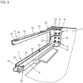
- Fig. 4 shows an enlarged view of the upper left area of the supporting structure 1 Fig. 1 with an enlarged view of the two support elements 4 and 4a, 4b there.
- Each carrier element 4 has a plate-shaped fastening section 16, which has corresponding openings through which corresponding fastening screws 17 engage for fastening to the carrier plate 3.
- a support arm 18 extends from the fastening section 16, each comprising a first leg 19 and a second leg 20, which run at right angles to one another and which (optionally) are connected to the respective fastening section 17 via correspondingly widened leg sections 21, 22.
- Each leg 19, 20 or leg section 21, 22 is provided with corresponding openings 23 through which fastening screws pass through for mounting the corresponding attachments.
- the two support elements 4a, 4b (the same applies to the support elements 4c) are identical.
- the support elements 4a and 4b are only arranged twisted by 90° to one another. This means that the leg 19 of the support element 4a is arranged horizontally at the top, while the leg 20 of the support element 4a projects vertically downwards. Since the support element 4b is rotated by 90 °, the leg 19 runs vertically upwards, while the leg 20 runs on the underside runs horizontally and can be seen carrying the linear guide 5.
- the two upper support elements 4a serve to hold a console-like table top or, alternatively, directly the washbasin itself, which means that these attachments rest on the legs 19 and, if provided, the leg sections 21 and are attached or screwed thereto.
- the drawer is arranged below it and guided over the linear guides 5 of the two support elements 4b.
- Fig. 5 shows a section of the arrangement Fig. 4 from the other side. Shown is a stiffening plate 24 which connects the two support elements 4a, 4b to one another. To serve this purpose, see Fig. 6 , corresponding fastening screws 25, via which the respective leg 20 of the carrier element 4a or 19 of the carrier element 4b is screwed to it. Additionally, but optionally, in the example shown, grooves 26 are provided on the stiffening plate 24, into which corresponding springs 27, which are arranged on the respective leg section 22 of the support element 4a or 21 of the support element 4b, engage. This provides further support and stiffening. As described, the grooves 26 and the tongues 27 are optional. If these are not provided, the support elements 4 or 4a, 4b, 4c are identical parts that are all identical. However, if springs are to be provided, these must be designed in the appropriate position, so that two different sets of support elements would have to be provided.
- the support elements 4 or 4a, 4b, 4c are preferably metal components that are made from a suitable metal sheet by forming. This makes it possible to dimension them accordingly narrow, that is to say that the respective support arms 18 and their legs 19, 20 can be made correspondingly narrow and delicate, but there is still sufficient mechanical stability to be able to support the corresponding attachments.
- the wide plate-shaped fastening sections 16 and the multiple screw connections already provide a sufficiently stable fixation on the table top 3, which, as in Fig. 3 indicated, corresponding Has openings for receiving the fastening screws.
- the stiffening plate 24 for example a wooden or plastic plate, which can also be screwed on the back from the table top side, additional stiffening is provided.
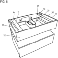
- Fig. 7 shows the support structure 1, with a drawer 8 being placed on the two lower support elements 4c or their linear guides 5 and attached thereto. As can be seen, the front of the drawer front forms the visible surface there, the two side walls of the drawer form the side visible surfaces.
- the intermediate plate 7 closes the drawer 28 flush on the top in the closed position.
- a cladding element 29, which sits on the intermediate plate 7, is already shown here for cladding the water inlet and outlet lines or pipes.
- an upper drawer 30 is placed on the linear guides 5 of the two support elements 4b and screwed to the linear guides 5.
- the drawer 30, like the drawer 28, has a base 31, a front wall 32 and two side walls 33, with the drawer 30 (the same applies to the drawer 28) with the base 31 sitting on the linear guides 5 and fastened thereto, in particular screwed or clipped.
- the linear guides 5 are therefore underfloor extensions.
- the height of the drawer 30 is dimensioned such that its upper edge ends marginally below the two legs 19, 20 of the two support elements 4a. A flush finish is also conceivable.
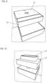
- a table top 34 is then placed on the two support elements 4a or their two upper legs 19, 20, the underside of which is slightly spaced from the upper edge of the drawer 30. If the drawer 30 ends slightly below the legs 19, 20, there is sufficient air. If it ends flush with the legs 19, 20, a corresponding mounting elevation must be provided on the underside of the table top 34, which is on the Thigh 19, 20 sits up. The sanitary furniture is fully assembled at the latest when the table top 34 is put on.
- the washbasin 35 is placed on the console-like table top 34 and connected in a corresponding manner so that the sanitary arrangement is completely assembled.
- the guide rails 4 are not identical parts, as in the example according to Figures 1 - 5 are shown.
- the legs 19, 20 are of different lengths, so that ultimately there are larger contact surfaces for the linear guides 5 or the table top 34 or, in the case of direct assembly, the washbasin 35.
- the intermediate plate 7 does not necessarily have to be provided.
- a corresponding free space is created between the two drawers 28, 30, with the intermediate plate 7 also serving as a storage area. If such a gap is not desired, it is easily possible to position the two lower support elements 4c higher, so that the lower drawer 28 is arranged immediately adjacent to the upper drawer 30.
Abstract
Wandhängend anzuordnendes Sanitärmöbel, umfassend- eine Tragkonstruktion (1) mit einem an einer vertikalen Wand zu befestigenden Trägerbauteil (2) und mehreren am Trägerbauteil (2) horizontal zueinander versetzt angeordneten, von diesem freitragend horizontal abragenden Trägerelementen (4, 4a, 4b, 4c), wobei an den oder an zumindest einem Teil der Trägerelemente (4, 4a, 4b, 4c) angeordnete Linearführungen (5) zur Aufnahme wenigstens einer ausziehbaren Schublade (28, 30) vorgesehen sind,- wenigstens eine Schublade (28,30) mit einem Boden (31), zwei Seitenwänden (33) und einer Frontwand (32), die auf die unterhalb des Bodens (31) angeordneten Linearführungen (5) aufgesetzt oder aufsetzbar ist,- wobei die oder zumindest ein Teil der Trägerelemente (4, 4a, 4b, 4c) entweder zur Aufnahme einer horizontal anzuordnenden Tischplatte (34) ausgelegt zur Aufnahme eines Waschtischs (35) oder unmittelbar zur Aufnahme eines Waschtischs (35) ausgeführt sind.Sanitary furniture to be mounted on a wall, comprising a support structure (1) with a support component (2) to be attached to a vertical wall and a plurality of support elements (4, 4a, 4b, 4c) arranged horizontally offset from one another on the support component (2) and projecting horizontally from the support component (4, 4a, 4b, 4c) , wherein linear guides (5) arranged on or on at least part of the support elements (4, 4a, 4b, 4c) are provided for receiving at least one pull-out drawer (28, 30), - at least one drawer (28, 30) with a Base (31), two side walls (33) and a front wall (32), which is placed or can be placed on the linear guides (5) arranged below the base (31), - the or at least part of the support elements (4, 4a, 4b, 4c) are either designed to hold a horizontally arranged table top (34) to hold a washstand (35) or are designed directly to hold a washstand (35).
Description
Ein solches Sanitärmöbel dient regelmäßig als Unterbaumöbel für einen Waschtisch, der auf das Sanitärmöbel aufgesetzt wird. Unterschieden wird zwischen Möbelwaschtischen, bei denen der auf das Sanitärmöbel aufgesetzte Waschtisch die komplette Oberseite der aus dem Sanitärmöbel und dem Waschtisch gebildeten Sanitäranordnung definiert, und Konsolenwaschtischen, bei denen das Sanitärmöbel eine Tischplatte umfasst, respektive eine solche aufgesetzt wird, auf die sodann der Waschtisch gesetzt wird, so dass die Oberseite des Möbels sowohl durch die Tischplatte als auch den Waschtisch gebildet wird.Such sanitary furniture regularly serves as a base unit for a washbasin that is placed on the sanitary furniture. A distinction is made between furniture washbasins, in which the washstand placed on the sanitary furniture defines the entire top of the sanitary arrangement formed by the sanitary furniture and the washstand, and console washbasins, in which the sanitary furniture includes a table top, or one is placed on which the washstand is then placed so that the top of the furniture is formed by both the table top and the vanity unit.
Neben der auf dem Boden stehenden Anordnung eines solchen Sanitärmöbels ist auch eine wandhängende Anordnung bekannt. Das Sanitärmöbel wird hierzu üblicherweise mit Montagewinkeln an der Wand befestigt. Hierzu wird zunächst ein erster Winkel an der Wand montiert, wonach ein entsprechender zweiter Winkel respektive ein Gegenstück an einem Korpus des Sanitärmöbels befestigt und eingehängt wird. Nachteilig bei dieser Art der hängenden Montage ist, dass diese bei breiten und großen Sanitärmöbeln unhandlich sein kann, da das Gewicht während des mitunter nicht allzu einfachen Einhängevorgangs der Montagewinkel gehalten werden muss.In addition to the floor-standing arrangement of such sanitary furniture, a wall-hung arrangement is also known. For this purpose, the sanitary furniture is usually attached to the wall using mounting brackets. For this purpose, a first angle is first mounted on the wall, after which a corresponding second angle or a counterpart is attached and hung on a body of the sanitary furniture. The disadvantage of this type of hanging installation is that it can be unwieldy with wide and large sanitary furniture, as the weight has to be supported during the sometimes not very easy hanging process of the mounting brackets.
Typischerweise bestehen Sanitärmöbel, wenn sie als Schubladenmöbel ausgeführt sind, aus einem Korpus, in dem die eine oder die mehren Schubladen auf Auszügen montiert sind. Eine Schublade ist entweder einschlagend, das heißt, dass die Schubladenfront sich komplett innerhalb des Korpus befindet und nicht aufträgt, oder sie ist aufschlagend, das heißt, dass die Schubladenfront vorderseitig auf dem Korpus aufsitzt. Die Montage einer solchen Schublade im Korpus hat den Nachteil, dass nicht die gesamte Möbelbreite genutzt werden kann, da vom nutzbaren Stauraum nicht nur die Breite der Schubladenzarge abgeht, sondern auch die Breite der Korpuswände.Sanitary furniture, when designed as drawer furniture, typically consists of a body in which one or more drawers are mounted on pull-outs. A drawer is either hinged, which means that the drawer front is completely inside the body and does not add any bulk, or it is hinged, which means that the drawer front sits on the front of the body. Installing such a drawer in the body has the disadvantage that the entire width of the furniture is not used because the usable storage space depends not only on the width of the drawer frame, but also on the width of the body walls.
Ein korpusloses Sanitärmöbel ist aus
Der Erfindung liegt das Problem zu Grunde, ein demgegenüber verbessertes Sanitärmöbel anzugeben.The invention is based on the problem of providing improved sanitary furniture.
Zur Lösung dieses Problems ist erfindungsgemäß ein wandhängend anzuordnendes Sanitärmöbel vorgesehen, umfassend
- eine Tragkonstruktion mit einem an einer vertikalen Wand zu befestigenden Trägerbauteil und mehreren am Trägerbauteil horizontal zueinander versetzt angeordneten, von diesem freitragend horizontal abragenden Trägerelementen, wobei an den oder an zumindest einem Teil der Trägerelemente angeordnete Linearführungen zur Aufnahme wenigstens einer ausziehbaren Schublade vorgesehen sind,
- wenigstens eine Schublade mit einem Boden, zwei Seitenwänden und einer Frontwand, die auf die unterhalb des Bodens angeordneten Linearführungen aufgesetzt oder aufsetzbar ist,
- wobei die oder zumindest ein Teil der Trägerelemente entweder zur Aufnahme einer horizontal anzuordnenden Tischplatte ausgelegt zur Aufnahme eines Waschtischs oder unmittelbar zur Aufnahme eines Waschtischs ausgeführt sind.
- a support structure with a support component to be attached to a vertical wall and a plurality of support elements arranged horizontally offset from one another on the support component and projecting horizontally from the support component, linear guides arranged on or on at least some of the support elements for receiving at least one pull-out drawer are provided,
- at least one drawer with a base, two side walls and a front wall, which is placed or can be placed on the linear guides arranged below the floor,
- wherein the or at least some of the support elements are designed either to hold a horizontally arranged table top to hold a washstand or directly to hold a washstand.
Das erfindungsgemäße, korpuslose und hängend anzuordnende Sanitärmöbel zeichnet sich durch eine sehr einfache Tragkonstruktion aus, die einerseits in der Lage ist, die wenigstens eine Schublade aufzunehmen und über Linearführungen zu führen, und die andererseits in der Lage ist, den Waschtisch selbst oder eine konsolenartige Tischplatte nebst Waschtisch aufzunehmen. Hierzu weist die Tragkonstruktion ein an einer benachbarten Gebäudewand anzuordnendes Trägerbauteil auf, bei dem es sich beispielsweise um eine Trägerplatte handeln kann, beispielsweise aus Holz oder auf Holzbasis oder aus Kunststoff oder dergleichen. Dieses eine, einfache Trägerbauteil wird wandseitig befestigt. An dem Trägerbauteil sind mindestens zwei Tragelemente angeordnet, gegebenenfalls auch mehr als zwei, wobei diese Tragelemente horizontal voneinander beabstandet sind, also beispielsweise im Bereich des rechten und linken Seitenrandes des Trägerbauteils angeordnet sind. Die Tragelemente, die beispielsweise als einfache Winkelelemente ausgeführt werden können, worauf nachfolgend noch eingegangen wird, erstrecken sich von dem Trägerbauteil, also beispielsweise der Trägerplatte horizontal nach vorne. An den Trägerelementen sind wenigstens zwei Linearführungen angeordnet, über die die wenigstens eine Schublade aufgenommen und geführt wird. Das heißt, dass die Trägerelemente einerseits der Aufnahme der Linearführung, andererseits aber auch dem Abstützen der Schublade dienen. Darüber hinaus sind die wenigstens zwei Trägerelemente oder, wenn mehr als zwei solcher Trägerelemente vorgesehen sind, ein Teil dieser Trägerelemente dazu eingerichtet, entweder unmittelbar den Waschtisch im Falle eines Möbelwaschtischs oder eine Tischplatte respektive eine Konsole und den Waschtisch im Falle eines Konsolenwaschtischs aufzunehmen. Das heißt, dass über die einfachen und entsprechend schmal dimensionierbaren, separaten Trägerelemente die entsprechenden Schnittstellen zur Verfügung gestellt werden, an denen einerseits die Schublade und andererseits der Waschtisch respektive die Tischplatte nebst Waschtisch aufgenommen werden.The sanitary furniture according to the invention, which has no body and can be arranged hanging, is characterized by a very simple supporting structure, which on the one hand is in the Is able to accommodate the at least one drawer and guide it via linear guides, and which, on the other hand, is able to accommodate the washstand itself or a console-like table top along with the washstand. For this purpose, the supporting structure has a support component to be arranged on an adjacent building wall, which can be, for example, a support plate, for example made of wood or based on wood or made of plastic or the like. This one, simple support component is attached to the wall. At least two support elements are arranged on the support component, possibly more than two, with these support elements being horizontally spaced apart from one another, for example in the area of the right and left side edges of the support component. The support elements, which can be designed, for example, as simple angle elements, which will be discussed below, extend horizontally forward from the support component, for example the support plate. At least two linear guides are arranged on the support elements, via which the at least one drawer is received and guided. This means that the support elements serve to hold the linear guide on the one hand, but also to support the drawer on the other hand. In addition, the at least two support elements or, if more than two such support elements are provided, a part of these support elements are designed to either directly accommodate the washstand in the case of a furniture washstand or a table top or a console and the washstand in the case of a console washstand. This means that the corresponding interfaces are provided via the simple and correspondingly narrow-sized, separate support elements, where on the one hand the drawer and on the other hand the washstand or the table top together with the washstand are accommodated.
Hieraus ergibt sich demzufolge eine sehr einfache und eher filigrane, nach vorne sehr wenig Raum einnehmende Tragkonstruktion, da die separaten Trägerelemente wie beschrieben entsprechend schmal, sowohl in horizontaler als auch vertikaler Richtung, dimensioniert werden können. Bevorzugt sind diese Trägerelemente einfache Metallbauteile, die bereits von Haus aus auch eine hinreichende Stabilität aufweisen, um die entsprechenden Gewichte von Schublade, Waschtisch etc. aufnehmen und abstützen zu können. Insbesondere eine Metallausführung erlaubt eine besonders schmale Auslegung dieser Trägerelemente.This results in a very simple and rather delicate support structure that takes up very little space at the front, since the separate support elements can be dimensioned to be correspondingly narrow, both in the horizontal and vertical directions, as described. These support elements are preferably simple metal components that inherently have sufficient stability to support the corresponding weights To be able to hold and support drawers, washbasins etc. In particular, a metal design allows these support elements to be particularly narrow.
Da die Tragkonstruktion entsprechend kleinbauend respektive wenig Raum einnehmend ausgeführt ist, steht vor dem Trägerbauteil und damit unterhalb des Waschtischs hinreichend viel Raum zur Verfügung, der bestmöglich über die wenigstens eine Schublade oder die mehreren Schubladen genutzt werden kann. Da das erfindungsgemäße Sanitärmöbel korpuslos ist, bilden demzufolge die Schubladenfront sowie die Schubladenseiten die entsprechenden Sichtflächen, definieren also das Äußere des Sanitärmöbels nach vorne und zu den Seiten hin. Demzufolge handelt es sich bei den Linearführungen, auf die der Boden der Schublade aufgesetzt wird, um entsprechende Unterflurauszüge, die ebenfalls entsprechend schmal dimensioniert werden können und nicht sichtbar sind.Since the support structure is designed to be small or take up little space, there is enough space available in front of the support component and therefore below the washbasin, which can be used as best as possible via at least one drawer or the several drawers. Since the sanitary furniture according to the invention has no body, the drawer front and the drawer sides therefore form the corresponding visible surfaces, i.e. define the exterior of the sanitary furniture to the front and to the sides. As a result, the linear guides on which the bottom of the drawer is placed are corresponding underfloor pull-outs, which can also be dimensioned accordingly narrow and are not visible.
Zur einfachen Montage können am Trägerbauteil wenigstens zwei Durchbrechungen zur Aufnahme von wandseitig zu befestigenden Stockschrauben vorgesehen sein. Diese Art der Befestigung des Trägerbauteils, also beispielsweise der Trägerplatte, ist sehr einfach. Es sind lediglich wandseitig in entsprechenden Bohrungen wenigstens zwei Stockschrauben einzuschrauben, die durch die entsprechenden trägerbauteilseitigen Durchbrechungen geführt werden, wonach zur Befestigung entsprechende Muttern auf die Stockschrauben geschraubt werden. Bevorzugt sind die Durchbrechungen mit Übermaß ausgeführt, sodass eine Ausrichtung des Trägerbauteils vor dem finalen Festschrauben möglich ist. Insbesondere sollte eine seitliche Ausrichtung möglich sein, wozu die Durchbrechungen bevorzugt als Langlöcher ausgeführt sind, die aber auch in vertikaler Richtung ein leichtes Übermaß haben können.For easy assembly, at least two openings can be provided on the support component to accommodate hanger bolts to be fastened to the wall. This type of attachment of the carrier component, for example the carrier plate, is very simple. All you have to do is screw at least two hanger bolts into corresponding holes on the wall side, which are guided through the corresponding openings on the support component side, after which appropriate nuts are screwed onto the hanger bolts for fastening. The openings are preferably oversized so that the support component can be aligned before the final screwing. In particular, a lateral orientation should be possible, for which the openings are preferably designed as elongated holes, but which can also have a slight oversize in the vertical direction.
Das Trägerbauteil kann beispielsweise als Metallschiene ausgeführt sein, an der die entsprechenden Trägerelemente angeordnet werden, wobei diese Metallschiene auch vertikale Verlängerungsabschnitte aufweisen kann, wenn vertikal versetzt mehrere Trägerelemente zur Aufnahme von beispielsweise zwei Schubläden anzuordnen sind. Bei dieser Ausgestaltung ist aufgrund der schienenartigen Auslegung keine Vorkehrung zu treffen, um die Wasserzulauf- und -ablaufleitung zur Wand hin zu führen. Alternativ kann auch eine entsprechende Trägerplatte verwendet werden, die bevorzugt rechtwinkliger Form ist und entsprechend dimensioniert werden kann, je nachdem, ob eine oder beispielsweise zwei Schubladen vorzusehen sind. Da es sich um ein plattenförmiges Teil handelt, ist in diesem Fall auch eine entsprechende Durchbrechung zur Durchführung der Wasserzulauf- und -ablaufleitung vorzusehen.The support component can, for example, be designed as a metal rail on which the corresponding support elements are arranged, this metal rail can also have vertical extension sections if several support elements are to be arranged vertically offset to accommodate, for example, two drawers. In this configuration, due to the With a rail-like design, no provision is made to guide the water inlet and outlet pipes towards the wall. Alternatively, a corresponding support plate can also be used, which is preferably rectangular in shape and can be dimensioned accordingly, depending on whether one or, for example, two drawers are to be provided. Since it is a plate-shaped part, in this case a corresponding opening must also be provided for the passage of the water inlet and outlet pipe.
Um die wandseitige Montage der Tragkonstruktion möglichst einfach zu gestalten, wie auch die horizontale Ausrichtung, sieht eine besonders zweckmäßige Weiterbildung der Erfindung vor, dass bei Ausführung des Trägerbauteils als Trägerplatte an der Trägerplatte eine sich bezogen auf die Montagestellung horizontal erstreckende, längliche Durchbrechung oder Vertiefung zur Aufnahme einer wandseitig zu befestigende Richtleiste, auf der die Trägerplatte in der Montagestellung aufsitzt, vorgesehen ist. Das Montageset respektive das Sanitärmöbel umfasst auch eine Richtleiste, die wandseitig mittels geeigneter Befestigungsschrauben fixiert wird. Sie wird so befestigt, dass sie ideal horizontal verläuft. Soll nun die Tragkonstruktion montiert, so ist diese anzuheben und kann unter Eingriff der Richtleiste in die Durchbrechung oder Vertiefung auf diese aufgesetzt werden. Die Richtleiste stützt demzufolge im Rahmen der folgenden Ausrichtung und Montage, im Rahmen derer die Muttern auf die Stockschrauben geschraubt werden etc., das Gewicht der Tragkonstruktion ab, dieses ist also nicht dauerhaft zu halten. Darüber hinaus ist, nachdem die Richtleiste genau horizontal ausgerichtet ist, hierüber auch sichergestellt, dass die Tragkonstruktion exakt horizontal ausgerichtet ist, sodass auch diesbezüglich keinerlei Arbeiten erforderlich sind. Lediglich eine Seitenausrichtung kann nötig sein, was durch einfaches seitliches Verschieben auf der Richtleiste möglich ist.In order to make the wall-side assembly of the supporting structure as simple as possible, as well as the horizontal alignment, a particularly useful development of the invention provides that when the carrier component is designed as a carrier plate, an elongated opening or recess that extends horizontally in relation to the assembly position is provided on the carrier plate Accommodation of a guide bar to be attached to the wall, on which the carrier plate sits in the assembly position, is provided. The assembly set or the sanitary furniture also includes a guide bar that is fixed on the wall using suitable fastening screws. It is attached so that it runs ideally horizontally. If the supporting structure is now to be installed, it must be lifted and placed on top of the opening or recess by engaging the guide bar. The guide bar therefore supports the weight of the supporting structure during the subsequent alignment and assembly, during which the nuts are screwed onto the hanger bolts, etc., so this cannot be maintained permanently. In addition, once the guide bar is aligned exactly horizontally, this also ensures that the supporting structure is aligned exactly horizontally, so that no work is required in this regard. Only side alignment may be necessary, which is possible by simply moving it sideways on the alignment bar.
Ein zentrales Merkmal der Tragkonstruktion sind die Trägerelemente, die die Linearführungen und die Schublade respektive den Waschtisch tragen bzw. abstützen. Sie sind wie ausgeführt möglichst schmal auszuführen, sodass sie, nachdem sie sich horizontal nach vorne erstrecken, möglichst wenig Raum einnehmen. Um dies zu ermöglichen, kann erfindungsgemäß jedes Trägerbauteil einen plattenförmigen Befestigungsabschnitt zur Verbindung mit dem Trägerbauteil sowie einen vom Befestigungsabschnitt rechtwinklig abragenden Tragarm zur Aufnahme einer Linearführung oder der Tischplatte oder des Waschtischs aufweisen. Über die Befestigungsplatte wird eine entsprechend flächig dimensionierte Befestigungsschnittstelle zum Verbinden jedes Trägerelements mit dem Trägerbauteil, also beispielsweise der Trägerplatte, bereitgestellt. Dieser plattenförmige Befestigungsabschnitt kann mehrere Durchbrechungen zur Aufnahme von geeigneten Verbindungsschrauben, mit denen das Trägerelement an dem Trägerbauteil verschraubt wird, aufweisen. Gleichzeitig bietet die plattenförmige Ausgestaltung eine entsprechend große Abstützfläche, sodass die aufzunehmenden Teile hinreichend abgestützt sind und ein Verkippen ausgeschlossen ist. Von dem Befestigungsabschnitt ragt ein entsprechender Tragarm rechtwinklig ab, wobei dieser Tragarm zur Aufnahme der Linearführungen respektive der Tischplatte oder des Waschtischs, je nachdem wozu das Trägerelement konkret dient, ausgelegt ist. Wie ausgeführt kann dieser Tragarm möglichst schmal ausgelegt werden, insbesondere wenn das Trägerelement aus Metall ist, sodass er wenig Raum benötigt.A central feature of the supporting structure are the support elements that carry or support the linear guides and the drawer or the washbasin. As stated, they should be made as narrow as possible so that they take up as little space as possible after they extend horizontally forward take in. To make this possible, according to the invention each support component can have a plate-shaped fastening section for connection to the support component and a support arm projecting at right angles from the fastening section for receiving a linear guide or the table top or the washbasin. A correspondingly flat-sized fastening interface for connecting each carrier element to the carrier component, for example the carrier plate, is provided via the fastening plate. This plate-shaped fastening section can have several openings for receiving suitable connecting screws with which the carrier element is screwed to the carrier component. At the same time, the plate-shaped design offers a correspondingly large support surface, so that the parts to be picked up are adequately supported and tilting is prevented. A corresponding support arm projects at right angles from the fastening section, this support arm being designed to accommodate the linear guides or the table top or the washbasin, depending on what the support element is specifically used for. As stated, this support arm can be designed to be as narrow as possible, especially if the support element is made of metal, so that it requires little space.
Dabei ist in Weiterbildung der Erfindung der jeweilige Tragarm bevorzugt im Querschnitt L-förmig ausgeführt. Er weist folglich zwei entsprechende Armschenkel auf, die rechtwinklig zueinander verlaufen und beispielsweise gleiche Breite aufweisen können. Diese Ausgestaltung ist dahingehend von besonderem Vorteil, als ein solches Trägerbauteil zu unterschiedlichen Zwecken verwendet werden kann. Soll das Trägerbauteil der Aufnahme von Linearführungen dienen, so kann es derart angeordnet werden, dass der eine Armschenkel horizontal verläuft, während der andere Armschenkel nach oben vertikal verläuft. Auf den horizontalen Armschenkel wird eine Linearführung gesetzt, der vertikale Armschenkel verläuft unmittelbar unterhalb des Schubladenbodens. Soll das Trägerelement zur Aufnahme des Waschtischs oder Tischplatte dienen, so wird das identische Trägerelement in um 90° gedrehter Position montiert. In diesem Fall verläuft der eine Tragarmschenkel horizontal, er bildet die Oberseite, während der andere Armschenkel vertikal nach unten abragt. Die Tischplatte oder der Waschtisch kann auf den oberen Tragschenkel, der die Befestigungsebene zusammen mit dem horizontal versetzten zweiten Trägerelement bildet, aufgesetzt und daran verschraubt werden. Das heißt, dass in diesem Fall bezüglich der Trägerelemente ausschließlich Gleichteile zum Einsatz kommen, was die Ausgestaltung der Tragkonstruktion noch weiter vereinfacht. Alternativ kann auch ein Schenkel breiter als der andere sein, wobei in diesem Fall keine Gleichteile verwendet werden, sondern sich Tragelemente, die die Tischplatte oder den Waschtisch tragen, von den Tragelementen, die die Linearführungen tragen, etwas unterscheiden.In a further development of the invention, the respective support arm is preferably L-shaped in cross section. It therefore has two corresponding arm legs, which run at right angles to one another and can, for example, have the same width. This configuration is particularly advantageous in that such a carrier component can be used for different purposes. If the support component is intended to accommodate linear guides, it can be arranged in such a way that one arm leg runs horizontally, while the other arm leg runs vertically upwards. A linear guide is placed on the horizontal arm leg, the vertical arm leg runs directly below the drawer base. If the support element is intended to hold the washbasin or table top, the identical support element is mounted in a position rotated by 90°. In this case, one arm leg runs horizontally, forming the top, while the other arm leg projects vertically downwards. The table top or the Washbasin can be placed on the upper support leg, which forms the fastening level together with the horizontally offset second support element, and screwed to it. This means that in this case only identical parts are used with regard to the support elements, which further simplifies the design of the support structure. Alternatively, one leg can also be wider than the other, in which case no identical parts are used, but rather the support elements that carry the table top or the washstand are slightly different from the support elements that carry the linear guides.
Die Tragarmschenkel sind natürlich mit entsprechenden Durchbrechungen versehen, seien es Bohrungen oder Langlöcher oder Ähnliches, die es ermöglichen, eine Linearführung oder die Tischplatte respektive den Waschtisch entsprechend zu verschrauben. Besonders bevorzugt ist wie ausgeführt die Ausführung jedes dieser Trägerelemente respektive Winkelelemente, seinen es Gleichteile oder unterschiedliche Teile, aus Metall respektive Metallblech, was eine besonders schmale Ausgestaltung ermöglicht, die jedoch gleichzeitig die entsprechenden mechanischen Eigenschaften zur Verfügung stellt.The support arm legs are of course provided with appropriate openings, be they bores or elongated holes or something similar, which make it possible to screw a linear guide or the table top or the washbasin accordingly. As stated, it is particularly preferred to design each of these support elements or angle elements, whether they are identical parts or different parts, made of metal or sheet metal, which enables a particularly narrow design, but at the same time provides the corresponding mechanical properties.
In einer konkreten Anordnungsausgestaltung der Trägerelemente ist es denkbar, im oberen Bereich des Trägerbauteils an beiden Seiten des Trägerbauteils jeweils zwei Trägerelemente anzuordnen, wobei am unteren Trägerelement eine Linearführung angeordnet ist und das obere Trägerelement der Aufnahme der Tischplatte oder des Waschtischs dient. Es kommen also im Bereich des rechten und linken Trägerbauteil- oder Trägerplattenrandes jeweils ein paar von Trägerelementen zum Einsatz, bevorzugt wie beschreiben als Gleichbauteile in Form der Winkelelemente. Dabei dienen die beiden jeweils oberen Träger- oder Winkelelemente der Aufnahme des Waschtischs oder der Tischplatte, während die beiden unteren der Aufnahme der Linearführungen für die Schublade dienen. Dabei sind, sofern alle Trägerelemente wie beschrieben bevorzugt identisch ausgeführt sind, jeweils übereinander angeordnete Trägerelemente um 90° verdreht zueinander angeordnet, sodass sich die entsprechende Schenkelausrichtung ergibt.In a specific arrangement design of the support elements, it is conceivable to arrange two support elements in the upper region of the support component on both sides of the support component, with a linear guide being arranged on the lower support element and the upper support element serving to hold the table top or the washbasin. So in the area of the right and left edge of the support component or support plate, a few support elements are used, preferably as described as identical components in the form of the angle elements. The two upper support or angle elements serve to hold the washbasin or table top, while the two lower ones serve to hold the linear guides for the drawer. In this case, provided that all carrier elements are preferably designed identically as described, carrier elements arranged one above the other are arranged rotated by 90° to one another, so that the corresponding leg alignment results.
Um die Anordnung der jeweiligen, übereinander angeordneten Trägerelemente eines jeden Trägerpaares noch weiter auszusteifen, sieht eine zweckmäßige Weiterbildung der Erfindung vor, dass zusätzlich zur Befestigung respektive Verschraubung am Trägerbauteil respektive der Trägerplatte auch ein Versteifungselement, das beide übereinander angeordneten Trägerelemente verbindet, vorgesehen ist. Über dieses Versteifungselement werden letztlich die beiden Tragarme miteinander verbunden, sodass auch hierüber eine Vertikalabstützung realisiert wird. Dabei kann es sich bei dem Versteifungselement um eine an beiden Trägerelementen mittels geeigneter Befestigungselemente befestigte oder befestigbare Verbindungsplatte handeln, beispielsweise eine angeschraubte Metall-, Holz- oder Kunststoffplatte. Alternativ hierzu kann diese Verbindungsplatte auch stoffschlüssig an den Trägerelementen befestigt werden, wobei es sich, nachdem die Trägerelemente bevorzugt aus Metall sind, auch bei der Verbindungsplatte um eine Metallplatte, die angeschweißt ist, handeln kann. Diese Schweißanordnung kann bereits im Vorfeld erwirkt werden, das heißt, dass das Trägerelementpaar von Haus aus über die Verbindungsplatte verfügt. Auch ein Ankleben ist alternativ denkbar.In order to further stiffen the arrangement of the respective carrier elements of each pair of carriers arranged one above the other, an expedient development of the invention provides that, in addition to the fastening or screwing on the carrier component or the carrier plate, a stiffening element is also provided, which connects both carrier elements arranged one above the other. The two support arms are ultimately connected to one another via this stiffening element, so that vertical support is also achieved here. The stiffening element can be a connecting plate that is fastened or can be fastened to both support elements by means of suitable fastening elements, for example a screwed-on metal, wood or plastic plate. Alternatively, this connecting plate can also be attached to the support elements in a materially bonded manner, whereby, since the support elements are preferably made of metal, the connecting plate can also be a metal plate that is welded on. This welding arrangement can be achieved in advance, which means that the pair of support elements inherently has the connecting plate. Gluing is also conceivable as an alternative.
Ist eine lösbare Verbindungsplatte vorgesehen, so kann zur zusätzlichen Versteifung vorgesehen sein, dass die lösbar befestigte oder befestigbare Versteifungsplatte an den beiden Trägerelementen zugeordnete Nuten aufweist, in die an den Trägerelementen abragende Federn eingreifen. Es wird zusätzlich eine Formschlussverbindung über diesen Nut-Federeingriff realisiert, der eine weitere Abstützebene bildet. Die Federn der Trägerelemente, die an dem jeweiligen Tragschenkel zur Seite abragen, können im Rahmen der Herstellung durch geeignete Umformung ausgebildet werden, wohingegen die Nuten auf einfache Weise eingefräst werden. Nach der Montage der Trägerelemente ist es lediglich noch erforderlich, die Versteifungsplatte seitlich anzuordnen, mit den Nuten auf die Federn aufzustecken und final zu verschrauben.If a releasable connecting plate is provided, it can be provided for additional stiffening that the releasably fastened or fastenable stiffening plate has grooves assigned to the two support elements, into which springs protruding from the support elements engage. In addition, a positive connection is realized via this tongue-and-groove engagement, which forms a further support level. The springs of the support elements, which protrude to the side on the respective support leg, can be formed during production by suitable forming, whereas the grooves are milled in a simple manner. After assembling the support elements, it is only necessary to arrange the stiffening plate laterally, attach it to the tongues using the grooves and finally screw it together.
Werden, wie erfindungsgemäß ferner vorgesehen, am Trägerbauteil wenigstens zwei Paare an Trägerelementen, die mit Linearführungen versehen sind, in unterschiedlichen Horizontalebenen angeordnet, kann jedes Paar an Trägerelementen jeweils eine Schublade aufnehmen, das heißt, dass bei dieser Ausgestaltung zwei übereinander angeordnete Schubladen vorgesehen sind. Beide Schubladen weisen jeweils einen Boden, ein Frontteil sowie Seitenteile auf, wobei die Front- und Seitenteilflächen jeweils das Möbeläußere bilden. Da die beiden unteren Trägerelemente letztlich in einem beliebigen Abstand zu den beiden oberen Trägerelementen an dem Trägerbauteil respektive der Trägerplatte befestigt werden können, kann demzufolge ihr Abstand und hierüber auch die Höhe der zweiten Schublade entsprechend variiert werden. Beide Schubladen können gleich groß sein, die untere Schublade kann aber auch niedriger oder höher als die obere Schublade sein.If, as further provided according to the invention, at least two pairs of carrier elements, which are provided with linear guides, are installed on the carrier component Arranged on different horizontal planes, each pair of support elements can accommodate one drawer, which means that in this embodiment two drawers arranged one above the other are provided. Both drawers each have a base, a front part and side parts, with the front and side part surfaces each forming the outside of the furniture. Since the two lower support elements can ultimately be attached to the support component or the support plate at any distance from the two upper support elements, their distance and therefore also the height of the second drawer can be varied accordingly. Both drawers can be the same size, but the bottom drawer can also be lower or higher than the top drawer.
Diese Abstandsvariationsmöglichkeit erlaubt es auch, zwischen den beiden Schubladen einen Freiraum zu lassen. Um die untere Schublade letztlich in der Schließstellung oberseitig abzudecken, sieht eine zweckmäßige Weiterbildung der Erfindung vor, an dem Trägerbauteil wenigstens eine sich horizontal davon erstreckende Zwischenplatte, die zwischen den wenigstens zwei Schubladen angeordnet ist, vorzusehen. Diese Zwischenplatte befindet sich unmittelbar oberhalb der unteren Schublade, deckt diese also in der Schließstellung ab. Gleichzeitig kann sie auch als Ablageplatte für Gegenstände dienen. Auf dieser Zwischenplatte kann natürlich verzichtet werden, wenn beide Schubladen quasi unmittelbar vertikal aneinander anschließen.This distance variation option also allows you to leave space between the two drawers. In order to ultimately cover the top of the lower drawer in the closed position, an expedient development of the invention provides for at least one intermediate plate to be provided on the support component, which extends horizontally therefrom and is arranged between the at least two drawers. This intermediate plate is located directly above the lower drawer and therefore covers it in the closed position. At the same time, it can also serve as a storage shelf for items. This intermediate plate can of course be dispensed with if both drawers are almost directly connected vertically to one another.
Neben dem Sanitärmöbel selbst betrifft die Erfindung ferner eine Sanitäranordnung, umfassend ein vorstehend beschriebenes Sanitärmöbel sowie einen direkt auf zwei Trägerelementen anzuordnenden Waschtisch oder eine auf zwei Trägerelementen anzuordnende Tischplatte sowie einen auf der Tischplatte anzuordnenden Waschtisch.In addition to the sanitary furniture itself, the invention also relates to a sanitary arrangement, comprising a sanitary furniture described above and a washbasin to be arranged directly on two support elements or a table top to be arranged on two support elements and a washstand to be arranged on the table top.
Weitere Vorteile und Einzelheiten der vorliegenden Erfindung ergeben sich aus den im Folgenden beschriebenen Ausführungsbeispielen sowie anhand der Zeichnungen. Dabei zeigen:
- Fig. 1
- eine perspektivische Prinzipdarstellung einer Tragkonstruktion eines erfindungsgemäßen Sanitärmöbels in wandhängender Anordnung,
- Fig. 2
- eine Ansicht der Wand vor der Anordnung der Tragkonstruktion mit daran angeordneten Stockschrauben und Richtleiste,
- Fig. 3
- eine Rückseitenansicht der Trägerplatte der Tragkonstruktion aus
Fig. 1 , - Fig. 4
- eine vergrößerte Teilansicht der Tragkonstruktion aus
Fig. 1 unter Darstellung zweier Trägerelemente, - Fig. 5
- die Anordnung aus
Fig. 4 in perspektivischer Ansicht von der anderen Seite, - Fig. 6
- eine vergrößerte Teilansicht zweier Trägerelemente mit diese verbindender Versteifungsplatte,
- Fig. 7
- die Tragkonstruktion aus
Fig. 1 mit eingesetzter unterer Schublade, - Fig. 8
- die Anordnung aus
Fig. 7 mit eingesetzter oberer Schublade, - Fig. 9
- die Anordnung aus
Fig. 8 mit auf die oberen Trägerelemente aufgesetzter Tischplatte, und - Fig. 10
- eine erfindungsgemäße Sanitäranordnung umfassend ein erfindungsgemäßes Sanitärmöbel sowie einen aufgesetzten Waschtisch.
- Fig. 1
- a perspective schematic representation of a supporting structure of a sanitary furniture according to the invention in a wall-hung arrangement,
- Fig. 2
- a view of the wall before the support structure is arranged with the hanger screws and guide bar arranged on it,
- Fig. 3
- a rear view of the support plate of the supporting structure
Fig. 1 , - Fig. 4
- an enlarged partial view of the supporting structure
Fig. 1 showing two support elements, - Fig. 5
- the arrangement
Fig. 4 in perspective view from the other side, - Fig. 6
- an enlarged partial view of two support elements with a stiffening plate connecting them,
- Fig. 7
- the supporting structure
Fig. 1 with inserted bottom drawer, - Fig. 8
- the arrangement
Fig. 7 with inserted top drawer, - Fig. 9
- the arrangement
Fig. 8 with a table top placed on the upper support elements, and - Fig. 10
- a sanitary arrangement according to the invention comprising a sanitary furniture according to the invention and an attached washbasin.
Des Weiteren ist die Trägerplatte 3 mit einer entsprechend dimensionierten Durchbrechung 6 versehen, durch die entsprechende Wasserzu- und -ableitungen zum aufgesetzten Waschtisch geführt werden. Schließlich ist an der Trägerplatte 3 eine Zwischenplatte 7 angeordnet, die, worauf ebenfalls nachfolgend eingegangen wird, der Abdeckung der unteren, an den Trägerelementen 4c angeordneten Schublade dient.Furthermore, the
Die Trägerplatte 3 ist, siehe die Rückseitenansicht aus
Zur Montage wird nun die in
Wie
Die Trägerelemente 4 bzw. 4a, 4b, 4c sind vorzugsweise Metallbauteile, die aus einem geeignetem Metallblech durch Umformen hergestellt sind. Dies ermöglicht es, sie entsprechend schmal dimensionieren zu können, das heißt, dass die jeweiligen Tragarme 18 und deren Schenkel 19, 20 entsprechend schmal und filigran ausgeführt werden können, gleichwohl ist dennoch eine hinreichende mechanische Stabilität gegeben, um die entsprechenden Anbauteile abstützen zu können. Über die breiten plattenförmigen Befestigungsabschnitte 16 sowie die Mehrfachverschraubung ist bereits eine hinreichend stabile Fixierung an der Tischplatte 3 gegeben, die hierzu, wie in
Anschließend wird, siehe
Die Höhe der Schublade 30 ist so bemessen, dass sie mit ihrem oberen Rand marginal unterhalb der beiden Schenkel 19, 20 der beiden Tragelemente 4a endet. Auch ein bündiger Abschluss ist denkbar.The height of the
Wie
Sodann ist lediglich noch, siehe
Beim gezeigten Ausführungsbeispiel der
Anstelle der in den
Und schließlich ist festzuhalten, dass die Zwischenplatte 7 nicht zwingend vorzusehen ist. Im gezeigten Beispiel wird hierüber ein entsprechender Freiraum zwischen den beiden Schubladen 28, 30 erzeugt, wobei die Zwischenplatte 7 auch als Ablagefläche dient. Ist ein solcher Zwischenraum nicht gewünscht, so ist es problemlos möglich, die beiden unteren Trägerelemente 4c höher zu positionieren, sodass die untere Schublade 28 unmittelbar anschließend an die obere Schublade 30 angeordnet ist.And finally it should be noted that the
Claims (14)
Applications Claiming Priority (1)
| Application Number | Priority Date | Filing Date | Title |
|---|---|---|---|
| DE102022122602.6A DE102022122602A1 (en) | 2022-09-06 | 2022-09-06 | Wall-mounted sanitary furniture |
Publications (1)
| Publication Number | Publication Date |
|---|---|
| EP4335323A1 true EP4335323A1 (en) | 2024-03-13 |
Family
ID=87567209
Family Applications (1)
| Application Number | Title | Priority Date | Filing Date |
|---|---|---|---|
| EP23190371.7A Pending EP4335323A1 (en) | 2022-09-06 | 2023-08-08 | Sanitary furniture to be mounted on a wall |
Country Status (4)
| Country | Link |
|---|---|
| US (1) | US20240076864A1 (en) |
| EP (1) | EP4335323A1 (en) |
| CA (1) | CA3211157A1 (en) |
| DE (1) | DE102022122602A1 (en) |
Citations (2)
| Publication number | Priority date | Publication date | Assignee | Title |
|---|---|---|---|---|
| CN208693108U (en) * | 2018-04-18 | 2019-04-05 | 佛山市顺德区澳景斯家具卫浴有限公司 | A kind of Multifunctional bathroom cabinet |
| DE102019114279A1 (en) | 2019-05-28 | 2020-12-03 | Duravit Aktiengesellschaft | Sanitary facility |
Family Cites Families (2)
| Publication number | Priority date | Publication date | Assignee | Title |
|---|---|---|---|---|
| DE102006029801A1 (en) | 2006-06-27 | 2008-01-03 | Kludi Gmbh & Co. Kg | Angular wash stand console, has carrier frame exhibiting four support rods each having attachment points for attachment parts that are inserted from frame inner side, where attachment points are spaced from each other with specific distance |
| DE202017004626U1 (en) | 2017-09-05 | 2017-09-14 | Burgbad Ag | Module system and module base and module unit for such a system |
-
2022
- 2022-09-06 DE DE102022122602.6A patent/DE102022122602A1/en active Pending
-
2023
- 2023-08-08 EP EP23190371.7A patent/EP4335323A1/en active Pending
- 2023-08-29 US US18/239,420 patent/US20240076864A1/en active Pending
- 2023-09-05 CA CA3211157A patent/CA3211157A1/en active Pending
Patent Citations (3)
| Publication number | Priority date | Publication date | Assignee | Title |
|---|---|---|---|---|
| CN208693108U (en) * | 2018-04-18 | 2019-04-05 | 佛山市顺德区澳景斯家具卫浴有限公司 | A kind of Multifunctional bathroom cabinet |
| DE102019114279A1 (en) | 2019-05-28 | 2020-12-03 | Duravit Aktiengesellschaft | Sanitary facility |
| US11268269B2 (en) * | 2019-05-28 | 2022-03-08 | Duravit Aktiengesellschaft | Sanitary installation |
Also Published As
| Publication number | Publication date |
|---|---|
| US20240076864A1 (en) | 2024-03-07 |
| CA3211157A1 (en) | 2024-03-06 |
| DE102022122602A1 (en) | 2024-03-07 |
Similar Documents
| Publication | Publication Date | Title |
|---|---|---|
| EP0917266B1 (en) | Mounting device | |
| EP1003401B1 (en) | Twinned kitchen furniture system, in particular to be wall-mounted with or without bottom support | |
| AT401851B (en) | FITTING | |
| EP1458264A1 (en) | Fixing element for fixing a household appliance | |
| EP2801291A1 (en) | Furniture fitting to form a pull-out waste collection device | |
| EP4335323A1 (en) | Sanitary furniture to be mounted on a wall | |
| WO2021105197A1 (en) | Furniture kit | |
| DE102005028740B4 (en) | Kitchen Furniture System | |
| AT399086B (en) | Adjustable fascia panel for drawer fronts - is fixed by screw-on angled plate with infinitely adjustable angle | |
| DE3125099C2 (en) | Convertible piece of furniture | |
| EP2712516A2 (en) | Lifting system for a vertically adjustable workstation system and workplace system with such a lifting system | |
| DE202004008478U1 (en) | Furniture cupboard or shelving has several individual elements connectable in various combinations through insert pins engaging in side walls to prevent cross sliding | |
| DE102021109616B4 (en) | Variable furniture element and modular furniture system made up of several furniture elements | |
| DE102011015494B4 (en) | mounting arrangement | |
| EP1366691B1 (en) | Kitchen furniture system | |
| EP3760080A1 (en) | Mounting system for furniture | |
| EP3824760A2 (en) | Furniture | |
| DE3011843A1 (en) | Support connector for furniture panels - has portion fitting bore in vertical panel and pivoted end(s) fitting recesses in horizontal panels | |
| WO2024032857A1 (en) | Installation element and installation system | |
| DE202019106201U1 (en) | cabinet | |
| DE3025956C2 (en) | Extending table for furniture, in particular kitchen furniture | |
| DE19940168C2 (en) | Plate element made of sheet metal | |
| EP2227985A1 (en) | Cabinet element, in particular drawer | |
| EP3616563A1 (en) | Cupboard | |
| DE4012835A1 (en) | Box-shaped furniture such as cupboard - has sides, base panel, and plinth frame with side and transverse struts, and covering struts |
Legal Events
| Date | Code | Title | Description |
|---|---|---|---|
| PUAI | Public reference made under article 153(3) epc to a published international application that has entered the european phase |
Free format text: ORIGINAL CODE: 0009012 |
|
| STAA | Information on the status of an ep patent application or granted ep patent |
Free format text: STATUS: THE APPLICATION HAS BEEN PUBLISHED |
|
| AK | Designated contracting states |
Kind code of ref document: A1 Designated state(s): AL AT BE BG CH CY CZ DE DK EE ES FI FR GB GR HR HU IE IS IT LI LT LU LV MC ME MK MT NL NO PL PT RO RS SE SI SK SM TR |