EP1517625B1 - Height adjustable working table - Google Patents
Height adjustable working table Download PDFInfo
- Publication number
- EP1517625B1 EP1517625B1 EP03712042A EP03712042A EP1517625B1 EP 1517625 B1 EP1517625 B1 EP 1517625B1 EP 03712042 A EP03712042 A EP 03712042A EP 03712042 A EP03712042 A EP 03712042A EP 1517625 B1 EP1517625 B1 EP 1517625B1
- Authority
- EP
- European Patent Office
- Prior art keywords
- work table
- set forth
- worktop
- guide rails
- work
- Prior art date
- Legal status (The legal status is an assumption and is not a legal conclusion. Google has not performed a legal analysis and makes no representation as to the accuracy of the status listed.)
- Expired - Lifetime
Links
Images


Classifications
-
- A—HUMAN NECESSITIES
- A47—FURNITURE; DOMESTIC ARTICLES OR APPLIANCES; COFFEE MILLS; SPICE MILLS; SUCTION CLEANERS IN GENERAL
- A47B—TABLES; DESKS; OFFICE FURNITURE; CABINETS; DRAWERS; GENERAL DETAILS OF FURNITURE
- A47B17/00—Writing-tables
- A47B17/003—Writing-tables made of metal
-
- A—HUMAN NECESSITIES
- A47—FURNITURE; DOMESTIC ARTICLES OR APPLIANCES; COFFEE MILLS; SPICE MILLS; SUCTION CLEANERS IN GENERAL
- A47B—TABLES; DESKS; OFFICE FURNITURE; CABINETS; DRAWERS; GENERAL DETAILS OF FURNITURE
- A47B13/00—Details of tables or desks
- A47B13/02—Underframes
- A47B13/06—Underframes of metal
-
- A—HUMAN NECESSITIES
- A47—FURNITURE; DOMESTIC ARTICLES OR APPLIANCES; COFFEE MILLS; SPICE MILLS; SUCTION CLEANERS IN GENERAL
- A47B—TABLES; DESKS; OFFICE FURNITURE; CABINETS; DRAWERS; GENERAL DETAILS OF FURNITURE
- A47B9/00—Tables with tops of variable height
- A47B9/12—Tables with tops of variable height with flexible height-adjusting means, e.g. rope, chain
Definitions
- the invention relates to a height-adjustable work table with two guide rails for receiving a countertop by a drive motor adjustable with rope drums and pull ropes in their working height.
- a Worktable is e.g. from document US Pat. No. 5,715,759 A.
- work desks which include desks or workbenches, which consist of a metallic frame, which is the so-called worktop wearing.
- the frame initially consists of a base, which from at least two outer tubes connected by a strut at a distance which has a different cross-sectional shape and cross-sectional size can have.
- Inner tubes are displaceably guided in the outer tubes, either exclusively on the worktop, if necessary, but also additionally via a strut, are connected. In each case an outer tube and an inner tube thereby form a support leg of the work table.
- a rope connected which led to the lower end of the inner tube, there deflected, led back up and then in the upper part of the outer tube protrudes into the base and there by a train unit, for example can be designed as a cable drum is recorded.
- the train unit all ropes of the support legs connected.
- Such work tables are relatively expensive to manufacture and expensive. This is particularly related to the fact that the support legs forming Outer and inner tubes are special profiles and about special sliders must be very closely intertwined. Due to the design of the Upper and lower frame, the work table is always ready before its delivery mounted, which brings high transport costs. Such a work table is about it In addition, relatively difficult, which is disadvantageous in its formation effect.
- the invention is based on the object, a work table with height adjustable To create a worktop, which has a relatively low weight and is extremely cheap.
- the work table should be designed this way be that it can be easily disassembled into its individual parts, packable in a small space is and can be easily assembled by a layman.
- Such a trained work table has a high stability with a relatively low weight and is inexpensive to manufacture.
- Standard tubes can be used, so no special order required is.
- the work table can - disassembled into pieces - at low Space required packed in a box, stored at low cost and therefore also be transported to save space. Its design allows every layman Assemble the work table according to the invention without special skill.
- the downward movement of the worktop is made by its weight, so that a risk of crushing the user is significantly reduced.
- the rope guide is designed so that the rope never falls out of its career.
- the worktop can be hung on more than two ropes, each driven are. All drive cables are guided on a drum. The suspension point is above the highest table position.
- the engine turns on Relief of at least one rope preferably automatically off and / or it takes place by electronic control, a reversal of the motor to a tilting to avoid the worktop or a violation of the user.
- Various Table heights can be saved.
- the worktop can be tilted or be designed completely folded away.
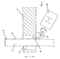
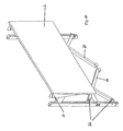
- a work table 1 in a side elevational view in section, wherein the section is parallel to the narrow side of a countertop 2.
- the work table 1 consists of two vertically extending guide rails 3, which are executed in the illustrated embodiment as a support legs, arranged on the back of the worktop 2 and each made of a square tube and advantageously have square cross-section.
- other cross-sectional shapes can be chosen. It is expedient to use as possible cross-sectional shapes that are available as standard tubes on the market and do not require custom-made.
- the outer cross-sectional dimension of the support legs 3 is about 40 to 50 mm.
- each support leg In the lower region of each support leg two obliquely to the support leg 3 extending struts 4,5, for example, by welding, connected, which also consist of a commercial tube, which extend at an angle of about 90 ° to each other and on which the support leg 3 on the Ground supports.
- the support leg 3 is thus formed integrally with the two struts 4,5.
- Both thus integrally formed with the struts 4,5 support legs 3 are by a L-shaped cross-section having plate 6 fixed, but detachable with each other connected.
- This connection takes place, as indicated in the drawing, by screws 7.
- These screws 7 are inserted into so-called gusset plates 8, which are used in the sheet 6.
- these releasable connection gives the opportunity to disassemble the worktable 1 and then to pack the support legs 3 with the struts 4.5 in the smallest space.
- the L-shaped cross-section having sheet 6 can be used as so-called Cable channel can be used.
- the work table 1 also has two trusses 9, the U-shaped sheet metal with a wall thickness of 2.00 to 4.00 mm folded and open at the bottom. At their rear ends, the bridge of these trusses 9 is notched, so that each a cross member 9 can be pushed from above over a support leg 3. Both trusses 9 are through a U-profile sheet 10 with a wall thickness of 1.50 to 3.00 firmly connected.
- This connection can already factory be prepared and designed to be detachable or insoluble. For packaging of the work table 1, however, this connection does not have to be separated because this unit in its base area is not larger than the total area of the worktop.
- each Traverse 9 has an upper, rear and one lower, front roller 11,12, for example, formed by a ball bearing and rotatably held between the legs of a cross member 9 and at a Support leg 3 rest.
- each lateral leg of the trusses 9 a likewise fitting to the vertical support leg 3 slider provided so that ensures a good and safe guidance of the trusses 9 on the support legs 3 is.
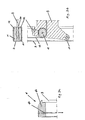
- the U-profile sheet 10 is inserted open at the top between the two trusses 9 and takes a known drive motor with a shaft and at least a cable drum with two guided over pulleys tension cables 13. The arrangement of two cable drums is possible. These parts are in themselves known and were therefore not drawn in the drawing.
- the downward movement of the trusses 9 and thus lowering the worktop 2 is done exclusively by its own weight from worktop 2, trusses 9 and U-profile sheet 10 with the therein Drive parts.
- the drive exerts no forces on the trusses 9 from.
- the drive motor is immediately on a switched off special switch.
- the Verstellhub the worktop 2 is about 600 mm and allows a working height of the worktop 2 between 650 and 1250 mm.
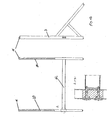
- Figure 2 shows a possible embodiment of the drive of the worktop 2, which is mounted on the guide rails 3 as described above.
- the traction cable 13 is mounted with its one end at the upper end of the guide rail 3.
- the pull rope is on the cable drum 14 by means of the motor 15 and unrolled.
- FIG 3a shows a preferred embodiment of the suspension 16 of the cable 13 at the upper end of the guide rail.
- the suspension 16 consists essentially of a plug 17, which is preferably at least partially positively received by the guide rail 3 and is supported on the wall thereof.
- the rope is arranged so that it can be loaded in tension (represented by the arrow).
- the plug 17 is attached to the guide rail 3 and can be removed again during disassembly.
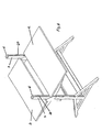
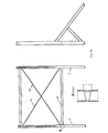
- FIG. 3b shows a preferred embodiment of the mounting of the traverse 9 on the guide rail 3 in two views.
- the rollers 11, 12 engage the inner cross-section of the profile 3, with the rollers 12 at the front and the rollers 11 at the rear.
- the profile must have a slot 20 in which the traverse moves up and down.
- a roller 18 is mounted in the traverse around which the cable 13 (not shown) from the cable drum to the holder 16 (not shown) is deflected.
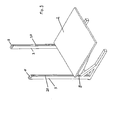
- Figure 4 shows the mounting of the motor 15 and the cable drum 14 shown on the worktop 2, wherein the worktop 2 is not shown.
- the traction cable 13 is guided by the cable drum 14 via a roller 19 to the roller 18. It can be seen that two traction cables 13 run on a roller 14, so that the up and down movement on the two guide rails 3 (only one shown) does not have to be synchronized.
- the person skilled in the art recognizes that three or more pull ropes can also be guided on a cable drum.
- FIGS. 5 to 14 show possible embodiments of the work table according to the invention.
- the worktable has three guide rails 3, so that the worktop is raised or lowered at three points.
- the worktable according to FIG. 10 has a hinge 21 so that the worktop 2 can be folded down and hinges 25 with which the leg braces 26 can be folded.
- the work table is arranged in a box, in order to be able to raise or lower a television, for example.
- the guide rails 3 are mounted on a wall and in Figure 13, the guide rails 3 are designed as support legs and non-positively connected by the cross member 22.
- FIG. 14 shows a further embodiment of the traverse 22, which in the present case cooperates in a form-fitting manner with the support legs 3, which are clamped together by the cables 23.
Abstract
Description
Die Erfindung bezieht sich auf einen höheneinstellbaren Arbeitstisch mit zwei Führungsschienen zur Aufnahme einer Arbeitsplatte, die durch einen Antriebsmotor mit Seiltrommeln und Zugseilen in ihrer Arbeitshöhe einstellbar ist. Ein solcher Arbeitstisch ist z.B. aus Dokument US 5 715 759 A bekannt.The invention relates to a height-adjustable work table with two guide rails for receiving a countertop by a drive motor adjustable with rope drums and pull ropes in their working height. Such a Worktable is e.g. from document US Pat. No. 5,715,759 A.
Weiternin sind Arbeitstische bekannt, zu denen auch Schreibtische oder Werkbänke gehören, die aus einem metallischen Gestell bestehen, welches die sogenannte Arbeitsplatte trägt. Dabei besteht das Gestell zunächst aus einem Untergestell, welches aus mindestens zwei über eine Strebe mit Abstand verbundenen Außenrohren besteht, die eine unterschiedliche Querschnittsform und Querschnittsgröße aufweisen können. In den Außenrohren sind dabei Innenrohre verschiebbar geführt, die entweder ausschließlich über die Arbeitsplatte, bedarfsweise aber auch noch zusätzlich über eine Strebe, miteinander verbunden sind. Jeweils ein Außenrohr und ein Innenrohr bilden dabei ein Stützbein des Arbeitstisches. Um nun die Höhenlage der Arbeitsplatte verändern bzw. vergrößern zu können, ist jeweils im oberen Bereich des Untergestells, vorzugsweise im oberen Bereich des Außenrohres, ein Seil angeschlossen, welches zum unteren Ende des Innenrohres geführt, dort umgelenkt, wieder nach oben geführt und danach im oberen Bereich des Außenrohres in das Untergestell ragt und dort von einer Zugeinheit, die beispielsweise als Seiltrommel ausgebildet sein kann, aufgenommen wird. Dabei sind an die Zugeinheit alle Seile der Stützbeine angeschlossen. Durch entsprechendes Bewegen der Zugeinheit werden nun die Innenrohre aus den Außenrohren allmählich, jedoch in vorgegebenen Grenzen, herausgeschoben, so dass die Arbeitsplatte angehoben wird. Bei einer entgegengesetzten Bewegung der Zugeinheit werden die Zugseile wieder nachgelassen und die Innenrohre bewegen sich aufgrund des Gewichtes, insbesondere der Arbeitsplatte, wieder in die Außenrohre zurück. Die Zugeinheit kann dabei entweder von Hand oder über einen besonderen Antrieb bewegt werden.Also known as work desks, which include desks or workbenches, which consist of a metallic frame, which is the so-called worktop wearing. The frame initially consists of a base, which from at least two outer tubes connected by a strut at a distance which has a different cross-sectional shape and cross-sectional size can have. Inner tubes are displaceably guided in the outer tubes, either exclusively on the worktop, if necessary, but also additionally via a strut, are connected. In each case an outer tube and an inner tube thereby form a support leg of the work table. Order now the To be able to change or enlarge the height of the worktop is in each case upper region of the underframe, preferably in the upper region of the outer tube, a rope connected, which led to the lower end of the inner tube, there deflected, led back up and then in the upper part of the outer tube protrudes into the base and there by a train unit, for example can be designed as a cable drum is recorded. Here are the train unit all ropes of the support legs connected. By appropriate movement The train unit will now the inner tubes from the outer tubes gradually, however within predetermined limits, pushed out, so that the worktop raised becomes. In an opposite movement of the tractor unit are the traction cables slackened again and the inner tubes move due to the weight, especially the worktop, back into the outer tubes. The train unit can be moved either by hand or by a special drive.
Derartige Arbeitstische sind in ihrer Herstellung verhältnismäßig aufwendig und teuer. Dies hängt insbesondere damit zusammen, dass die die Stützbeine bildenden Außen- und Innenrohre Sonderprofile sind und über besondere Gleitstücke sehr genau ineinander geführt werden müssen. Aufgrund der Ausgestaltung des Ober- und Untergestells ist der Arbeitstisch vor seiner Auslieferung immer fertig montiert, was hohe Transportkosten mit sich bringt. Ein solcher Arbeitstisch ist darüber hinaus verhältnismäßig schwer, was sich bei dessen Aufstellung nachteilig auswirkt.Such work tables are relatively expensive to manufacture and expensive. This is particularly related to the fact that the support legs forming Outer and inner tubes are special profiles and about special sliders must be very closely intertwined. Due to the design of the Upper and lower frame, the work table is always ready before its delivery mounted, which brings high transport costs. Such a work table is about it In addition, relatively difficult, which is disadvantageous in its formation effect.
Der Erfindung liegt nun die Aufgabe zugrunde, einen Arbeitstisch mit höheneinstellbarer Arbeitsplatte zu schaffen, der ein verhältnismäßig geringes Gewicht besitzt und äußerst preiswert ist. Darüber hinaus soll der Arbeitstisch so gestaltet sein, dass er leicht in seine Einzelteile zerlegt werden kann, auf kleinem Raum verpackbar ist und von einem Laien problemlos zusammengebaut werden kann.The invention is based on the object, a work table with height adjustable To create a worktop, which has a relatively low weight and is extremely cheap. In addition, the work table should be designed this way be that it can be easily disassembled into its individual parts, packable in a small space is and can be easily assembled by a layman.
Zur Lösung dieser Aufgabe wird gemäß der Erfindung ein Arbeitstisch gemäß Anspruch
1 vorgeschlagen.To solve this problem, according to the invention, a work table according to
Ein derartig ausgebildeter Arbeitstisch besitzt bei hoher Stabilität ein verhältnismäßig geringes Gewicht und ist preiswert herzustellen. Für die Führungsschienen können Standardrohre verwendet werden, so dass keine Sonderanfertigung erforderlich ist. Der Arbeitstisch kann - in Einzelteile zerlegt - bei geringem Platzbedarf in einen Karton verpackt, bei geringen Kosten gelagert und damit auch platzsparend transportiert werden. Seine Ausgestaltung ermöglicht es jedem Laien, den erfindungsgemäßen Arbeitstisch ohne besonderes fachliches Können zusammenzubauen. Die Abwärtsbewegung der Arbeitsplatte erfolgt durch deren Gewicht, so dass eine Quetschgefahr des Benutzers erheblich reduziert ist. Die Seilführung ist so ausgebildet, dass das Seil niemals aus seiner Laufbahn herausfällt. Die Arbeitsplatte kann an mehr als zwei Seilen aufgehängt sein, die jeweils angetrieben sind. Alle Antriebsseile werden auf einer Trommel geführt. Der Aufhängungspunkt liegt oberhalb der höchsten Tischposition. Vorzugsweise schaltet sich der Motor bei Entlastung mindestens eines Seiles vorzugsweise automatisch ab und/oder es erfolgt durch elektronische Ansteuerung eine Drehumkehr des Motors, um eine Verkanten der Arbeitsplatte oder eine Verletzung der Benutzer zu vermeiden. Verschiedene Tischhöhen können abgespeichert werden. Die Arbeitsplatte kann neigbar bzw. komplett wegklappbar gestaltet werden. Such a trained work table has a high stability with a relatively low weight and is inexpensive to manufacture. For the guide rails Standard tubes can be used, so no special order required is. The work table can - disassembled into pieces - at low Space required packed in a box, stored at low cost and therefore also be transported to save space. Its design allows every layman Assemble the work table according to the invention without special skill. The downward movement of the worktop is made by its weight, so that a risk of crushing the user is significantly reduced. The rope guide is designed so that the rope never falls out of its career. The worktop can be hung on more than two ropes, each driven are. All drive cables are guided on a drum. The suspension point is above the highest table position. Preferably, the engine turns on Relief of at least one rope preferably automatically off and / or it takes place by electronic control, a reversal of the motor to a tilting to avoid the worktop or a violation of the user. Various Table heights can be saved. The worktop can be tilted or be designed completely folded away.
Weitere Merkmale eines Arbeitstisches gemäß der Erfindung sind in den Ansprüchen
2 bis 9 offenbart.Further features of a work table according to the invention are in the
Die Erfindung wird nachfolgend anhand der Zeichnungen 1 - 14 erläutert. Diese Erläuterungen sind lediglich beispielhaft und schränken den allgemeinen Erfindungsgedanken nicht ein.
-
Figur 1 - zeigt eine Ausführungsform des erfindungsgemäßen Arbeitstisches.
-
Figur 2 - zeigt eine Ausführungsform des Antriebes der Arbeitsplatte
- Figur 3a
- zeigt eine Ausführungsform der Lagerung des Zugseils
- Figur 3b
- zeigt eine Ausführungsform der Lagerung der Arbeitsplatte an der Führungsschiene
-
Figur 4 - zeigt die Anordnung des Motors an der Tischplatte
- Figuren 5 - 14
- zeigen weitere Ausführungsformen des erfindungsgemäßen Arbeitstisches.
- FIG. 1
- shows an embodiment of the work table according to the invention.
- FIG. 2
- shows an embodiment of the drive of the worktop
- FIG. 3a
- shows an embodiment of the mounting of the traction cable
- FIG. 3b
- shows an embodiment of the mounting of the worktop to the guide rail
- FIG. 4
- shows the arrangement of the motor on the table top
- FIGS. 5 to 14
- show further embodiments of the work table according to the invention.
In Figur 1 ist ein Arbeitstisch 1 gemäß der Erfindung in seitlicher Aufrissdarstellung
im Schnitt gezeigt, wobei der Schnitt parallel zur Schmalseite einer Arbeitsplatte 2
verläuft. Der Arbeitstisch 1 besteht aus zwei senkrecht verlaufenden Führungsschienen
3, die im dargestellten Ausführungsbeispiel als Stützbeinen ausgeführt,
an der Rückseite der Arbeitsplatte 2 angeordnet und jeweils aus einem Vierkantrohr
gefertigt sind und vorteilhaft quadratischen Querschnitt besitzen. Selbstverständlich
können auch andere Querschnittsformen gewählt werden. Dabei ist es
zweckmäßig, möglichst solche Querschnittsformen zu verwenden, die als Standardrohre
auf dem Markt zu erhalten sind und keine Sonderanfertigung erforderlich
machen. Das äußere Querschnittsmaß der Stützbeine 3 beträgt etwa 40 bis 50
mm. Im unteren Bereich jedes Stützbeines sind zwei schräg zum Stützbein 3
verlaufende Streben 4,5, beispielsweise durch Schweißung, angeschlossen, die
ebenfalls aus einem handelsüblichen Rohr bestehen, die zueinander unter einem
Winkel von etwa 90° verlaufen und über die sich das Stützbein 3 auf dem Boden
abstützt. Das Stützbein 3 ist somit mit den beiden Streben 4,5 einstückig ausgebildet.In Figure 1 , a work table 1 according to the invention in a side elevational view in section, wherein the section is parallel to the narrow side of a
Beide derartig mit den Streben 4,5 einstückig ausgebildeten Stützbeine 3 sind
durch ein L-förmigen Querschnitt aufweisendes Blech 6 fest, jedoch lösbar miteinander
verbunden. Diese Verbindung erfolgt, wie in der Zeichnung angedeutet,
durch Schrauben 7. Diese Schrauben 7 werden in sogenannte Knotenbleche 8 eingesteckt,
die im Blech 6 eingesetzt sind. Es ist jedoch auch möglich, diese Teile
formschlüssig, beispielsweise durch "Einhaken" miteinander zu verbinden. Diese
lösbare Verbindung gibt die Möglichkeit, den Arbeitstisch 1 zu zerlegen und dann
die Stützbeine 3 mit den Streben 4,5 auf kleinstem Raum zu verpacken. Bei der
eigentlichen Montage werden also zunächst die beiden Stützbeine 3 aufgestellt und
über das Blech 6 miteinander verbunden. Dadurch entsteht eine stabile, tragende
Einheit. Das einen L-förmigen Querschnitt aufweisende Blech 6 kann als sogenannter
Kabelkanal genutzt werden.Both thus integrally formed with the
Der Arbeitstisch 1 weist ferner zwei Traversen 9 auf, die U-förmig aus Blech mit
einer Wandstärke von 2,00 bis 4,00 mm gekantet und nach unten offen sind. An
ihren rückwärtigen Enden ist der Steg dieser Traversen 9 ausgeklinkt, so dass jeweils
eine Traverse 9 von oben über ein Stützbein 3 aufgeschoben werden kann.
Beide Traversen 9 sind durch ein U-Profilblech 10 mit einer Wandstärke von 1,50
bis 3,00 fest miteinander verbunden. Diese Verbindung kann dabei bereits werksseitig
hergestellt werden und lösbar oder unlösbar ausgelegt sein. Für das Verpakken
des Arbeitstisches 1 muss diese Verbindung jedoch nicht getrennt werden, da
diese Einheit in ihrer Grundfläche nicht größer ist als die Gesamtfläche der Arbeitsplatte.
Um nun die beiden Traversen 9 an den Stützbeinen 3 bewegen und damit
heben und senken zu können, besitzt jede Traverse 9 eine obere, hintere und eine
untere, vordere Laufrolle 11,12, die beispielsweise durch ein Kugellager gebildet
und drehbar zwischen den Schenkeln einer Traverse 9 gehalten sind und an einem
Stützbein 3 anliegen. Zusätzlich ist an jedem seitlichen Schenkel der Traversen 9
ein ebenfalls am senkrechten Stützbein 3 anliegendes Gleitstück vorgesehen, so
dass eine gute und sichere Führung der Traversen 9 an den Stützbeinen 3 sichergestellt
ist.The work table 1 also has two
Das U-Profilblech 10 ist nach oben offen zwischen die beiden Traversen 9 eingesetzt
und nimmt einen an sich bekannten Antriebsmotor mit einer Welle und mindestens
einer Seiltrommel mit zwei über Umlenkrollen geführten Zugseilen 13 auf.
Auch die Anordnung von zwei Seiltrommeln ist möglich. Diese Teile sind an sich
bekannt und wurden deshalb nicht in der Zeichnung eingezeichnet.The
Sobald die vorbeschriebene Montage durchgeführt ist, werden die freien Enden der
Zugseile jeweils an einem oberen Ende der Stützbeine 3, welche dazu besonders
ausgebildet sind, eingehängt. Die Zugseile 13 sind in Umlenkrollen so geführt, dass
diese die Laufnut der Umlenkrollen, auch bei nachlassender Seilspannung, niemals
verlassen können. Dies gilt auch dann, wenn der Arbeitstisch 1 für einen Transport
zerlegt und dazu die Zugseile 13 ausgehängt werden. Nach dem Anschalten des
Antriebsmotors werden nun beide Traversen 9 gleichzeitig und gleichmäßig stufenlos
durch den Motor nach oben gezogen oder nach unten durch ihr Eigengewicht
und das Gewicht der Arbeitsplatte 2 abgelassen. Damit kann die Arbeitsplatte
2, die auf den beiden Traversen 9 beispielsweise mittels Schrauben befestigt ist,
angehoben oder abgesenkt werden. Die Abwärtsbewegung der Traversen 9 und
damit das Absenken der Arbeitsplatte 2 erfolgt ausschließlich durch das Eigengewicht
von Arbeitsplatte 2, Traversen 9 und U-Profilblech 10 mit den darin befindlichen
Antriebsteilen. Der Antrieb übt dazu keinerlei Kräfte auf die Traversen 9 aus.
Bei nachlassender Spannung der Zugseile wird der Antriebsmotor sofort über einen
besonderen Schalter abgeschaltet. Der Verstellhub der Arbeitsplatte 2 beträgt etwa
600 mm und ermöglicht eine Arbeitshöhe der Arbeitsplatte 2 zwischen 650 und
1250 mm.Once the above assembly is performed, the free ends of the
Pull ropes each at an upper end of the
In Abänderung des erläuterten Ausführungsbeispieles ist es möglich, die senkrechten
Rohre der Stützbeine 3 nicht rückseitig, sondern seitlich an der Arbeitsplatte
2 anzuordnen. Die Traversen 9 sollten dann jedoch möglichst quer vor den
Stützbeinen 3 verlaufen, damit eine ausreichende Standsicherheit des Arbeitstisches
1 gewährleistet ist. Gegebenenfalls sind dann auch die Stützbeine 9 mit den
Streben 4,5 anders auszubilden.In a modification of the illustrated embodiment, it is possible to use the vertical
Tubes of the
Figur 2 zeigt eine mögliche Ausgestaltungsform des Antriebes der Arbeitsplatte 2,
die wie oben beschrieben an den Führungsschienen 3 gelagert ist. Das Zugseil 13
ist mit seinem einen Ende am oberen Ende der Führungsschiene 3 gelagert. Das
Zugseil wird auf der Seiltrommel 14 mittels des Motors 15 auf und abgerollt. Figure 2 shows a possible embodiment of the drive of the
Figur 3a zeigt eine bevorzugte Ausführungsform der Aufhängung 16 des Seiles 13
an dem oberen Ende der Führungsschiene. Die Aufhängung 16 besteht im wesentlichen
aus einem Stopfen 17, der vorzugsweise zumindest teilweise formschlüssig
von der Führungsschiene 3 aufgenommen wird und sich auf deren Wandung abstützt.
In dem Stopfen 17 ist das Seil so angeordnet, dass es auf Zug (durch den
Pfeil dargestellt) belastbar ist. Zur Montage des erfindungsgemäßen Arbeitstisches
wird der Stopfen 17 auf die Führungsschiene 3 aufgesteckt und kann bei der Demontage
wieder abgenommen werden. Figure 3a shows a preferred embodiment of the
Figur 3b zeigt eine bevorzugte Ausführungsform der Lagerung der Traverse 9 an
der Führungsschiene 3 in zwei Ansichten. In dem vorliegenden Fall greifen die
Rollen 11, 12 an dem inneren Querschnitt des Profils 3 an, wobei die Rollen 12
vorne und die Rollen 11 hinten angeordnet sind. Der Fachmann erkennt, dass das
Profil in diesem Fall einen Schlitz 20 aufweisen muss, in dem sich die Traverse auf-
und ab bewegt. In der Traverse ist zusätzlich eine Rolle 18 angebracht, um die das
Seil 13 von der Seiltrommel (nicht dargestellt) zu der Halterung 16 (nicht dargestellt)
umgelenkt wird. FIG. 3b shows a preferred embodiment of the mounting of the
Figur 4 zeigt die Lagerung des Motors 15 und der Seiltrommel 14 an der Arbeitsplatte
2 dargestellt, wobei die Arbeitsplatte 2 nicht dargestellt ist. Das Zugseil 13
wird von der Seiltrommel 14 über eine Rolle 19 zu der Rolle 18 geleitet. Es ist zu
erkennen, dass zwei Zugseile 13 auf einer Rolle 14 laufen, so dass die Auf- und
Abwärtsbewegung an den beiden Führungsschienen 3 (nur eine dargestellt) nicht
synchronisiert werden muss. Der Fachmann erkennt, dass auch drei oder mehr
Zugseile auf einer Seiltrommel geführt werden können. Figure 4 shows the mounting of the
Figuren 5 - 14 zeigen mögliche Ausführungsformen des erfindungsgemäßen Arbeitstisches.
Bei der Ausführungsform gemäß Figur 8 weist der Arbeitstisch drei Führungsschienen
3 auf, so dass die Arbeitsplatte an drei Stellen angehoben bzw. abgesenkt
wird. Der Arbeitstisch gemäß Figur 10 weist ein Scharnier 21 auf, so dass
die Arbeitsplatte 2 abklappbar ist und Scharniere 25, mit denen die Beinausleger 26
einklappbar sind. Bei der Ausführungsform gemäß Figur 11 ist der Arbeitstisch in
einer Kiste angeordnet, um beispielsweise einen Femseher anheben oder absenken
zu können. In Figur 12 sind die Führungsschienen 3 an einer Wand montiert
und in Figur 13 sind die Führungsschienen 3 als Stützbeine ausgeführt und durch
die Traverse 22 kraftschlüssig miteinander verbunden. Figur 14 zeigt eine weitere
Ausführungsform der Traverse 22, die in dem vorliegenden Fall formschlüssig mit
den Stützbeinen 3 zusammenwirkt , die durch die Seile 23 miteinander verspannt
sind. FIGS. 5 to 14 show possible embodiments of the work table according to the invention. In the embodiment according to FIG. 8, the worktable has three
Claims (7)
- A height adjustable work table having at least two guide rails (3) for receiving a work plate (2) the working height of which is adjustable by a drive motor by means of at least one cable drum and of pull cables, each guide rail (3) being formed by a profile and the work plate (2) being slidably carried on the guide rails in such a manner that the work plate moves downward from its own weight and the guide rails (3) comprising means (16) by which a respective one of the ends of the pull cables (13) is adapted to be hung preferably to the upper ends of the guide rails (3), characterized in that the drive motor (5) with the cable drum (14) is disposed in the region of the work plate (2).
- The work table as set forth in claim 1, characterized in that the work plate (2) comprises a means (11, 12) that cooperates with the guide rails (3) on the inner and/or outer cross section.
- The work table as set forth in any one of the afore mentioned claims, characterized in that the guide rail (3) is substantially configured to be a rectangular tube.
- The work table as set forth in claim 2, or 3 if dependent on 2, characterized in that the means is a front castor and a rear castor (11, 12).
- The work table as set forth in claim 4, characterized in that the front castor (12) fits against the bottom and the rear castor (11) against the top and each against an outer cross section of the guide rail (3).
- The work table as set forth in claim 4, characterized in that the front castor (12) fits against the top and the rear castor (11) against the bottom and each against the inner cross section of the guide rail (3).
- The work table as set forth in at least one of the claims 4 through 6, characterized in that the castors (11, 12) are formed by ball bearings.
Applications Claiming Priority (3)
| Application Number | Priority Date | Filing Date | Title |
|---|---|---|---|
| DE20209604U | 2002-06-20 | ||
| DE20209604U DE20209604U1 (en) | 2002-06-20 | 2002-06-20 | Height adjustable work table |
| PCT/EP2003/002767 WO2004000067A1 (en) | 2002-06-20 | 2003-03-17 | Height adjustable working table |
Publications (2)
| Publication Number | Publication Date |
|---|---|
| EP1517625A1 EP1517625A1 (en) | 2005-03-30 |
| EP1517625B1 true EP1517625B1 (en) | 2005-11-02 |
Family
ID=7972389
Family Applications (1)
| Application Number | Title | Priority Date | Filing Date |
|---|---|---|---|
| EP03712042A Expired - Lifetime EP1517625B1 (en) | 2002-06-20 | 2003-03-17 | Height adjustable working table |
Country Status (8)
| Country | Link |
|---|---|
| US (1) | US20050172869A1 (en) |
| EP (1) | EP1517625B1 (en) |
| AT (1) | ATE308261T1 (en) |
| AU (1) | AU2003218784A1 (en) |
| DE (2) | DE20209604U1 (en) |
| DK (1) | DK1517625T3 (en) |
| ES (1) | ES2252662T3 (en) |
| WO (1) | WO2004000067A1 (en) |
Families Citing this family (14)
| Publication number | Priority date | Publication date | Assignee | Title |
|---|---|---|---|---|
| CA2814945C (en) | 2012-05-24 | 2019-04-30 | Daniel J. Flaherty | Adjustable desktop platform |
| CA2887948C (en) * | 2013-08-12 | 2023-10-17 | Dirtt Environmental Solutions, Ltd. | Wall-mounted devices, systems, and methods for selectively positioning objects |
| EP3001930A1 (en) * | 2014-10-03 | 2016-04-06 | Vitra Patente AG | Height-adjustable table |
| US9414670B2 (en) * | 2014-12-12 | 2016-08-16 | Boka Import Export, Inc. | Collapsible table having interlocking assembly |
| US9723919B1 (en) * | 2016-02-09 | 2017-08-08 | Symbiote, Inc. | Combination foldable and adjustable workstation |
| US11019920B2 (en) | 2016-09-23 | 2021-06-01 | Varidesk, Llc | Electrically-lifted computer desk and office desk thereof |
| CN206390562U (en) | 2016-09-23 | 2017-08-11 | 廖良成 | Electric lifting computer desk and its desk |
| WO2018213062A1 (en) | 2017-05-19 | 2018-11-22 | Dirtt Environmental Solutions, Inc. | Systems and methods for selectively positioning wall-mounted devices |
| TWM581843U (en) * | 2019-01-10 | 2019-08-11 | 可文山 | Foldable table legs |
| CA3131309A1 (en) | 2019-03-20 | 2020-09-24 | Dirtt Environmental Solutions Ltd. | Height adjusting and leveling worksurface cantilever |
| DE102021000657B4 (en) | 2020-09-14 | 2024-05-02 | Paul Wulff | Device for adjusting the height of a table top, in particular a desk top |
| US11439229B2 (en) * | 2020-09-16 | 2022-09-13 | Bridgewater Strategies, LLC | Adjustable height workstation |
| USD1023624S1 (en) | 2021-08-16 | 2024-04-23 | AMQ Solutions, LLC | Collapsible workstation |
| USD1023627S1 (en) | 2021-08-16 | 2024-04-23 | AMQ Solutions, LLC | Workstation |
Family Cites Families (16)
| Publication number | Priority date | Publication date | Assignee | Title |
|---|---|---|---|---|
| US3123024A (en) * | 1964-03-03 | Self-leveling devices | ||
| US2749196A (en) * | 1953-10-23 | 1956-06-05 | Joseph A Wolfe | Track and bed table carriage supported from bed rail |
| US2875012A (en) * | 1954-06-08 | 1959-02-24 | Claude J Riley | Disappearing medicine cabinet |
| US3339795A (en) * | 1965-03-24 | 1967-09-05 | Lincoln Mfg Co | Storage apparatus |
| US3411464A (en) * | 1966-06-16 | 1968-11-19 | Lincoln Mfg Company | Vertically moving cantilever platform |
| SU328630A1 (en) * | 1970-02-24 | 1976-05-25 | Минский Опытный Завод Скб-3 | Drawing table |
| US3937095A (en) * | 1974-10-24 | 1976-02-10 | Lincoln Manufacturing Company, Inc. | Self adjusting elevator |
| DE8138223U1 (en) * | 1981-12-31 | 1982-05-19 | Horst Häusser Metallwaren GmbH, 7062 Rudersberg | HEIGHT-ADJUSTABLE WORKTOP |
| US4553726A (en) * | 1983-09-19 | 1985-11-19 | Ex-Cell-O Corporation | Adjustable height seat apparatus for combat vehicle |
| US4629072A (en) * | 1984-12-17 | 1986-12-16 | P.O.P. Displays, Inc. | Apparatus for storing and dispensing stacked articles |
| US4651652A (en) * | 1984-12-20 | 1987-03-24 | At&T Bell Laboratories | Vertically adjustable work desk |
| US5366203A (en) * | 1989-07-31 | 1994-11-22 | Safety Lock And Lift, Ltd. | Projector ceiling lift |
| WO1995027420A1 (en) * | 1994-04-06 | 1995-10-19 | Eun Ok Lee | Apparatus for setting furniture in variable elevated positions |
| US5687654A (en) * | 1996-04-12 | 1997-11-18 | Huggins; Lloyd | Vertically adjustable table |
| WO2000024290A1 (en) * | 1998-10-22 | 2000-05-04 | Protoned B.V. | Height-adjustable pc workstation |
| USD458046S1 (en) * | 2000-10-16 | 2002-06-04 | Vitra Patente Ag | Office furniture |
-
2002
- 2002-06-20 DE DE20209604U patent/DE20209604U1/en not_active Expired - Lifetime
-
2003
- 2003-03-17 AT AT03712042T patent/ATE308261T1/en active
- 2003-03-17 EP EP03712042A patent/EP1517625B1/en not_active Expired - Lifetime
- 2003-03-17 DE DE50301570T patent/DE50301570D1/en not_active Expired - Lifetime
- 2003-03-17 DK DK03712042T patent/DK1517625T3/en active
- 2003-03-17 US US10/518,135 patent/US20050172869A1/en not_active Abandoned
- 2003-03-17 AU AU2003218784A patent/AU2003218784A1/en not_active Abandoned
- 2003-03-17 WO PCT/EP2003/002767 patent/WO2004000067A1/en not_active Application Discontinuation
- 2003-03-17 ES ES03712042T patent/ES2252662T3/en not_active Expired - Lifetime
Also Published As
| Publication number | Publication date |
|---|---|
| EP1517625A1 (en) | 2005-03-30 |
| US20050172869A1 (en) | 2005-08-11 |
| DE20209604U1 (en) | 2002-08-22 |
| ATE308261T1 (en) | 2005-11-15 |
| ES2252662T3 (en) | 2006-05-16 |
| DK1517625T3 (en) | 2006-03-20 |
| DE50301570D1 (en) | 2005-12-08 |
| AU2003218784A1 (en) | 2004-01-06 |
| WO2004000067A1 (en) | 2003-12-31 |
Similar Documents
| Publication | Publication Date | Title |
|---|---|---|
| EP1517625B1 (en) | Height adjustable working table | |
| DE8138223U1 (en) | HEIGHT-ADJUSTABLE WORKTOP | |
| EP3200653A1 (en) | Height-adjustable table | |
| DE3605637A1 (en) | FITTING FOR A CABINET WITH HINGE PIVOTING DOOR | |
| DE102006018421A1 (en) | System for securing furniture and equipment that is at risk of tilting | |
| AT406006B (en) | EXTENSION DEVICE FOR CUPBOARD UNITS | |
| CH678798A5 (en) | ||
| EP1190646B1 (en) | Drawer for an extensible furniture part | |
| DE2419546B2 (en) | CABINET WITH PULL-OUT DRAWER ELEMENTS | |
| EP0242811B1 (en) | Table and/or cupboard to be put up against a vertical wall | |
| DE2415572C3 (en) | Furniture frames, in particular table frames | |
| DE19706246B4 (en) | Telescopic cupboard drawer | |
| DE102020122696B4 (en) | furniture component | |
| CH670749A5 (en) | Cabinet and/or table mounted on vertical wall | |
| DE102020122707B4 (en) | furniture component | |
| DE19718256A1 (en) | Pull-out arrangement for drawers in cupboard, with guide and runner rails | |
| AT403649B (en) | EXTENSION GUIDE SET FOR A DRAWER WHICH CAN BE MOVED IN A FURNITURE | |
| DE2840090A1 (en) | Drawer guide with runners for smooth easy inward movement - has guide rails on drawer sides with three runners preventing jamming | |
| DE8332821U1 (en) | FURNITURE WITH AT LEAST ONE DRAWER | |
| DE4133808A1 (en) | Roller conveyor frame with two side sections - is joined by cross pieces, and has recesses in top edges for support roller axles | |
| DE4022459A1 (en) | Base frame for table, desk or bench - consists of table top on base sections, with trough shaped part in which are lengthwise struts | |
| AT404787B (en) | SEAT FURNITURE | |
| DE3635592A1 (en) | Piece of cupboard and/or table furniture mountable on a vertical wall | |
| AT5925U1 (en) | ROLLER COVER FOR A SUPPORTING SLIDING GATE | |
| DE2835170A1 (en) | Parallelogram guide rod system - is for kitchen machines housed in cupboards and has ball bearings to allow smooth displacement between rest and work positions |
Legal Events
| Date | Code | Title | Description |
|---|---|---|---|
| PUAI | Public reference made under article 153(3) epc to a published international application that has entered the european phase |
Free format text: ORIGINAL CODE: 0009012 |
|
| 17P | Request for examination filed |
Effective date: 20050120 |
|
| AK | Designated contracting states |
Kind code of ref document: A1 Designated state(s): AT BE BG CH CY CZ DE DK EE ES FI FR GB GR HU IE IT LI LU MC NL PT RO SE SI SK TR |
|
| AX | Request for extension of the european patent |
Extension state: AL LT LV MK |
|
| GRAP | Despatch of communication of intention to grant a patent |
Free format text: ORIGINAL CODE: EPIDOSNIGR1 |
|
| GRAS | Grant fee paid |
Free format text: ORIGINAL CODE: EPIDOSNIGR3 |
|
| GRAA | (expected) grant |
Free format text: ORIGINAL CODE: 0009210 |
|
| DAX | Request for extension of the european patent (deleted) | ||
| AK | Designated contracting states |
Kind code of ref document: B1 Designated state(s): AT BE BG CH CY CZ DE DK EE ES FI FR GB GR HU IE IT LI LU MC NL PT RO SE SI SK TR |
|
| PG25 | Lapsed in a contracting state [announced via postgrant information from national office to epo] |
Ref country code: IE Free format text: LAPSE BECAUSE OF FAILURE TO SUBMIT A TRANSLATION OF THE DESCRIPTION OR TO PAY THE FEE WITHIN THE PRESCRIBED TIME-LIMIT Effective date: 20051102 Ref country code: IT Free format text: LAPSE BECAUSE OF FAILURE TO SUBMIT A TRANSLATION OF THE DESCRIPTION OR TO PAY THE FEE WITHIN THE PRESCRIBED TIME-LIMIT;WARNING: LAPSES OF ITALIAN PATENTS WITH EFFECTIVE DATE BEFORE 2007 MAY HAVE OCCURRED AT ANY TIME BEFORE 2007. THE CORRECT EFFECTIVE DATE MAY BE DIFFERENT FROM THE ONE RECORDED. Effective date: 20051102 Ref country code: CZ Free format text: LAPSE BECAUSE OF FAILURE TO SUBMIT A TRANSLATION OF THE DESCRIPTION OR TO PAY THE FEE WITHIN THE PRESCRIBED TIME-LIMIT Effective date: 20051102 Ref country code: SK Free format text: LAPSE BECAUSE OF FAILURE TO SUBMIT A TRANSLATION OF THE DESCRIPTION OR TO PAY THE FEE WITHIN THE PRESCRIBED TIME-LIMIT Effective date: 20051102 Ref country code: SI Free format text: LAPSE BECAUSE OF FAILURE TO SUBMIT A TRANSLATION OF THE DESCRIPTION OR TO PAY THE FEE WITHIN THE PRESCRIBED TIME-LIMIT Effective date: 20051102 Ref country code: FI Free format text: LAPSE BECAUSE OF FAILURE TO SUBMIT A TRANSLATION OF THE DESCRIPTION OR TO PAY THE FEE WITHIN THE PRESCRIBED TIME-LIMIT Effective date: 20051102 Ref country code: RO Free format text: LAPSE BECAUSE OF FAILURE TO SUBMIT A TRANSLATION OF THE DESCRIPTION OR TO PAY THE FEE WITHIN THE PRESCRIBED TIME-LIMIT Effective date: 20051102 |
|
| REG | Reference to a national code |
Ref country code: GB Ref legal event code: FG4D Free format text: NOT ENGLISH |
|
| REG | Reference to a national code |
Ref country code: CH Ref legal event code: EP |
|
| REF | Corresponds to: |
Ref document number: 50301570 Country of ref document: DE Date of ref document: 20051208 Kind code of ref document: P |
|
| PG25 | Lapsed in a contracting state [announced via postgrant information from national office to epo] |
Ref country code: BG Free format text: LAPSE BECAUSE OF FAILURE TO SUBMIT A TRANSLATION OF THE DESCRIPTION OR TO PAY THE FEE WITHIN THE PRESCRIBED TIME-LIMIT Effective date: 20060202 Ref country code: SE Free format text: LAPSE BECAUSE OF FAILURE TO SUBMIT A TRANSLATION OF THE DESCRIPTION OR TO PAY THE FEE WITHIN THE PRESCRIBED TIME-LIMIT Effective date: 20060202 Ref country code: GR Free format text: LAPSE BECAUSE OF FAILURE TO SUBMIT A TRANSLATION OF THE DESCRIPTION OR TO PAY THE FEE WITHIN THE PRESCRIBED TIME-LIMIT Effective date: 20060202 |
|
| GBT | Gb: translation of ep patent filed (gb section 77(6)(a)/1977) |
Effective date: 20060213 |
|
| REG | Reference to a national code |
Ref country code: DK Ref legal event code: T3 |
|
| PG25 | Lapsed in a contracting state [announced via postgrant information from national office to epo] |
Ref country code: LU Free format text: LAPSE BECAUSE OF NON-PAYMENT OF DUE FEES Effective date: 20060331 Ref country code: BE Free format text: LAPSE BECAUSE OF NON-PAYMENT OF DUE FEES Effective date: 20060331 Ref country code: MC Free format text: LAPSE BECAUSE OF NON-PAYMENT OF DUE FEES Effective date: 20060331 |
|
| PG25 | Lapsed in a contracting state [announced via postgrant information from national office to epo] |
Ref country code: PT Free format text: LAPSE BECAUSE OF FAILURE TO SUBMIT A TRANSLATION OF THE DESCRIPTION OR TO PAY THE FEE WITHIN THE PRESCRIBED TIME-LIMIT Effective date: 20060403 |
|
| PG25 | Lapsed in a contracting state [announced via postgrant information from national office to epo] |
Ref country code: HU Free format text: LAPSE BECAUSE OF FAILURE TO SUBMIT A TRANSLATION OF THE DESCRIPTION OR TO PAY THE FEE WITHIN THE PRESCRIBED TIME-LIMIT Effective date: 20060503 |
|
| REG | Reference to a national code |
Ref country code: ES Ref legal event code: FG2A Ref document number: 2252662 Country of ref document: ES Kind code of ref document: T3 |
|
| REG | Reference to a national code |
Ref country code: IE Ref legal event code: FD4D |
|
| ET | Fr: translation filed | ||
| PLBE | No opposition filed within time limit |
Free format text: ORIGINAL CODE: 0009261 |
|
| STAA | Information on the status of an ep patent application or granted ep patent |
Free format text: STATUS: NO OPPOSITION FILED WITHIN TIME LIMIT |
|
| 26N | No opposition filed |
Effective date: 20060803 |
|
| REG | Reference to a national code |
Ref country code: CH Ref legal event code: PL |
|
| BERE | Be: lapsed |
Owner name: SCHMIDT, RAINER Effective date: 20060331 |
|
| PG25 | Lapsed in a contracting state [announced via postgrant information from national office to epo] |
Ref country code: LI Free format text: LAPSE BECAUSE OF NON-PAYMENT OF DUE FEES Effective date: 20070331 Ref country code: CH Free format text: LAPSE BECAUSE OF NON-PAYMENT OF DUE FEES Effective date: 20070331 |
|
| PG25 | Lapsed in a contracting state [announced via postgrant information from national office to epo] |
Ref country code: EE Free format text: LAPSE BECAUSE OF FAILURE TO SUBMIT A TRANSLATION OF THE DESCRIPTION OR TO PAY THE FEE WITHIN THE PRESCRIBED TIME-LIMIT Effective date: 20051102 |
|
| PG25 | Lapsed in a contracting state [announced via postgrant information from national office to epo] |
Ref country code: TR Free format text: LAPSE BECAUSE OF FAILURE TO SUBMIT A TRANSLATION OF THE DESCRIPTION OR TO PAY THE FEE WITHIN THE PRESCRIBED TIME-LIMIT Effective date: 20051102 |
|
| PG25 | Lapsed in a contracting state [announced via postgrant information from national office to epo] |
Ref country code: CY Free format text: LAPSE BECAUSE OF FAILURE TO SUBMIT A TRANSLATION OF THE DESCRIPTION OR TO PAY THE FEE WITHIN THE PRESCRIBED TIME-LIMIT Effective date: 20051102 |
|
| PGFP | Annual fee paid to national office [announced via postgrant information from national office to epo] |
Ref country code: ES Payment date: 20140324 Year of fee payment: 12 |
|
| REG | Reference to a national code |
Ref country code: FR Ref legal event code: PLFP Year of fee payment: 13 |
|
| PGFP | Annual fee paid to national office [announced via postgrant information from national office to epo] |
Ref country code: DK Payment date: 20150330 Year of fee payment: 13 |
|
| PGFP | Annual fee paid to national office [announced via postgrant information from national office to epo] |
Ref country code: AT Payment date: 20150330 Year of fee payment: 13 |
|
| PGFP | Annual fee paid to national office [announced via postgrant information from national office to epo] |
Ref country code: FR Payment date: 20150330 Year of fee payment: 13 |
|
| REG | Reference to a national code |
Ref country code: ES Ref legal event code: FD2A Effective date: 20160427 |
|
| PG25 | Lapsed in a contracting state [announced via postgrant information from national office to epo] |
Ref country code: ES Free format text: LAPSE BECAUSE OF NON-PAYMENT OF DUE FEES Effective date: 20150318 |
|
| REG | Reference to a national code |
Ref country code: DK Ref legal event code: EBP Effective date: 20160331 |
|
| REG | Reference to a national code |
Ref country code: AT Ref legal event code: MM01 Ref document number: 308261 Country of ref document: AT Kind code of ref document: T Effective date: 20160317 |
|
| REG | Reference to a national code |
Ref country code: FR Ref legal event code: ST Effective date: 20161130 |
|
| PG25 | Lapsed in a contracting state [announced via postgrant information from national office to epo] |
Ref country code: FR Free format text: LAPSE BECAUSE OF NON-PAYMENT OF DUE FEES Effective date: 20160331 |
|
| PG25 | Lapsed in a contracting state [announced via postgrant information from national office to epo] |
Ref country code: AT Free format text: LAPSE BECAUSE OF NON-PAYMENT OF DUE FEES Effective date: 20160317 |
|
| PG25 | Lapsed in a contracting state [announced via postgrant information from national office to epo] |
Ref country code: DK Free format text: LAPSE BECAUSE OF NON-PAYMENT OF DUE FEES Effective date: 20160331 |
|
| PGFP | Annual fee paid to national office [announced via postgrant information from national office to epo] |
Ref country code: GB Payment date: 20220104 Year of fee payment: 20 Ref country code: DE Payment date: 20220103 Year of fee payment: 20 |
|
| PGFP | Annual fee paid to national office [announced via postgrant information from national office to epo] |
Ref country code: NL Payment date: 20220101 Year of fee payment: 20 |
|
| REG | Reference to a national code |
Ref country code: DE Ref legal event code: R071 Ref document number: 50301570 Country of ref document: DE |
|
| REG | Reference to a national code |
Ref country code: NL Ref legal event code: MK Effective date: 20230316 |
|
| REG | Reference to a national code |
Ref country code: GB Ref legal event code: PE20 Expiry date: 20230316 |
|
| PG25 | Lapsed in a contracting state [announced via postgrant information from national office to epo] |
Ref country code: GB Free format text: LAPSE BECAUSE OF EXPIRATION OF PROTECTION Effective date: 20230316 |