EP0387199B1 - Abdeckung für ein an einer Wand befestigtes Eckventil - Google Patents
Abdeckung für ein an einer Wand befestigtes Eckventil Download PDFInfo
- Publication number
- EP0387199B1 EP0387199B1 EP90810162A EP90810162A EP0387199B1 EP 0387199 B1 EP0387199 B1 EP 0387199B1 EP 90810162 A EP90810162 A EP 90810162A EP 90810162 A EP90810162 A EP 90810162A EP 0387199 B1 EP0387199 B1 EP 0387199B1
- Authority
- EP
- European Patent Office
- Prior art keywords
- cover
- shaped parts
- saucer
- wall
- corner valve
- Prior art date
- Legal status (The legal status is an assumption and is not a legal conclusion. Google has not performed a legal analysis and makes no representation as to the accuracy of the status listed.)
- Expired - Lifetime
Links
- 230000001174 ascending effect Effects 0.000 claims 1
- 230000001747 exhibiting effect Effects 0.000 claims 1
- 230000000284 resting effect Effects 0.000 abstract 1
- 230000000630 rising effect Effects 0.000 description 3
- 230000001419 dependent effect Effects 0.000 description 1
- 238000002347 injection Methods 0.000 description 1
- 239000007924 injection Substances 0.000 description 1
- 238000003466 welding Methods 0.000 description 1
Images
Classifications
-
- E—FIXED CONSTRUCTIONS
- E03—WATER SUPPLY; SEWERAGE
- E03C—DOMESTIC PLUMBING INSTALLATIONS FOR FRESH WATER OR WASTE WATER; SINKS
- E03C1/00—Domestic plumbing installations for fresh water or waste water; Sinks
- E03C1/02—Plumbing installations for fresh water
- E03C1/04—Water-basin installations specially adapted to wash-basins or baths
- E03C1/042—Arrangements on taps for wash-basins or baths for connecting to the wall
-
- F—MECHANICAL ENGINEERING; LIGHTING; HEATING; WEAPONS; BLASTING
- F16—ENGINEERING ELEMENTS AND UNITS; GENERAL MEASURES FOR PRODUCING AND MAINTAINING EFFECTIVE FUNCTIONING OF MACHINES OR INSTALLATIONS; THERMAL INSULATION IN GENERAL
- F16K—VALVES; TAPS; COCKS; ACTUATING-FLOATS; DEVICES FOR VENTING OR AERATING
- F16K27/00—Construction of housing; Use of materials therefor
- F16K27/12—Covers for housings
-
- E—FIXED CONSTRUCTIONS
- E03—WATER SUPPLY; SEWERAGE
- E03C—DOMESTIC PLUMBING INSTALLATIONS FOR FRESH WATER OR WASTE WATER; SINKS
- E03C2201/00—Details, devices or methods not otherwise provided for
- E03C2201/50—Constructional features of escutcheons for domestic plumbing installations
Definitions
- the invention relates to a cover according to the preamble of independent claim 1.
- a cover of this type is known from US-A-4,301,828. This has a plate with a flange for its attachment, which is connected to a wall by means of rivets or screws or also by welding. The plate must be connected to the wall before the corner valve is attached. It is therefore not possible to attach the cover to an already installed corner valve.
- a similar, known cover has a cylindrical sleeve with a lateral passage into which the corner valve is inserted.
- a rosette, another sleeve-shaped part, a lid and other parts are necessary here to completely cover the corner valve and to fix the cover. So that the cover can be installed or replaced, the corner valve must not be connected to the inlet and outlet pipe parts. this means that it may have to be removed to attach the cover.
- Another disadvantage is that this cover is largely restricted to cylindrical shapes.
- the invention has for its object to provide a cover of the type mentioned, which can also be attached to a corner valve that is already connected and possibly detached and which is largely free in terms of its shape.
- the task is solved by the invention according to claim 1.
- the means for fastening the cover are pushed onto the corner valve in the case of at least partially separated shell-shaped parts.
- the shell-shaped parts are then placed against one another, completely enclosing the means mentioned and the corner valve. Finally, the two parts mentioned are connected to each other. This is also possible when the angle valve is connected and the cover can be removed just as easily.
- the outer shape of these bowl-shaped parts is essentially not subject to any restriction, which is why the shape of the cover according to the invention can be adapted, for example, to a cistern.
- the two shell-shaped parts are hingedly connected to one another via a joint.
- This further development makes it possible to implement the cover from very few individual parts, for example from two individual parts. If, according to an advantageous development, this joint consists of two film hinges and if the means for fastening the cover are arranged between these hinges, the most essential part of the cover can be realized with a single injection molded part.
- a particularly simple assembly of the cover is obtained when it can be attached to the corner valve laterally.
- a part is attached between the shell-shaped parts with which the cover can be clamped against the wall, it is possible to achieve a secure attachment of the cover in a simple manner even with different wall distances of the corner valve.
- the tensioning of the cover against the wall is solved in a structurally particularly advantageous manner in that a clamping ring with a helically rising surface is rotatably mounted between the shell-shaped parts. This clamping ring is turned until the helically rising surface rests on the part of the angle valve running parallel to the wall and the connecting part clamps on the wall.
- the cover has two shell-shaped parts 1a and 1b, which are connected to one another in an articulated manner by an integrally formed connecting part 15. Parts 1a and 1b can be pivoted independently of one another by a film hinge 5 each.
- a fastening sleeve 3 is arranged with a lateral opening 4 for fastening the cover to the corner valve.
- the mounting sleeve 3 is stepped at the free end for the rotatable mounting of a clamping ring 10.
- the clamping ring 10 has a slot 10a on the side, so that this ring is radially limited stretchable.
- the shell-shaped parts 1a and 1b can be folded into the position shown in FIGS. 1 and 2.
- two locking cams 12 are spaced apart and parallel.
- a lid 2 is snapped onto this latching cam 12.
- the cams 12 are dimensioned such that the cover can be displaced to a limited extent in its longitudinal direction.
- This cover 2 firmly connects the two parts 1a and 1b.
- To release the lid is in the direction of arrow 17 to pushed outwards about half its length. In this position it can be gripped and disengaged at the protruding end.
- stepped edges 13 also engage in one another, so that the parts 1a and 1b cannot be moved relative to one another.
- an aperture 7 with an opening 8 is inserted into the opening 6 for the passage of the corner valve 9b.
- the diaphragm 7 is open at the side and can be pushed onto the part 9b under stretching and can be displaced in the opening 6 to a limited extent.
- the clamping ring 10 and the fastening sleeve 3 are each pushed laterally onto the corner valve 9 while being stretched. These parts are now assembled and the clamping ring is rotated until an attached helically rising surface 11 is present on part 9b of the corner valve 9. By further turning the clamping ring, the connecting part 15 is clamped to the wall 14. Now the two parts 1a and 1b are folded together and the cover 2 is put on. As shown in FIGS. 1 and 2, the cover 1 is detachably fixed to the corner valve 9. With the above actions in reverse order, the cover 1 can be removed in a simple manner and without tools.
Landscapes
- Engineering & Computer Science (AREA)
- General Engineering & Computer Science (AREA)
- Public Health (AREA)
- Health & Medical Sciences (AREA)
- Life Sciences & Earth Sciences (AREA)
- Hydrology & Water Resources (AREA)
- Mechanical Engineering (AREA)
- Water Supply & Treatment (AREA)
- Valve Housings (AREA)
- Clamps And Clips (AREA)
- Body Structure For Vehicles (AREA)
- Road Signs Or Road Markings (AREA)
- Building Environments (AREA)
Description
- Die Erfindung betrifft eine Abdeckung nach dem Oberbegriff des unabhängigen Patentanspruchs 1. Eine Abdeckung dieser Gattung ist durch die US-A-4,301,828 bekannt. Diese weist zu ihrer Befestigung eine Platte mit einem Flansch auf, die mittels Nieten oder Schrauben oder auch durch Schweissung mit einer Wand verbunden wird. Die Platte muss vor dem Anbringen des Eckventils mit der Wand verbunden werden. Ein Anbringen der Abdeckung an einem bereits montierten Eckventil ist deshalb nicht möglich.
- Eine ähnliche, bekannte Abdeckung weist eine zylindrische Hülse mit einem seitlichen Durchgang auf, in die das Eckventil eingesetzt wird. Eine Rosette, ein weiterer hülsenförmiger Teil, ein Deckel sowie weitere Teile sind hier notwendig, um das Eckventil vollständig abzudecken und die Abdeckung zu fixieren. Damit die Abdeckung montiert oder ausgewechselt werden kann, darf das Eckventil an den zu- und wegführenden Leitungsteilen nicht angeschlossen sein, das heisst es muss gegebenenfalls zum Anbringen der Abdek- kung abmontiert werden. Nachteilig ist ebenfalls, dass diese Abdeckung weitgehend auf zylindrische Formen einge- schränkt ist.
- Der Erfindung liegt die Aufgabe zugrunde, eine Abdeckung der genannten Gattung zu schaffen, welche auch bei einem bereits angeschlos- senen Eckventil angebracht und gegebenenfalls gelöst werden kann und die in der Formgebung weitgehend frei ist. Die Aufgabe wird durch die Erfindung gemäss Anspruch 1 gelöst. Die Mittel zum Befestigen der Abdeckung werden bei wenigstens teilweise getrennten schalenförmigen Teilen auf das Eckventil aufgeschoben. Anschliessend werden die schalenförmigen Teile aneinandergelegt, wobei sie die genannten Mittel sowie das Eckventil vollständig umschliessen. Abschliessend werden beiden genannten Teile miteinander verbunden. Dies ist auch bei angeschlossenem Eckventil möglich und ebenso einfach kann die Abdeckung entfernt werden. Die äussere Gestalt dieser schalenförmigen Teile ist im wesentlichen keiner Einschränkung unterworfen, weshalb die erfindungsgemässe Abdeckung in der Formgebung beispielsweise an einen Spülkasten angepasst werden kann.
- Nach einer Weiterbildung der Erfindung sind die beiden schalenförmigen Teile über ein Gelenk klappbar miteinander verbunden. Durch diese Weiterbildung ist es möglich, die Abdeckung aus sehr wenigen Einzelteilen, beispielsweise aus zwei Einzelteilen zu realisieren. Besteht dieses Gelenk gemäss einer vorteilhaften Weiterbildung aus zwei Filmscharnieren, und sind zwischen diesen Scharnieren die Mittel zum Befestigen der Abdeckung angeordnet, so kann mit einem einzigen Spritzgussteil der wesentlichste Teil der Abdeckung realisiert werden.
- Eine besonders einfache Montage der Abdeckung ergibt sich dann, wenn diese seitlich auf das Eckventil aufsteckbar ist.
- Ist gemäss einer Weiterbildung der Erfindung zwischen den schalenförmigen Teilen ein Teil angebracht, mit dem die Abdeckung gegen die Wand gespannt werden kann, so ist es möglich, in einfacher Weise auch bei unterschiedlichen Wandabständen des Eckventils eine sichere Befestigung der Abdeckung zu erreichen. Das Spannen der Abdeckung gegen die Wand wird in konstruktiv besonders vorteilhafter Weise dadurch gelöst, dass ein Klemmring mit einer schraubenförmig ansteigenden Fläche zwischen den schalenförmigen Teilen drehbar gelagert angebracht wird. Dieser Klemmring wird gedreht, bis die schraubenförmig ansteigende Fläche an dem parallel zur Wand verlaufenden Teil des Eckventils anliegt und das Verbindungsteil an die Wand klemmt.
- Weitere vorteilhafte Merkmale der Erfindung ergeben sich aus den übrigen abhängigen Ansprüchen sowie aus der nachfolgenden Beschreibung sowie den Zeichnungen, anhand derer nachfolgend ein Ausführungsbeispiel der Erfindung beschrieben wird. Es zeigen:
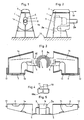
- Fig. 1 und 2
- Seitenansicht einer an einem Eckventil angebrachten Abdeckung gemäss der Erfindung,
- Fig. 3
- eine Ansicht eines Teils der Abdeckung,
- Fig. 4
- eine Seitenansicht eines Klemmringes, und
- Fig. 5
- eine weitere Ansicht des Teils nach Fig. 3.
- Wie die Fig. 3 und 5 zeigen, weist die Abdeckung zwei schalenförmige Teile 1a und 1b auf, die durch ein angeformtes Verbindungsteil 15 gelenkig miteinander verbunden sind. Die Teile 1a und 1b können unabhängig voneinander um je ein Filmscharnier 5 verschwenkt werden. Am Verbindungsteil 15 ist eine Befestigungshülse 3 mit einer seitlichen Oeffnung 4 zum Befestigen der Abdeckung am Eckventil angeordnet. Die Befestigungshülse 3 ist am freien Ende zur drehbaren Lagerung eines Klemmringes 10 stufenförmig ausgebildet. Der Klemmring 10 weist seitlich einen Schlitz 10a auf, so dass dieser Ring radial beschränkt dehnbar ist. Auf der Innenseite des Rings 10 sind zwei gegenüberliegende und axial verlaufende Rippen angebracht, die mit axialen Rillen 3a am Umfang der Befestigungshülse 3 zusammenwirken. Der Klemmring 10 und die Befestigungshülse 3 werden separat unter elastischer Dehnung auf das Eckventil aufgeschoben und nachher zusammengesetzt.
- Die schalenförmigen Teile 1a und 1b können in die in den Fig. 1 und 2 gezeigte Lage zusammengeklappt werden. In dieser Position liegen zwei Rastnocken 12 im Abstand und parallel gegenüber. Auf diese Rastnocken 12 ist ein Deckel 2 aufgerastet. Die Nocken 12 sind so dimensioniert, dass der Deckel in seiner Längsrichtung begrenzt verschiebbar ist. Dieser Deckel 2 verbindet die beiden Teile 1a und 1b fest miteinander. Um den Deckel zu lösen wird der in Richtung des Pfeiles 17 bis etwa auf seine halbe Länge nach aussen geschoben. In dieser Position kann er am vorstehenden Ende gefasst und ausgerastet werden. In der geschlossenen Position greifen zudem gestufte Ränder 13 ineinander, so dass die Teile 1a und 1b gegeneinander nicht verschoben werden können.
- Zwischen die schalenförmigen Teile 1a und 1b ist in eine Oeffnung 6 eine Blende 7 mit einer Oeffnung 8 für den Durchtritt des Eckventils 9b eingelegt. Die Blende 7 ist seitlich offen und kann unter Dehnung auf den Teil 9b aufgeschoben sowie in der Oeffnung 6 begrenzt verschoben werden.
- Um die Abdeckung am Eckventil 9 anzubringen, werden der Klemmring 10 und die Befestigungshülse 3 jeweils unter Dehnung seitlich auf das Eckventil 9 aufgeschoben. Diese Teile werden nun zusammengesetzt und der Klemmring gedreht, bis eine daran angebrachte schraubenförmig ansteigende Fläche 11 am Teil 9b des Eckventils 9 ansteht. Durch weiteres Drehen des Klemmringes wird der Verbindungsteil 15 an die Wand 14 gespannt. Nun werden die beiden Teile 1a und 1b zusammengeklappt und der Deckel 2 aufgesetzt. Die Abdeckung 1 ist wie in den Figuren 1 und 2 gezeigt damit lösbar am Eckventil 9 fixiert. Mit den genannten Handlungen in umgekehrter Reihenfolge kann die Abdeckung 1 in einfacher Weise und ohne Werkzeuge abgenommen werden.
Claims (9)
- Abdeckung für ein an einer Wand (14) befestigtes Eckventil (9), mit zwei wenigstens teilweise trennbaren schalenförmigen Teilen (1a,1b), mit ersten Mitteln (3) zum Befestigen der Abdeckung (1) und zweiten Mitteln (2,12), welche die schalenförmigen Teile (1a,1b) lösbar miteinander verbinden, dadurch gekennzeichnet, dass die ersten Mittel eine zwischen den schalenförmigen Teilen (1a,1b) angeordnete Befestigungshülse (3) aufweisen, die mit diesen Teilen (1a,1b) eine Einheit bildet und seitlich auf das Eckventil (9) aufschiebbar und an diesem fixierbar ist und die mit den beiden schalenförmigen Teilen (1a,1b) fest verbunden ist.
- Abdeckung nach Anspruch 1, dadurch gekennzeichnet, dass die beiden schalenförmigen Teile (1a,1b) über ein Gelenk (5) klappbar miteinander und mit der Befestigungshülse (3) verbunden sind.
- Abdeckung nach Anspruch 2, dadurch gekennzeichnet, dass das Gelenk im Abstand zueinander angeordnete Filmscharniere (5) aufweist, und dass zwischen diesen Scharnieren die Befestigungshülse (3) angeordnet ist.
- Abdeckung nach einem der Ansprüche 1 bis 3, dadurch gekennzeichnet, dass die Befestigungshülse (3) seitlich auf das Eckventil (9) aufsteckbar ist.
- Abdeckung nach Anspruch 4, dadurch gekennzeichnet, dass zwischen den schalenförmigen Teilen (1a,1b) desweiteren ein Teil (10) angebracht ist, das mit der Befestigungshülse (3) derart zusammenwirkt, dass die Abdeckung (1) gegen die Wand (14) gespannt werden kann.
- Abdeckung nach Anspruch 5, dadurch gekennzeichnet, dass das Teil ein Klemmring (10) ist und an einem die schalenförmigen Teile (1a,1b) mit der Befestigungshülse (3) verbindenden Verbindungsteil (15) drehbar gelagert ist und eine in Längsrichtung des senkrecht zur Wand (14) verlaufenden Teils des Eckventils schraubenförmig ansteigende Fläche (11) aufweist, derart, dass diese Fläche (11) durch Drehen des Klemmrings (10) an den parallel zur Wand (14) verlaufenden Teil des Eckventils (9) anlegbar und das Verbindungsteil (15) an die Wand (14) klemmbar ist.
- Abdeckung nach einem der Ansprüche 1 bis 6, dadurch gekennzeichnet, dass die zweiten Mittel (2,12) einen Deckel (2) aufweisen, der auf die schalenförmigen Teile (1a,1b) lösbar aufgesetzt ist.
- Abdeckung nach einem der Ansprüche 1 bis 7, dadurch gekennzeichnet, dass zwischen den schalenförmigen Teilen (1a,1b) eine Oeffnung (6) angeordnet ist, und dass in diese Oeffnung (6) eine Blende (7) eingesetzt ist, die eine weitere Oeffnung (8) für den Durchgang eines parallel zur Wand (14) verlaufenden Teils des Eckventils (9) aufweist.
- Abdeckung nach einem der Ansprüche 1 bis 8, dadurch gekennzeichnet, dass die Abdeckung (1) aussen von der Wand (14) weg nach vorne hin keilförmig verjüngt ist.
Priority Applications (1)
| Application Number | Priority Date | Filing Date | Title |
|---|---|---|---|
| AT90810162T ATE94956T1 (de) | 1989-03-10 | 1990-03-02 | Abdeckung fuer ein an einer wand befestigtes eckventil. |
Applications Claiming Priority (2)
| Application Number | Priority Date | Filing Date | Title |
|---|---|---|---|
| CH902/89 | 1989-03-10 | ||
| CH90289 | 1989-03-10 |
Publications (3)
| Publication Number | Publication Date |
|---|---|
| EP0387199A2 EP0387199A2 (de) | 1990-09-12 |
| EP0387199A3 EP0387199A3 (en) | 1990-12-12 |
| EP0387199B1 true EP0387199B1 (de) | 1993-09-22 |
Family
ID=4197842
Family Applications (1)
| Application Number | Title | Priority Date | Filing Date |
|---|---|---|---|
| EP90810162A Expired - Lifetime EP0387199B1 (de) | 1989-03-10 | 1990-03-02 | Abdeckung für ein an einer Wand befestigtes Eckventil |
Country Status (3)
| Country | Link |
|---|---|
| EP (1) | EP0387199B1 (de) |
| AT (1) | ATE94956T1 (de) |
| DE (1) | DE59002785D1 (de) |
Families Citing this family (5)
| Publication number | Priority date | Publication date | Assignee | Title |
|---|---|---|---|---|
| DE9010851U1 (de) * | 1990-07-21 | 1990-09-27 | Hans Grohe Gmbh & Co Kg, 7622 Schiltach | Sanitärarmatur mit einem Eckventil |
| AT631U1 (de) * | 1994-04-08 | 1996-02-26 | Vogel & Noot Waermetechnik Ag | Ventilabdeckung |
| DE19600286C2 (de) * | 1996-01-05 | 2001-03-29 | Festo Ag & Co | Kompaktregelventil |
| DE102004009534A1 (de) * | 2004-02-21 | 2005-11-10 | Böhm, Lothar | Armaturenkappe in rund ausgelagerter/dreiecksabgeflachter Form oder in rund auf oval einseitiger Form |
| ITMI20081671A1 (it) * | 2008-09-22 | 2010-03-23 | F E V S R L | Struttura di apparecchio sanitario per la distribuzione di acqua, costituito da un rubinetto per gruppo vasca o lavabo o simile. |
Family Cites Families (1)
| Publication number | Priority date | Publication date | Assignee | Title |
|---|---|---|---|---|
| US4301828A (en) * | 1979-12-17 | 1981-11-24 | Martin Jr Timothy J | Protective cover device |
-
1990
- 1990-03-02 AT AT90810162T patent/ATE94956T1/de not_active IP Right Cessation
- 1990-03-02 DE DE90810162T patent/DE59002785D1/de not_active Expired - Fee Related
- 1990-03-02 EP EP90810162A patent/EP0387199B1/de not_active Expired - Lifetime
Also Published As
| Publication number | Publication date |
|---|---|
| EP0387199A3 (en) | 1990-12-12 |
| DE59002785D1 (de) | 1993-10-28 |
| EP0387199A2 (de) | 1990-09-12 |
| ATE94956T1 (de) | 1993-10-15 |
Similar Documents
| Publication | Publication Date | Title |
|---|---|---|
| EP0470330B1 (de) | Ansaugluftfilter für die Verbrennungskraftmaschine eines Fahrzeugs | |
| DE2933463C3 (de) | Mehrteiliger Fräser | |
| DE69006985T2 (de) | Befestigungseinrichtung. | |
| DE102015103435B4 (de) | Toilettendeckel mit einem leicht demontierbaren Kindersitzring | |
| DE19621432A1 (de) | Baugruppe zur Verbindung eines Betätigungsorgans mit einem Drehabsperrorgan | |
| DE4425491A1 (de) | Aufsteck-Fixierelement zum Eingriff in eine Schraube | |
| EP0471989B1 (de) | Rohrschelle | |
| DE4018655C2 (de) | Luftfilter | |
| EP0760445A1 (de) | Rohrschelle | |
| EP0153677B1 (de) | Selbstschliessender Kraftstoffbehälterverschluss | |
| CH673689A5 (de) | ||
| EP0387199A2 (de) | Abdeckung für ein an einer Wand befestigtes Eckventil | |
| DE60209694T2 (de) | Einlassystem für einen zentralen Staubsauger | |
| DE4125341B4 (de) | Zweiteiliges Luftfiltergehäuse | |
| DE69609057T2 (de) | Eine Vorrichtung für die Befestigung einer Stange auf eine Abstützung, wie zum Beispiel eine Mauer | |
| DE1586865A1 (de) | Zentrale Verriegelungsvorrichtung fuer zur Aufnahme von Spulen,insbesondere Tonbandspulen,bestimmte kreisfoermige Buechsen | |
| DE3539576C2 (de) | ||
| DE202012103312U1 (de) | Ablaufgarnitur für eine sanitäre Wanne oder Duschtasse und dafür hergerichtete sanitäre Wanne oder Duschtasse | |
| EP0298270B1 (de) | Arbeitsgerät, wie Gartengerät, Feldgerät, Putzgerät oder dergleichen | |
| DE7011866U (de) | Aus blech bestehendes verbindungsstueck. | |
| DE4419407A1 (de) | Armlehne für Fahrzeugsitze | |
| EP0898919B1 (de) | Verstellelement für eine Duschvorrichtung oder dgl. | |
| EP1162337A2 (de) | Scharnier, insbesondere für ein Fahrzeug | |
| DE3513538A1 (de) | Stopfen | |
| DE3243506A1 (de) | Schmutzsauger mit filterpatrone |
Legal Events
| Date | Code | Title | Description |
|---|---|---|---|
| PUAI | Public reference made under article 153(3) epc to a published international application that has entered the european phase |
Free format text: ORIGINAL CODE: 0009012 |
|
| AK | Designated contracting states |
Kind code of ref document: A2 Designated state(s): AT BE CH DE DK FR IT LI LU NL |
|
| PUAL | Search report despatched |
Free format text: ORIGINAL CODE: 0009013 |
|
| AK | Designated contracting states |
Kind code of ref document: A3 Designated state(s): AT BE CH DE DK FR IT LI LU NL |
|
| RHK1 | Main classification (correction) |
Ipc: F16K 27/12 |
|
| 17P | Request for examination filed |
Effective date: 19910111 |
|
| 17Q | First examination report despatched |
Effective date: 19920807 |
|
| GRAA | (expected) grant |
Free format text: ORIGINAL CODE: 0009210 |
|
| AK | Designated contracting states |
Kind code of ref document: B1 Designated state(s): AT BE CH DE DK FR IT LI LU NL |
|
| PG25 | Lapsed in a contracting state [announced via postgrant information from national office to epo] |
Ref country code: DK Effective date: 19930922 |
|
| REF | Corresponds to: |
Ref document number: 94956 Country of ref document: AT Date of ref document: 19931015 Kind code of ref document: T |
|
| ITF | It: translation for a ep patent filed | ||
| REF | Corresponds to: |
Ref document number: 59002785 Country of ref document: DE Date of ref document: 19931028 |
|
| ET | Fr: translation filed | ||
| PG25 | Lapsed in a contracting state [announced via postgrant information from national office to epo] |
Ref country code: LU Free format text: LAPSE BECAUSE OF NON-PAYMENT OF DUE FEES Effective date: 19940331 |
|
| PLBE | No opposition filed within time limit |
Free format text: ORIGINAL CODE: 0009261 |
|
| STAA | Information on the status of an ep patent application or granted ep patent |
Free format text: STATUS: NO OPPOSITION FILED WITHIN TIME LIMIT |
|
| 26N | No opposition filed | ||
| PGFP | Annual fee paid to national office [announced via postgrant information from national office to epo] |
Ref country code: FR Payment date: 19960208 Year of fee payment: 7 |
|
| PGFP | Annual fee paid to national office [announced via postgrant information from national office to epo] |
Ref country code: BE Payment date: 19960216 Year of fee payment: 7 |
|
| PGFP | Annual fee paid to national office [announced via postgrant information from national office to epo] |
Ref country code: NL Payment date: 19960330 Year of fee payment: 7 |
|
| PGFP | Annual fee paid to national office [announced via postgrant information from national office to epo] |
Ref country code: AT Payment date: 19970213 Year of fee payment: 8 |
|
| PGFP | Annual fee paid to national office [announced via postgrant information from national office to epo] |
Ref country code: CH Payment date: 19970214 Year of fee payment: 8 |
|
| PGFP | Annual fee paid to national office [announced via postgrant information from national office to epo] |
Ref country code: DE Payment date: 19970224 Year of fee payment: 8 |
|
| PG25 | Lapsed in a contracting state [announced via postgrant information from national office to epo] |
Ref country code: BE Effective date: 19970331 |
|
| BERE | Be: lapsed |
Owner name: GEBERIT A.G. Effective date: 19970331 |
|
| PG25 | Lapsed in a contracting state [announced via postgrant information from national office to epo] |
Ref country code: NL Effective date: 19971001 |
|
| PG25 | Lapsed in a contracting state [announced via postgrant information from national office to epo] |
Ref country code: FR Free format text: LAPSE BECAUSE OF NON-PAYMENT OF DUE FEES Effective date: 19971128 |
|
| NLV4 | Nl: lapsed or anulled due to non-payment of the annual fee |
Effective date: 19971001 |
|
| REG | Reference to a national code |
Ref country code: FR Ref legal event code: ST |
|
| PG25 | Lapsed in a contracting state [announced via postgrant information from national office to epo] |
Ref country code: AT Free format text: LAPSE BECAUSE OF NON-PAYMENT OF DUE FEES Effective date: 19980302 |
|
| PG25 | Lapsed in a contracting state [announced via postgrant information from national office to epo] |
Ref country code: LI Free format text: LAPSE BECAUSE OF NON-PAYMENT OF DUE FEES Effective date: 19980331 Ref country code: CH Free format text: LAPSE BECAUSE OF NON-PAYMENT OF DUE FEES Effective date: 19980331 |
|
| REG | Reference to a national code |
Ref country code: CH Ref legal event code: PL |
|
| PG25 | Lapsed in a contracting state [announced via postgrant information from national office to epo] |
Ref country code: DE Free format text: LAPSE BECAUSE OF NON-PAYMENT OF DUE FEES Effective date: 19981201 |
|
| PG25 | Lapsed in a contracting state [announced via postgrant information from national office to epo] |
Ref country code: IT Free format text: LAPSE BECAUSE OF NON-PAYMENT OF DUE FEES;WARNING: LAPSES OF ITALIAN PATENTS WITH EFFECTIVE DATE BEFORE 2007 MAY HAVE OCCURRED AT ANY TIME BEFORE 2007. THE CORRECT EFFECTIVE DATE MAY BE DIFFERENT FROM THE ONE RECORDED. Effective date: 20050302 |