EP0383350A2 - Mehrgangnabe - Google Patents
Mehrgangnabe Download PDFInfo
- Publication number
- EP0383350A2 EP0383350A2 EP90103058A EP90103058A EP0383350A2 EP 0383350 A2 EP0383350 A2 EP 0383350A2 EP 90103058 A EP90103058 A EP 90103058A EP 90103058 A EP90103058 A EP 90103058A EP 0383350 A2 EP0383350 A2 EP 0383350A2
- Authority
- EP
- European Patent Office
- Prior art keywords
- fixed shaft
- control
- sun gears
- drive member
- transmission
- Prior art date
- Legal status (The legal status is an assumption and is not a legal conclusion. Google has not performed a legal analysis and makes no representation as to the accuracy of the status listed.)
- Granted
Links
Images


Classifications
-
- B—PERFORMING OPERATIONS; TRANSPORTING
- B62—LAND VEHICLES FOR TRAVELLING OTHERWISE THAN ON RAILS
- B62M—RIDER PROPULSION OF WHEELED VEHICLES OR SLEDGES; POWERED PROPULSION OF SLEDGES OR SINGLE-TRACK CYCLES; TRANSMISSIONS SPECIALLY ADAPTED FOR SUCH VEHICLES
- B62M11/00—Transmissions characterised by the use of interengaging toothed wheels or frictionally-engaging wheels
- B62M11/04—Transmissions characterised by the use of interengaging toothed wheels or frictionally-engaging wheels of changeable ratio
- B62M11/14—Transmissions characterised by the use of interengaging toothed wheels or frictionally-engaging wheels of changeable ratio with planetary gears
- B62M11/16—Transmissions characterised by the use of interengaging toothed wheels or frictionally-engaging wheels of changeable ratio with planetary gears built in, or adjacent to, the ground-wheel hub
-
- B—PERFORMING OPERATIONS; TRANSPORTING
- B62—LAND VEHICLES FOR TRAVELLING OTHERWISE THAN ON RAILS
- B62L—BRAKES SPECIALLY ADAPTED FOR CYCLES
- B62L5/00—Brakes, or actuating mechanisms therefor, controlled by back-pedalling
- B62L5/10—Brakes, or actuating mechanisms therefor, controlled by back-pedalling the brakes being actuated through coacting cams and balls or rollers located in the rear wheel hub
- B62L5/16—Brakes, or actuating mechanisms therefor, controlled by back-pedalling the brakes being actuated through coacting cams and balls or rollers located in the rear wheel hub the brakes being of shoe type
-
- B—PERFORMING OPERATIONS; TRANSPORTING
- B62—LAND VEHICLES FOR TRAVELLING OTHERWISE THAN ON RAILS
- B62M—RIDER PROPULSION OF WHEELED VEHICLES OR SLEDGES; POWERED PROPULSION OF SLEDGES OR SINGLE-TRACK CYCLES; TRANSMISSIONS SPECIALLY ADAPTED FOR SUCH VEHICLES
- B62M11/00—Transmissions characterised by the use of interengaging toothed wheels or frictionally-engaging wheels
- B62M11/04—Transmissions characterised by the use of interengaging toothed wheels or frictionally-engaging wheels of changeable ratio
- B62M11/14—Transmissions characterised by the use of interengaging toothed wheels or frictionally-engaging wheels of changeable ratio with planetary gears
- B62M11/18—Transmissions characterised by the use of interengaging toothed wheels or frictionally-engaging wheels of changeable ratio with planetary gears with a plurality of planetary gear units
-
- F—MECHANICAL ENGINEERING; LIGHTING; HEATING; WEAPONS; BLASTING
- F16—ENGINEERING ELEMENTS AND UNITS; GENERAL MEASURES FOR PRODUCING AND MAINTAINING EFFECTIVE FUNCTIONING OF MACHINES OR INSTALLATIONS; THERMAL INSULATION IN GENERAL
- F16D—COUPLINGS FOR TRANSMITTING ROTATION; CLUTCHES; BRAKES
- F16D41/00—Freewheels or freewheel clutches
- F16D41/24—Freewheels or freewheel clutches specially adapted for cycles
- F16D41/30—Freewheels or freewheel clutches specially adapted for cycles with hinged pawl co-operating with teeth, cogs, or the like
-
- B—PERFORMING OPERATIONS; TRANSPORTING
- B62—LAND VEHICLES FOR TRAVELLING OTHERWISE THAN ON RAILS
- B62B—HAND-PROPELLED VEHICLES, e.g. HAND CARTS OR PERAMBULATORS; SLEDGES
- B62B5/00—Accessories or details specially adapted for hand carts
- B62B5/04—Braking mechanisms; Locking devices against movement
- B62B5/048—Hub brakes; drum brakes
Definitions
- the present invention relates to a change-speed hub for use in e.g. a bicycle, and more particularly to a change-speed hub including a fixed shaft, a hub body rotatably mounted on the fixed shaft, a drive member rotatably mounted on the fixed shaft for transmitting a drive force to the hub body selectively through a plurality of transmission channels and a clutch for selecting one from the transmission channels.
- a known change-speed hub of the above-specified type includes first and second sun gears rotatable relative to a fixed shaft and having different diameters and a lock control mechanism for locking the sun gears to and releasing the same from the fixed shaft.
- the fixed shaft further includes an axially movable first control portion having a control portion for controlling a clutch element and externally operable at one distal end of the hub body and an axially movable second control portion having a control portion for activating the lock control mechanism to lock either the first or second sun gear to the fixed shaft. Accordingly, by moving the first control portion, the clutch is operated to select a desired transmission channel. Also, by moving the second control portion, one of the first and second sun gears is locked to the fixed shaft. In this way, the hub provides a plurality of speeds (Japanese published patent gazette No. 53-14820).
- the present invention attends to the above-described drawback of the prior art.
- the invention's primary object is to provide improved change-speed hub which provides a light change speed operation feel to the user because of effectively reduced load acting on the control portion of the hub.
- a change-speed hub having: a fixed shaft; a hub body rotatably mounted on the fixed shaft; a drive member rotatably mounted on the fixed shaft for transmitting a drive force to the hub body selectively through a plurality of transmission channels; a clutch for selecting one from the transmission channels; a plurality of sun gears rotatably mounted on the fixed shaft and having diameters differing from each other; a lock control mechanism for controlling locking and releasing of the sun gears relative to the fixed shaft
- the change-speed hub of the present invention is characterized in that the sun gears have axial movements thereof substantially limited and in that a control member is rotatably mounted on the fixed shaft, the control member including a first control portion for controlling the clutch and second and third control portions for activating the lock control mechanism for selectively locking the sun gears to the fixed shaft, the control member being operable externally of the hub body for providing a plurality of speeds through the selection of the transmission channel and the selection of the sun gear to be locked by the lock
- the first control portion acts to select the transmission channel while the second and third control portions act to select the sun gear to be locked by the lock control mechanism.
- the invention's change-speed hub includes the sun gears having different diameters, the lock control mechanism for controlling locking and releasing of the sun gears relative to the fixed shaft and the clutch for selecting the transmission channel from the drive member to the hub body. Yet, with above-described characterized construction, the selection of the transmission channel and also that of the sun gears to be locked to the fixed shaft can both be effected by the very simple rotational operation of the control member. Consequently, the invention's change-speed hub can provide light operational feel and also reliable and error-free operation.
- a braking construction used in a change-speed hub having a fixed shaft, a hub body rotatably mounted on the fixed shaft, a drive member rotatably mounted on the fixed shaft for transmitting a drive force to the hub body selectively through a plurality of transmission channels, clutches for selecting one from the transmission channels and a braking mechanism for releasing engagement between the drive member and the hub body through reverse rotation of the drive member relative to a driving direction, the mechanism including a braking member for braking rotation of said hub body
- the braking construction of the present invention is characterized in that the releasing action of the engagement between the drive member and the hub body is effected through an interaction of a plurality of transmission claws supported to the drive member.
- the above-described braking constructon achieves an easy operation while maintaining the light change-speed operation feel of the hub body rotation.
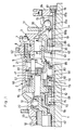
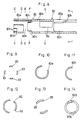
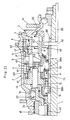
- Fig. 1 shows a five-speed, change-speed hub capable of providing two high speeds, one middle speed and two low speeds for use in a bicycle.
- This change-speed hub mainly includes a fixed shaft 1 to be fixed to a bicycle frame, a cylindrical hub body 2 rotatably mounted on the fixed shaft 1, a drive member rotatably mounted on the fixed shaft 1, a cylindrical gear carrier 4 accommodated in the hub body 2 and carrying planet gears meshing with sun gears to be described later, a ring gear 5 accommodated in the hub body 2 and having an internal gear 51 meshable with the planet gears, a relay member 6 for relaying a rotational force from the drive member 3 to the gear carrier 4, a first transmission claw 7 projectably and retractably disposed between the drive member 3 and the relay member 6, a second transmission claw 8 projectably and retractably disposed between the drive member 3 and the ring gear 5, a third transmission claw 9 projectably and retractably disposed between the hub body 2 and the ring gear 5 and a fourth transmission claw 10 projectably and retractably
- a key 30 axially movable within an elongated slot extending radially.
- a chain gear 31 engageable with a drive chain of the bicycle.
- the second transmission claw 8 At a longitudinal intermediate position of the drive member 3, there is supported the second transmission claw 8.
- the first transmission claw 7 is supported to the inner peripheral face of the drive member 3, with the claw 7 being urged toward the relay member 6 by means of a claw spring.
- the second transmission claw 8 is urged to the inner peripheral face of the ring gear 5 by means of a claw spring.
- a ratchet 52 engageable with the second transmission claw 8.
- the internal gear 51 On the opposite side of the inner peripheral face of the ring gear 5, there is provided the internal gear 51.
- the third transmission claw 9 is supported, with the claw 9 being urged towards the ratchet 21 by means of a claw spring.
- a ratchet 62 engageable with the first transmission claw 7.
- a control face which comes into contact with a leg portion of the third transmission claw 9 opposed to its claw portion during the axial movement for controlling the third transmission claw 9.
- the clutch 20 is constructed as a cylindrical member having a large diameter portion and a small diameter portion divided across a stepped portion. On a face of the large diameter portion opposing to the transmission claw 7, there is formed a cam face. Also, on an inner periphery of the small diameter portion, there provided a stopper portion engageable with the key 30 for stopping rotation.
- the fixed shaft 1 rotatably mounts, at axially different intermediate positions thereof, a first sun gear 11 and a second sun gear 12. Both the sun gears have a cylindrical shape and define teeth on its outer periphery and the first sun gear 11 is larger in diameter than the second sun gear 12.
- the gear carrier 4 rotatably mounts a first planet gear 13 meshable with the first sun gear 11 and a second planet gear 14 meshable with the second sun gear 12, with the first planet gear 13 being smaller in diameter than the second planet gear 14.
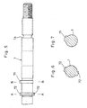
- a first regulating projection 71 and a second regulating projection 72 At axially different positions of the outer peripheral face of the fixed shaft 1, as illustrated in Figs. 5 through 7, there are provided a first regulating projection 71 and a second regulating projection 72.
- first lock claws 73 engageable with the first regulating projection 71, with the two claws 73 of each pair having leading ends directed in opposite directions.
- second lock claws 74 engageable with the second regulating projection 72, with the two claws 74 of each pair having leading ends directed in opposite directions.
- control member 80 On the outer periphery of the fixed shaft 1, there is rotatably mounted a control member 80 which is operable externally of the hub body 2.
- This control member 80 includes a first control portion 81 for controlling the clutch 20, a second control portion 82 for causing the lock control mechanism 70 to lock the first sun gear 11 to the fixed shaft 1 and a third control portion 83 for locking the second sun gear 12 to the fixed shaft 1. Then, with a rotational operation on this control member 80, both the selection of the transmission channel and also that of the sun gears to be locked to the fixed shaft can be readily effected for providing a plurality of speeds.
- first sun gear 11 and the second sun gear 12 are rotatable relative to each other.
- the lock claws 73 and 74 supported to the inner peripheral faces of the respective sun gears 11, 12 are urged to the outer peripheral face of the fixed shaft 1 by means of the claw springs. Incidentally, these two pairs of the lock claws 73 and 74 can be substituted by one pair for each.
- the first planet gear 13 and the second planet gear 14 are formed integrally with each other and are supported to the gear carrier 4 through a single common shaft. Further, the first planet gear 13 is meshed with the internal teeth 51 of the ring gear 5.
- the control member 80 has a length extending from one distal end of the fixed shaft 1 to a portion of the shaft 1 carrying the second regulating projection 72. Also, the control member 80 is loosely, i.e. rotatably mounted on the fixed shaft 1.
- control member 80 On a distal end of the control member 80, there is provided a disc-shaped control portion 84 having a stopper portion for stopping an end of a change-speed control cable. At the other end of the member 80, there are provided the second and third control portions 82 and 83. Moreover, at intermediate positions of the control member 80, there are provided the first control portion 81 and an elongated inserting slot 85 for receiving the key 30.
- the first control portion 81 includes a first cam face 81a, a second cam face 81b continuous with the first cam face, a third cam face 81d continuous with the second cam face 81b through a stepped portion 81c therebetween, and a fourth cam face 81e, with the first through fourth cam faces and the stepped portion being dispersed peripherally in said order.
- the first cam face 81a is formed normal to the axis of the fixed shaft 1. Further, this first control portion 81 is formed independently of a cylindrical body 80a having the control portion.
- control portion 81 is formed as a cylindrical member including a radially extending, disc-shaped flange portion and a cylindrical portion extending axially from one end of the flange portion.
- This cylindrical control portion 81 includes, in its inner peripheral face, a pair of opposed engaging grooves 86, 86 engageable with fork portions 80g (to be described later) of the cylindrical body 80a, such that the first control portion 81 is unrotatably connected with the cylindrical body 80a.
- the second and third control portions 82 and 83 are formed as axially extending projections comprised of partial cutouts of the cylindrical body 80a. More particularly, as illustrated in Fig. 2 and also in Figs. 8 through 12, at the leading end of the cylindrical body 80a, there are formed a peripheral groove 80b extending in the peripheral direction and a plurality of axial grooves 80C extending from the peripheral groove 80b toward the control portion 84. Thus, the projecting portions between these grooves 80b and 80c constitute the second control portion 82. On the other hand, there are formed a plurality of axial grooves 80d extending from the leading edge of the cylindrical body 80a to the control portion 84. Then, the projections between these grooves 80d constitute the third control portion 83.
- a communicating groove 80e extending from the peripheral groove 80b to the leading edge, so that the first regulating projection 71 is positioned in the peripheral groove 80b. Then, as the peripheral groove 80b receives the first regulating projection 71, as shown in Figs. 2 and 3, the first regulating projection 71 and the second control portion 82 are axially aligned with each other. Further, as the second regulating projection 72 is positioned externally of the leading edge of the cylindrical body 80a, as shown in Figs. 2 and 3, the second regulating projection 72 and the third control portion 83 are axially aligned with each other.
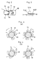
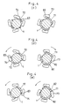
- the first lock claws 73 are engageable with the first regulating projection 71 and the second control portion 82; whereas, the second lock claws 74 are engageable with the second regulating projection 72 and the third control portion 83. Then, by varying the peripheral positions of the second and third control portions 82 and 83 relative to the respective regulating projections 71 and 72, the respective lock claws 73 and 74 are controlled as illustrated in Figs. 4(a) through 4(e).
- control member 80 On the side of the control portion 84, as shown in Figs. 8, 13 and 14, the control member 80 is forked shaped. Specifically, the control member 80 includes, at this portion thereof, a pair of axially extending slits 80f and a pair of the fork portions 80g formed between the slits 80f. Further, at an intermediate inner portion of each fork portion 80g, there is formed an abutment 80h which comes into abutment against a stepped portion 1a formed on the fixed shaft 1 for limiting the axial movement of the control member 80.
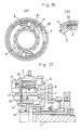
- a ball pushing element 15 is provided for supporting the drive member 3 to the fixed shaft 1.
- this ball pushing element 15 In an inner peripheral face of this ball pushing element 15, as shown in Fig. 16, there is formed a peripherally extending guide groove 15a. Then, as the fork portion 80g is inserted into the guide groove 15 along the engaging groove 86, the control member 80 is held rotatable relative to the ball pushing element 15. Incidentally, the ball pushing element 15 is axially slidably yet unrotatably fitted on the fixed shaft 1.
- the control portion 84 is formed independently of the cylindrical body 80a. On the inner peripheral face of the control portion 84, as shown in Fig. 18, there are a pair of projections 87 including engaging grooves 87a into which the leading ends of the fork portions 80g are engaged. Further, on the inner side of this control portion 84, there is provided a spacer 16 having a peripheral guide groove 16a for guiding the projection 87 (see Fig. 17), so that this spacer 16 is only axially movable relative to the fixed shaft 1.
- a projectable/retractable fifth transmission claw 17 for transmitting rotational force of the drive member 3 through the relay member 6 to the gear carrier 4 when the drive member 3 is rotated in the reverse direction.
- the hub body 2 includes, in its inner periphery, a braking face 23.
- the gear carrier 4 includes, in its end periphery, a cam face 42.
- a reference numeral 19 denotes a return spring for returning the control member 80.
- a numeral 40 denotes a return spring for returning the clutch 20. By means of this return spring 40, the clutch 20 is engaged with the first control portion 81 via the key 30.
- a reference numeral 50 denotes a return spring for returning the relay member 6.
- a numeral 60 denotes a control ring unrotatably supported to the inner peripheral face of the hub body 2 and for depressing the third transmission claw 9 when the drive member 3 is rotated in the reverse direction.
- the change-speed hub is in the highest speed stage.
- the clutch 20 and the relay member 60 are located at their rightmost positions.
- the first lock claws 73 of the lock control mechanism 70 are controlled by the second control portion 82 so that the claws 73 are engaged with the first regulating projection 71 (see Fig. 4(a)) thereby to lock the first sun gear 11 against rotation.
- the first transmission claw 7 engages with the ratchet 62 of the relay member 6
- the power from the drive member 3 is transmitted via the first transmission claw 7 and the relay member 6 to the gear carrier 4.
- this power transmitted to the gear carrier 4 is further transmitted via the first planet gear 13 to the ring gear 5 and the third transmission claw 9 engaged with the first ratchet 21 to consequently the hub body 2 for rotating the same at the top speed.
- the second planet gear 14 is rotated in the same direction as the first planet gear 13.
- the rotational speed transmitted from the second planet gear 14 to the second sun gear 12 is lower than that transmitted from the first planet gear 13 to the ring gear 5, as illustrated in Fig. 14(a)
- the second sun gear 12 is rotated in the opposite direction to that of the force acting on the first sun gear 11, the second sun gear 12 is not locked.
- the second transmission claw 8 becomes engaged with the ratchet 52 of the ring gear 5.
- the rotational speed transmitted from the gear carrier 4 to the ring gear 5 is higher than that transmitted from the drive member 3 via the second transmission claw 8 to the ring gear 5, the second transmission claw 8 only slides.
- the control member 80 For effecting a change speed operation from the above-described top speed stage to a second highest speed stage, the control member 80 is rotated so that, as illustrated in Fig. 4(b), the third control portion 83 causes the second lock claw 74 of the lock control mechanism 70 to come into engagement with the second regulating projection 72 thereby to lock the second sun gear 12 againt rotation. Further, the second control portion 82 acts to release the engagement between the first lock claw 73 and the first regulating projection 71 thereby to release the locked condition of the first sun gear 11.
- the power transmitted through the first transmission claw 7, the relay member 6 and the gear carrier 4 is further transmitted via the second planet gear 14, the ring gear 5 and the third transmission claw 9 to consequently the hub body for rotating the same at the second highest speed.
- the key 30 engaged with the first control portion 81 effects only a peripheral displacement along the first cam face 81a of the first control portion 81 and the clutch 20 does not effect axial movement.
- the second transmission claw 8 comes into engagement with the ratchet 52 of the ring gear 5.
- the rotational speed transmitted from the gear carrier 4 to the ring gear 5 is higher than that tranmitted from the drive member 3 via the second transmission claw 8 to the ring gear 5, similarly to the foregoing case, the second transmission claw 8 only slides.
- the control member 80 is further rotated for causing the second cam face 81b of the first control portion 81 to move the clutch 20 toward the gear carrier 4 so that the cam face of the clutch 20 depresses the first transmission claw 7 to break the power transmission from the drive member 3 to the relay member 6. Accordingly, the power of the drive member 3 is transmitted via the second transmission claw 8, the ring gear 5 and the third transmission claw 9 to consequently the hub body 2 for rotating the same at the middle speed.
- the third control portion 83 causes the second lock claw 74 of the lock control mechanism 70 to come into engagement with the second regulating projection 72 thereby to lock the second sun gear 12 against rotation.
- the second control portion 82 acts to release the engagement between the first lock claw 73 and the first regulating projection 71, whereby the locked condition of the first sun gear 11 is released.
- the intermediate stepped portion of the clutch 20 is placed in contact with the terminal edge of the relay member 6.
- the control member 80 is further rotated to cause the third cam face 81d of the first control portion 81 to move the clutch 20 further toward the gear carrier 4.
- the third control portion 83 causes the second lock claw 74 of the lock control mechanism 70 to come into engagement with the second regulating projection 72 thereby to lock the second sun gear 12 against rotation.
- the second control portion 82 acts to release the engagement between the first lock claw 73 and the first regulating projection 71 thereby to release the first sun gear 11.
- the relay casing 6 moves toward the gear carrier 4 and the outer peripheral control face of this relay member 6 depresses the third transmission claw 9 to break the power transmission from the ring gear 5 to the hub body 2.
- the power of the drive member 3 is transmitted via the second transmission claw 8, the ring gear 5, the second planet gear 14, the gear carrier 4 and the fourth transmission claw 10 consequently to the hub body 2 for rotating the same at the second lowest speed.
- the first planet gear 13 rotates in the same direction as the second planet gear 14. However, since the rotational speed transmitted from this first planet gear 13 to the first sun gear 11 is lower than that transmitted from the ring gear 5 to the second planet gear 14, the first planet gear 13 rotates in the opposite direction to that of the force acting on the second sun gear 12, whereby the first sun gear 11 is not locked.
- the control member 80 is further rotated to cause the second control portion 82, as illustrated in Fig. 4(e), to bring the first lock claw 73 of the lock control mechanism 70 into engagement with the first regulating projection 71 thereby to lock the first sun gear 11 against rotation.
- the third control portion 83 acts to release the engagement between the second lock claw 74 and the second regulating projection 72 thereby to release the second sun gear 12. Accordingly, the power transmitted from the drive member 3 via the second transmission claw 8 to the ring gear 5 is further transmitted via the first planet gear 13, the gear carrier 4 and the fourth transmission claw 10 consequently to the hub body 2 for rotating the same at the lowest speed.
- the key 30 engaged with the first control portion 81 effects only a peripheral displacement along the fourth cam face 81e continous with the third cam face 81d of the first control portion 81 and the clutch 20 does not move in the axial direction.
- a circle mark denotes an active state of each claw
- a cross mark denotes an inactive state of the claw where the claw is released from engagement by the clutch 20 and the control portions 81 through 83.
- a rectangular mark denotes a partial engagement of the claw where the claw is only partially engaged in the power transmission and effects a sliding movement due to a speed difference.
- the change-speed hub is designed to provide the five speeds of the two high speeds, the middle speed and the two low speeds.
- the hub can be designed to provide three speeds of two high speeds and one middle speed or of two low speeds and one middle speed or to provide four speeds of two high speeds and two low speeds.
- sun gears In the foregoing embodiment, two sun gears are employed. Instead, the specific number of sun gears can vary conveniently.
- control member 80 by the control portion 84 are effected from one direction in the foregoing embodiment. Alternately, it is also conceivable for the operations to be effected from the two opposite directions, i.e. the right and left directions.
- the operations for this modified arrangement, for example, in Fig. 1, it is conceivable to arrange so that the lock claw 73 of the first sun gear 11 is controlled by the control portion disposed at the right side of Fig. 1 while the lock claw 74 of the second sun gear 12 is controlled by the further control portion disposed at the left side of Fig. 1.
- lock claws 73 and 74 are supported respectively to the first and second sun gears 11 and 12.
- these lock claws can be supported respectively to the fixed shaft 1.
- the control operations of these lock claws relative to the sun gears are effected by means of sleeves 80i and 80j provided to the control member 80, respectively.
- the change speed operations by using the control portion can vary in many other ways than those described in the foregoing embodiment.
- the change speed operations can be effected by operating a control bar 89 along the fixed shaft 1.
- the control bar 89 acts in place of the first control portion 81. Then, by moving this control bar 89 along the axis of the fixed shaft 1, two separate clutches 92 are selectively moved for operating the control member 80.
- a rear portion 92a of the clutch 92 is pushed via the key 30 and then a front portion 92b having a cam face of the clutch 92 and directely connected with the control member 80 is rotated. That is, this front portion 92b when pushed by the clutch rear portion 92a rotates about the fixed shaft 1 together with the control member 80.
- control bar 89 The above axial operation of the control bar 89 is carried out by the user's operation of an unillustrated change-speed lever directly connected via a control cable with a bell crank (not shown) for pushing and pulling the control bar 89. Then, when the control bar 89 is pushed, the clutch 92 is pushed via the key 30 and then the control member 80 is rotated.
- the control portion 84 such as illustrated in Fig. 1 is not necessary.
- the user can effect the change speed operations by such straight line motions rather than the rotary motions, the user can benefit from greater easiness in the operations.
- the construction of the ball pushing element 15 can also vary in many ways.
- the element 15 includes a ball receiving face in its inclinded outer peripheral face and a plurality of balls are peripherally dispersed and received in the receiving face so that the balls per se are movable in the peripheral direction.
- the reverse rotation of the drive member 3 causes the fifth transmission claw 17 as the one transmission claw to come into contact with the second transmission claw 8 supported to the drive member 3 as the other transmission claw for depressing this second transmission claw 8 thereby to break the power transmission from the drive member 3 to the ring gear 5.
- this operation for breaking the power transmission between the drive member 3 and the ring gear 5 can be carried out in many other ways.
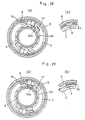
- a claw cage 91 is attached to an intermediate portion on the outer peripheral face of the drive member 3 and also a slide spring 93 is attached to the ring gear 5. So that, the claw cage 91 is moved via the fifth transmission claw 17 to come into contact with the second transmission claw 8 for depressing the same.
- the second transmission claw 8 is returned in the following manner. That is, when the drive member 3 is rotated in the forward direction, i.e. the driving direction, this drive member 3 per se effects free rotation relative to the ring gear 5. However, as shown in Figs. 25 and 26, since the claw cage 91 is unmovable because of the slide spring 93 fitted on the ring gear 5, there occurs mutual rotation between the claw cage 91 and the drive member 3 thereby to retrun the second transmission claw 8. Incidentally, when the drive member 3 and the ring gear 5 are rotated relative to each other as in the high speed stages, the claw cage 91 is placed in abutment against the drive member 3 and therefore the slide spring 93 slides relative to the ring gear 5.
- the slide spring 93 is fitted on the relay member 6 so as to limit movement of the claw cage 94 having a guide portion 94a projecting from the leading end of its claw portion.
- This construction effects the same functions as that shown in Fig. 24.
- the drive member 3 when the drive member 3 is rotated in the braking, i.e. reverse direction, the drive member 3 effects a free rotation relative to the relay member 6.
- the claw cage 94 since the claw cage 94 has its movement limited by the slide spring 93, the cage 94 is rotated ralative to the drive member 3. Accordingly, the fifth transmission claw 17, as shown in Fig. 29(a), causes the drive member 3 to come into engagement with the relay member 6 while the second transmission claw 8, as shown in Fig.
- the slide spring 93 is fitted on the relay member 6. Alternately, as shown in Fig. 24, the slide spring 93 can be fitted on the ring gear 5.
Landscapes
- Engineering & Computer Science (AREA)
- Mechanical Engineering (AREA)
- Chemical & Material Sciences (AREA)
- Combustion & Propulsion (AREA)
- Transportation (AREA)
- General Engineering & Computer Science (AREA)
- Structure Of Transmissions (AREA)
Priority Applications (1)
| Application Number | Priority Date | Filing Date | Title |
|---|---|---|---|
| EP93104353A EP0549570B1 (de) | 1989-02-17 | 1990-02-16 | Mehrgangnabe |
Applications Claiming Priority (2)
| Application Number | Priority Date | Filing Date | Title |
|---|---|---|---|
| JP39099/89 | 1989-02-17 | ||
| JP1039099A JP2930315B2 (ja) | 1989-02-17 | 1989-02-17 | 自転車用内装変速機 |
Related Child Applications (2)
| Application Number | Title | Priority Date | Filing Date |
|---|---|---|---|
| EP93104353A Division EP0549570B1 (de) | 1989-02-17 | 1990-02-16 | Mehrgangnabe |
| EP93104353.3 Division-Into | 1993-03-17 |
Publications (3)
| Publication Number | Publication Date |
|---|---|
| EP0383350A2 true EP0383350A2 (de) | 1990-08-22 |
| EP0383350A3 EP0383350A3 (de) | 1991-03-13 |
| EP0383350B1 EP0383350B1 (de) | 1995-06-07 |
Family
ID=12543629
Family Applications (2)
| Application Number | Title | Priority Date | Filing Date |
|---|---|---|---|
| EP90103058A Expired - Lifetime EP0383350B1 (de) | 1989-02-17 | 1990-02-16 | Mehrgangnabe |
| EP93104353A Expired - Lifetime EP0549570B1 (de) | 1989-02-17 | 1990-02-16 | Mehrgangnabe |
Family Applications After (1)
| Application Number | Title | Priority Date | Filing Date |
|---|---|---|---|
| EP93104353A Expired - Lifetime EP0549570B1 (de) | 1989-02-17 | 1990-02-16 | Mehrgangnabe |
Country Status (4)
| Country | Link |
|---|---|
| US (1) | US5078664A (de) |
| EP (2) | EP0383350B1 (de) |
| JP (1) | JP2930315B2 (de) |
| DE (2) | DE69029148T2 (de) |
Cited By (21)
| Publication number | Priority date | Publication date | Assignee | Title |
|---|---|---|---|---|
| DE4142867A1 (de) * | 1990-12-28 | 1992-07-02 | Shimano Kk | Geschlossene vorrichtung mit mehreren drehzahlstufen mit planetengetriebe fuer fahrraeder |
| DE4402344C1 (de) * | 1994-01-27 | 1995-03-16 | Fichtel & Sachs Ag | Steuereinrichtung für Klinkengesperre für Fahrrad-Mehrgangantriebsnaben |
| EP0693419A3 (de) * | 1994-07-23 | 1996-03-06 | Fichtel & Sachs Ag | |
| DE4143603C2 (de) * | 1990-12-28 | 1998-08-27 | Shimano Kk | Geschlossene Gangschaltvorrichtung mit mehreren Drehzahlstufen mit Planetengetriebe für Fahrräder |
| WO1998052818A1 (de) | 1997-05-16 | 1998-11-26 | Bernhard Rohloff | Mehrgang-getriebe für fahrräder |
| EP0834685A3 (de) * | 1996-09-24 | 2000-05-24 | Shimano Inc. | Schalteinrichtung für ein Fahrradgetriebe |
| DE10030959A1 (de) * | 2000-06-24 | 2002-01-03 | Sram De Gmbh | Mehrgangschaltnabe |
| EP1060980A3 (de) * | 1999-06-17 | 2002-07-10 | SRAM Deutschland GmbH | Schalteinrichtung für eine Mehrgangnabe für ein Fahrrad |
| DE10118645A1 (de) * | 2001-04-14 | 2002-10-17 | Sram De Gmbh | Einleitung und Übertragung der Schaltbewegung in ein Fahrradgetriebe |
| KR20040022467A (ko) * | 2002-09-07 | 2004-03-16 | 송승희 | 전기자전거의 자동변속장치 |
| EP1323627A3 (de) * | 2001-12-27 | 2005-09-07 | Shimano Inc. | Fahrradantriebsnabe mit Leistungsregelung für eine Hilfsschaltvorrichtung |
| EP1323626A3 (de) * | 2001-12-27 | 2005-09-14 | Shimano Inc. | Mehrteiliger Planetenradträger für eine Fahrradantriebsnabe |
| DE102004034113A1 (de) * | 2004-07-15 | 2006-02-09 | Sram Deutschland Gmbh | Getriebenabe mit Bremseinrichtung |
| EP1849700A1 (de) * | 2006-04-28 | 2007-10-31 | Shimano Inc. | Mehrgangnabe mit Planetengetriebe |
| US7670251B2 (en) | 2006-04-28 | 2010-03-02 | Shimano Inc. | Bicycle hub gearbox |
| EP1958866A3 (de) * | 2007-02-14 | 2010-09-15 | Shimano Inc. | Nabenkonstruktion eines Fahrrads |
| DE102009056206A1 (de) | 2009-11-28 | 2011-06-01 | Sram Deutschland Gmbh | Mehrgang-Getriebenabe für Fahrräder |
| NL2007564A (nl) * | 2010-10-23 | 2012-04-24 | Sram De Gmbh | Activeringsmechaniek voor een meervoudige-fietsaandrijvingsnaaf. |
| DE102012200829A1 (de) | 2012-01-20 | 2013-07-25 | Sram Deutschland Gmbh | Fahrradgetriebe, insbesondere in Form einer Mehrgang-Getriebenabe |
| EP2379402B2 (de) † | 2008-12-22 | 2017-08-23 | Pinion GmbH | Getriebeeinheit |
| DE102018104692A1 (de) | 2018-03-01 | 2019-09-05 | Pinion Gmbh | Kupplungsanordnung und Getriebeeinheit für ein per Muskelkraft antreibbares Fahrzeug |
Families Citing this family (41)
| Publication number | Priority date | Publication date | Assignee | Title |
|---|---|---|---|---|
| DE69202657D1 (de) * | 1991-09-09 | 1995-06-29 | Shimano Kk | Selbstständige Fahrradgangschaltung. |
| DE4203509A1 (de) * | 1992-02-07 | 1993-08-12 | Fichtel & Sachs Ag | Mehrgang-antriebsnabe fuer fahrraeder |
| DE9303507U1 (de) * | 1993-03-10 | 1993-06-09 | Fichtel & Sachs Ag, 8720 Schweinfurt | Mehrgang-Antriebsnabe für Fahrräder |
| JP3423756B2 (ja) * | 1993-12-16 | 2003-07-07 | 株式会社シマノ | 自転車用動作装置の操作構造 |
| JP3080534B2 (ja) * | 1994-04-28 | 2000-08-28 | 株式会社シマノ | 内装変速機 |
| DE4415266C1 (de) * | 1994-04-30 | 1995-08-10 | Fichtel & Sachs Ag | Schalteinrichtung für ein Wechselgetriebe in Mehrgangnaben für Fahrräder |
| TW451881U (en) * | 1995-08-30 | 2001-08-21 | Sanyo Electric Co | Electric vehicle |
| JP2968204B2 (ja) * | 1996-03-15 | 1999-10-25 | 株式会社シマノ | 逆転ブレーキ装置付き内装ハブ |
| JP2914909B2 (ja) * | 1996-03-15 | 1999-07-05 | 株式会社シマノ | 自転車用変速装置内装ハブ |
| JP3044192B2 (ja) * | 1996-04-22 | 2000-05-22 | 株式会社シマノ | 内装ハブ |
| JP2983173B2 (ja) * | 1996-04-22 | 1999-11-29 | 株式会社シマノ | 内装ハブ |
| JP3142247B2 (ja) * | 1997-05-08 | 2001-03-07 | 株式会社シマノ | 自転車用内装変速ハブ |
| JP3142246B2 (ja) * | 1997-05-08 | 2001-03-07 | 株式会社シマノ | 自転車用内装変速ハブ |
| DE19720794A1 (de) | 1997-05-16 | 1998-11-19 | Bernhard Rohloff | Mehrgang-Getriebenabe |
| US5855530A (en) * | 1997-07-30 | 1999-01-05 | Industrial Technology Research Institute | Speed-changing transmission hub for a bicycle |
| US5967938A (en) * | 1998-06-11 | 1999-10-19 | Benford; James R. | Multiple speed bicycle having single drive sprocket |
| CN1085600C (zh) * | 1998-11-27 | 2002-05-29 | 昆藤工业股份有限公司 | 自行车内五速花毂 |
| US6039671A (en) * | 1999-02-09 | 2000-03-21 | Kun Teng Industry Co., Ltd. | Multi-speed drive hub for a bicycle |
| US6155394A (en) * | 1999-03-22 | 2000-12-05 | Shook; William B. | Bicycle coasting mechanism |
| US6325739B1 (en) * | 1999-12-29 | 2001-12-04 | Shimano, Inc. | Bicycle hub transmission with a mechanism for stopping rotation of one or more sun gears relative to another member |
| US6607465B1 (en) | 2000-03-10 | 2003-08-19 | Shimano, Inc. | Bicycle hub transmission with a guiding member for a sun gear |
| DE60039595D1 (de) | 2000-06-22 | 2008-09-04 | Jen-Chih Liu | Nabeninnenschaltung für Fahrräder |
| EP1172291A1 (de) * | 2000-07-11 | 2002-01-16 | Jen-Chih Liu | Schaltbare Zweiradnabe mit zweifach betätigter, integrierter Bremse |
| US6558288B2 (en) † | 2001-05-18 | 2003-05-06 | Shimano, Inc. | Internal transmission device with automatic shift mechanism for a bicycle |
| TWI236445B (en) * | 2003-10-21 | 2005-07-21 | Sun Race Sturmey Archer Inc | Transmission hub structure of bicycle for rotary gear shift |
| DE102004011052A1 (de) * | 2004-03-06 | 2005-09-22 | Sram Deutschland Gmbh | Fahrradnabe mit Planetengetriebe |
| DE102004011051A1 (de) * | 2004-03-06 | 2005-09-22 | Sram Deutschland Gmbh | Steuereinrichtung für eine Mehrgangnabe |
| JP4145904B2 (ja) * | 2005-07-29 | 2008-09-03 | 株式会社シマノ | 内装変速ハブ用玉押し |
| US7617920B2 (en) | 2006-07-21 | 2009-11-17 | Shimano Inc. | Bicycle freewheel |
| ATE513696T1 (de) | 2009-01-06 | 2011-07-15 | Chosen Co Ltd | Fahrradnabe, die das pedal nicht bewegt und keine geräusche erzeugt, wenn sich die nabe beim rückwärtstreten dreht |
| DE102009060484B4 (de) | 2009-12-18 | 2020-04-16 | Pinion Gmbh | Mit Muskelkraft antreibbares Fahrzeug |
| EP2340945B1 (de) | 2009-12-28 | 2012-05-23 | Chosen Co., Ltd. | Normalerweise geschlossene, geräuschlose Fahrradnabe |
| US20140300078A1 (en) * | 2011-08-17 | 2014-10-09 | Synergy Biosurgical Ag | Device for the propulsion and eccentric braking of a vehicle |
| US9651138B2 (en) | 2011-09-30 | 2017-05-16 | Mtd Products Inc. | Speed control assembly for a self-propelled walk-behind lawn mower |
| US9005074B2 (en) | 2012-03-21 | 2015-04-14 | Sram, Llc | Internal gear hub |
| US10041567B2 (en) * | 2015-03-20 | 2018-08-07 | Jen-chih Liu | Driving control system of internal clutch |
| JP6060204B2 (ja) * | 2015-04-03 | 2017-01-11 | 介▲隆▼興齒輪股▲ふん▼有限公司 | 内装変速機の制御装置の推進レバー制御システム |
| JP6227587B2 (ja) * | 2015-04-03 | 2017-11-08 | 介▲隆▼興齒輪股▲ふん▼有限公司 | 内装変速機の制御装置 |
| US20190242459A1 (en) * | 2018-02-07 | 2019-08-08 | Jen-chih Liu | Control assembly of an internal clutch |
| DE102018208381A1 (de) * | 2018-05-28 | 2019-11-28 | Zf Friedrichshafen Ag | Anordnung zum Betätigen zumindest eines Schaltelements eines Mehrstufengetriebes |
| DE102018119309A1 (de) * | 2018-08-08 | 2020-02-13 | Ningbo Zhangxing Import And Export Co., Ltd | Internes Dreigang-Doppelkupplungsgetriebe |
Citations (5)
| Publication number | Priority date | Publication date | Assignee | Title |
|---|---|---|---|---|
| GB733595A (en) * | 1953-05-26 | 1955-07-13 | Maurice Honore Eugene Maillard | Improvements in or relating to drum-type back-pedal brakes for cycles |
| DE2458871A1 (de) * | 1973-12-15 | 1975-06-19 | Raleigh Industries Ltd | Planetengetriebe-mehrgangnabe |
| GB2014260A (en) * | 1977-12-31 | 1979-08-22 | Raleigh Ind Ltd T I | Epicyclic Change-Speed Gear Hub |
| GB2166503A (en) * | 1984-11-02 | 1986-05-08 | Fichtel & Sachs Ag | Multi-speed gear hub for a bicycle |
| GB2166502A (en) * | 1984-11-02 | 1986-05-08 | Fichtel & Sachs Ag | Multi-speed change speed gear hub for bicycles |
Family Cites Families (9)
| Publication number | Priority date | Publication date | Assignee | Title |
|---|---|---|---|---|
| US1045236A (en) * | 1912-02-03 | 1912-11-26 | Fichtel & Sachs Ag | Variable-speed gearing. |
| GB216503A (de) * | 1923-05-23 | 1924-10-09 | Fellner & Ziegler | |
| US2301852A (en) * | 1940-04-20 | 1942-11-10 | Sturmey Archer Gears Ltd | Epicyclic variable speed gearing |
| US2441989A (en) * | 1943-02-25 | 1948-05-25 | Sturmey Archer Gears Ltd | Epicyclic variable-speed gearing |
| DE2426133C2 (de) * | 1974-05-29 | 1983-09-29 | Fichtel & Sachs Ag, 8720 Schweinfurt | Mehrgang-Übersetzungsnabe mit axialdruckerzeugender Sperrklinkenkupplung für Fahrräder o.dgl. |
| JPS5314820A (en) * | 1976-07-28 | 1978-02-09 | Toyo Soda Mfg Co Ltd | Treating agent for imparting electric conductivity to paper |
| DE3340407A1 (de) * | 1983-11-09 | 1985-06-27 | Sanitätshaus Heinrich Oesterreich GmbH, 2800 Bremen | Krankenfahrstuhl |
| DE3440067A1 (de) * | 1984-11-02 | 1986-05-07 | Fichtel & Sachs Ag, 8720 Schweinfurt | Mehrgangnabe fuer fahrraeder oder dergleichen |
| JPS62103286A (ja) * | 1985-10-31 | 1987-05-13 | ブリヂストンサイクル株式会社 | 自転車用変速装置の変速切換装置 |
-
1989
- 1989-02-17 JP JP1039099A patent/JP2930315B2/ja not_active Expired - Lifetime
-
1990
- 1990-02-15 US US07/480,609 patent/US5078664A/en not_active Expired - Lifetime
- 1990-02-16 DE DE69029148T patent/DE69029148T2/de not_active Expired - Lifetime
- 1990-02-16 DE DE69019841T patent/DE69019841T2/de not_active Expired - Lifetime
- 1990-02-16 EP EP90103058A patent/EP0383350B1/de not_active Expired - Lifetime
- 1990-02-16 EP EP93104353A patent/EP0549570B1/de not_active Expired - Lifetime
Patent Citations (5)
| Publication number | Priority date | Publication date | Assignee | Title |
|---|---|---|---|---|
| GB733595A (en) * | 1953-05-26 | 1955-07-13 | Maurice Honore Eugene Maillard | Improvements in or relating to drum-type back-pedal brakes for cycles |
| DE2458871A1 (de) * | 1973-12-15 | 1975-06-19 | Raleigh Industries Ltd | Planetengetriebe-mehrgangnabe |
| GB2014260A (en) * | 1977-12-31 | 1979-08-22 | Raleigh Ind Ltd T I | Epicyclic Change-Speed Gear Hub |
| GB2166503A (en) * | 1984-11-02 | 1986-05-08 | Fichtel & Sachs Ag | Multi-speed gear hub for a bicycle |
| GB2166502A (en) * | 1984-11-02 | 1986-05-08 | Fichtel & Sachs Ag | Multi-speed change speed gear hub for bicycles |
Cited By (32)
| Publication number | Priority date | Publication date | Assignee | Title |
|---|---|---|---|---|
| DE4142867A1 (de) * | 1990-12-28 | 1992-07-02 | Shimano Kk | Geschlossene vorrichtung mit mehreren drehzahlstufen mit planetengetriebe fuer fahrraeder |
| DE4143603C2 (de) * | 1990-12-28 | 1998-08-27 | Shimano Kk | Geschlossene Gangschaltvorrichtung mit mehreren Drehzahlstufen mit Planetengetriebe für Fahrräder |
| DE4402344C1 (de) * | 1994-01-27 | 1995-03-16 | Fichtel & Sachs Ag | Steuereinrichtung für Klinkengesperre für Fahrrad-Mehrgangantriebsnaben |
| EP0665384A1 (de) * | 1994-01-27 | 1995-08-02 | FICHTEL & SACHS AG | Steuereinrichtung für Klinkengesperre für Fahrrad-Mehrgangantriebsnaben |
| EP0693419A3 (de) * | 1994-07-23 | 1996-03-06 | Fichtel & Sachs Ag | |
| EP0834685A3 (de) * | 1996-09-24 | 2000-05-24 | Shimano Inc. | Schalteinrichtung für ein Fahrradgetriebe |
| WO1998052818A1 (de) | 1997-05-16 | 1998-11-26 | Bernhard Rohloff | Mehrgang-getriebe für fahrräder |
| EP1060980A3 (de) * | 1999-06-17 | 2002-07-10 | SRAM Deutschland GmbH | Schalteinrichtung für eine Mehrgangnabe für ein Fahrrad |
| DE10030959A1 (de) * | 2000-06-24 | 2002-01-03 | Sram De Gmbh | Mehrgangschaltnabe |
| CN1310800C (zh) * | 2001-04-14 | 2007-04-18 | Sram德国有限公司 | 多档轮毂换档用的操纵机构 |
| EP1249389A3 (de) * | 2001-04-14 | 2005-03-09 | SRAM Deutschland GmbH | Betätigungsmechanik zum Schalten einer Mehrgangfahrradnabe |
| US6988973B2 (en) | 2001-04-14 | 2006-01-24 | Sram Deutschland Gmbh | Transmission device for introducing a shift movement into a bicycle internal gear hub |
| DE10118645A1 (de) * | 2001-04-14 | 2002-10-17 | Sram De Gmbh | Einleitung und Übertragung der Schaltbewegung in ein Fahrradgetriebe |
| EP1323627A3 (de) * | 2001-12-27 | 2005-09-07 | Shimano Inc. | Fahrradantriebsnabe mit Leistungsregelung für eine Hilfsschaltvorrichtung |
| EP1323626A3 (de) * | 2001-12-27 | 2005-09-14 | Shimano Inc. | Mehrteiliger Planetenradträger für eine Fahrradantriebsnabe |
| KR20040022467A (ko) * | 2002-09-07 | 2004-03-16 | 송승희 | 전기자전거의 자동변속장치 |
| DE102004034113A1 (de) * | 2004-07-15 | 2006-02-09 | Sram Deutschland Gmbh | Getriebenabe mit Bremseinrichtung |
| EP1849700A1 (de) * | 2006-04-28 | 2007-10-31 | Shimano Inc. | Mehrgangnabe mit Planetengetriebe |
| US7670251B2 (en) | 2006-04-28 | 2010-03-02 | Shimano Inc. | Bicycle hub gearbox |
| US7678012B2 (en) | 2006-04-28 | 2010-03-16 | Shimano Inc. | Bicycle hub gearbox |
| EP1958866A3 (de) * | 2007-02-14 | 2010-09-15 | Shimano Inc. | Nabenkonstruktion eines Fahrrads |
| EP2379402B2 (de) † | 2008-12-22 | 2017-08-23 | Pinion GmbH | Getriebeeinheit |
| DE102009056206A1 (de) | 2009-11-28 | 2011-06-01 | Sram Deutschland Gmbh | Mehrgang-Getriebenabe für Fahrräder |
| EP2327617A2 (de) | 2009-11-28 | 2011-06-01 | SRAM Deutschland GmbH | Mehrgang-Getriebenabe für Fahrräder |
| NL2007564A (nl) * | 2010-10-23 | 2012-04-24 | Sram De Gmbh | Activeringsmechaniek voor een meervoudige-fietsaandrijvingsnaaf. |
| DE102010049438A1 (de) | 2010-10-23 | 2012-04-26 | Sram Deutschland Gmbh | Betätigungsmechanik für eine Mehrfach-Fahrradgetriebenabe |
| US8435155B2 (en) | 2010-10-23 | 2013-05-07 | SRAM Deutschalnd GmbH | Operating mechanism for a bicycle multiple gear hub |
| DE102012200829A1 (de) | 2012-01-20 | 2013-07-25 | Sram Deutschland Gmbh | Fahrradgetriebe, insbesondere in Form einer Mehrgang-Getriebenabe |
| US8992375B2 (en) | 2012-01-20 | 2015-03-31 | Sram, Llc | Bicycle transmission, particularly in form of a multi-speed gear hub |
| DE102018104692A1 (de) | 2018-03-01 | 2019-09-05 | Pinion Gmbh | Kupplungsanordnung und Getriebeeinheit für ein per Muskelkraft antreibbares Fahrzeug |
| US11377171B2 (en) | 2018-03-01 | 2022-07-05 | Pinion Gmbh | Clutch arrangement, and gear mechanism unit for a vehicle which can be driven by muscle power |
| US11691694B2 (en) | 2018-03-01 | 2023-07-04 | Pinion Gmbh | Clutch arrangement, and gear mechanism unit for a vehicle which can be driven by muscle power |
Also Published As
| Publication number | Publication date |
|---|---|
| EP0549570A2 (de) | 1993-06-30 |
| DE69029148D1 (de) | 1996-12-19 |
| DE69019841D1 (de) | 1995-07-13 |
| DE69019841T2 (de) | 1995-10-12 |
| JP2930315B2 (ja) | 1999-08-03 |
| EP0549570B1 (de) | 1996-11-13 |
| DE69029148T2 (de) | 1997-03-13 |
| EP0549570A3 (en) | 1993-08-25 |
| JPH02216385A (ja) | 1990-08-29 |
| EP0383350B1 (de) | 1995-06-07 |
| EP0383350A3 (de) | 1991-03-13 |
| US5078664A (en) | 1992-01-07 |
Similar Documents
| Publication | Publication Date | Title |
|---|---|---|
| EP0383350B1 (de) | Mehrgangnabe | |
| JP3080534B2 (ja) | 内装変速機 | |
| EP1323627B1 (de) | Fahrradantriebsnabe mit Leistungsregelung für eine Hilfsschaltvorrichtung | |
| EP1132287B2 (de) | Fahrradantriebsnabe | |
| US3933057A (en) | Automotive vehicle shift control mechanism for manual transmissions | |
| JPH0131058B2 (de) | ||
| EP0803431B2 (de) | Antriebsnabe für Fahrrad | |
| JPH05288248A (ja) | 内装変速ハブ | |
| US4494419A (en) | Transmission mechanism in a manual transmission | |
| CA1076974A (en) | Parking brake mechanism for motor vehicle equipped with power transmission with torque converter | |
| US6694835B2 (en) | Power transmission mechanism for use in toy vehicle with engine | |
| EP0170630B1 (de) | Steuervorrichtung eines Wechselgetriebes für Kraftwagen | |
| GB2270129A (en) | Gear-changing device for multi-speed hubs has pawl clutches maintained in engaged position | |
| JPH0146740B2 (de) | ||
| GB2138518A (en) | Automotive vehicle transmission | |
| JPH079960A (ja) | 自動変速機のパーキング機構 | |
| JPH0221471B2 (de) | ||
| JPH0125086B2 (de) | ||
| JP3502950B2 (ja) | 管理機 | |
| JPS6141444Y2 (de) | ||
| JPH0420749B2 (de) | ||
| JP2527201B2 (ja) | 自動二輪車等の車輌用後退装置 | |
| JPH0517509Y2 (de) | ||
| JP2525233Y2 (ja) | 駐車ブレーキの操作装置 | |
| JPS6233161Y2 (de) |
Legal Events
| Date | Code | Title | Description |
|---|---|---|---|
| PUAI | Public reference made under article 153(3) epc to a published international application that has entered the european phase |
Free format text: ORIGINAL CODE: 0009012 |
|
| AK | Designated contracting states |
Kind code of ref document: A2 Designated state(s): AT BE CH DE DK ES FR GB GR IT LI LU NL SE |
|
| RBV | Designated contracting states (corrected) |
Designated state(s): DE GB |
|
| PUAL | Search report despatched |
Free format text: ORIGINAL CODE: 0009013 |
|
| 17P | Request for examination filed |
Effective date: 19910102 |
|
| AK | Designated contracting states |
Kind code of ref document: A3 Designated state(s): AT BE CH DE DK ES FR GB GR IT LI LU NL |
|
| 17Q | First examination report despatched |
Effective date: 19921006 |
|
| RAP1 | Party data changed (applicant data changed or rights of an application transferred) |
Owner name: SHIMANO INC. |
|
| GRAA | (expected) grant |
Free format text: ORIGINAL CODE: 0009210 |
|
| AK | Designated contracting states |
Kind code of ref document: B1 Designated state(s): DE GB |
|
| XX | Miscellaneous (additional remarks) |
Free format text: TEILANMELDUNG 93104353.3 EINGEREICHT AM 16/02/90. |
|
| REF | Corresponds to: |
Ref document number: 69019841 Country of ref document: DE Date of ref document: 19950713 |
|
| PLBE | No opposition filed within time limit |
Free format text: ORIGINAL CODE: 0009261 |
|
| STAA | Information on the status of an ep patent application or granted ep patent |
Free format text: STATUS: NO OPPOSITION FILED WITHIN TIME LIMIT |
|
| 26N | No opposition filed | ||
| REG | Reference to a national code |
Ref country code: GB Ref legal event code: IF02 |
|
| PGFP | Annual fee paid to national office [announced via postgrant information from national office to epo] |
Ref country code: GB Payment date: 20060215 Year of fee payment: 17 |
|
| GBPC | Gb: european patent ceased through non-payment of renewal fee |
Effective date: 20070216 |
|
| PG25 | Lapsed in a contracting state [announced via postgrant information from national office to epo] |
Ref country code: GB Free format text: LAPSE BECAUSE OF NON-PAYMENT OF DUE FEES Effective date: 20070216 |
|
| PGFP | Annual fee paid to national office [announced via postgrant information from national office to epo] |
Ref country code: DE Payment date: 20090213 Year of fee payment: 20 |
|
| PG25 | Lapsed in a contracting state [announced via postgrant information from national office to epo] |
Ref country code: DE Free format text: LAPSE BECAUSE OF EXPIRATION OF PROTECTION Effective date: 20100216 |