EP0382248B1 - Verfahren und Vorrichtung zum Zuordnen von Bindeetiketten zu Strauchpflanzen - Google Patents
Verfahren und Vorrichtung zum Zuordnen von Bindeetiketten zu Strauchpflanzen Download PDFInfo
- Publication number
- EP0382248B1 EP0382248B1 EP90102590A EP90102590A EP0382248B1 EP 0382248 B1 EP0382248 B1 EP 0382248B1 EP 90102590 A EP90102590 A EP 90102590A EP 90102590 A EP90102590 A EP 90102590A EP 0382248 B1 EP0382248 B1 EP 0382248B1
- Authority
- EP
- European Patent Office
- Prior art keywords
- label
- binding
- plant
- wire
- labels
- Prior art date
- Legal status (The legal status is an assumption and is not a legal conclusion. Google has not performed a legal analysis and makes no representation as to the accuracy of the status listed.)
- Expired - Lifetime
Links
- 238000000034 method Methods 0.000 title claims description 7
- 239000000853 adhesive Substances 0.000 claims abstract description 23
- 230000001070 adhesive effect Effects 0.000 claims abstract description 23
- 238000003825 pressing Methods 0.000 claims description 4
- 239000004020 conductor Substances 0.000 claims 1
- 238000007599 discharging Methods 0.000 claims 1
- 239000011810 insulating material Substances 0.000 claims 1
- 238000004806 packaging method and process Methods 0.000 abstract description 17
- 241000196324 Embryophyta Species 0.000 description 38
- 238000007654 immersion Methods 0.000 description 3
- 241000220317 Rosa Species 0.000 description 2
- 239000002184 metal Substances 0.000 description 2
- 238000004026 adhesive bonding Methods 0.000 description 1
- 238000013459 approach Methods 0.000 description 1
- 230000004888 barrier function Effects 0.000 description 1
- 238000001816 cooling Methods 0.000 description 1
- 238000011161 development Methods 0.000 description 1
- 230000018109 developmental process Effects 0.000 description 1
- 230000001771 impaired effect Effects 0.000 description 1
- 238000007689 inspection Methods 0.000 description 1
- 238000009434 installation Methods 0.000 description 1
- 238000009413 insulation Methods 0.000 description 1
- 238000002372 labelling Methods 0.000 description 1
- 239000012811 non-conductive material Substances 0.000 description 1
- 230000005693 optoelectronics Effects 0.000 description 1
- 239000013589 supplement Substances 0.000 description 1
- 230000000007 visual effect Effects 0.000 description 1
- 238000004804 winding Methods 0.000 description 1
Images


Classifications
-
- B—PERFORMING OPERATIONS; TRANSPORTING
- B65—CONVEYING; PACKING; STORING; HANDLING THIN OR FILAMENTARY MATERIAL
- B65C—LABELLING OR TAGGING MACHINES, APPARATUS, OR PROCESSES
- B65C9/00—Details of labelling machines or apparatus
- B65C9/08—Label feeding
- B65C9/10—Label magazines
-
- B—PERFORMING OPERATIONS; TRANSPORTING
- B65—CONVEYING; PACKING; STORING; HANDLING THIN OR FILAMENTARY MATERIAL
- B65B—MACHINES, APPARATUS OR DEVICES FOR, OR METHODS OF, PACKAGING ARTICLES OR MATERIALS; UNPACKING
- B65B61/00—Auxiliary devices, not otherwise provided for, for operating on sheets, blanks, webs, binding material, containers or packages
- B65B61/20—Auxiliary devices, not otherwise provided for, for operating on sheets, blanks, webs, binding material, containers or packages for adding cards, coupons or other inserts to package contents
-
- B—PERFORMING OPERATIONS; TRANSPORTING
- B65—CONVEYING; PACKING; STORING; HANDLING THIN OR FILAMENTARY MATERIAL
- B65C—LABELLING OR TAGGING MACHINES, APPARATUS, OR PROCESSES
- B65C1/00—Labelling flat essentially-rigid surfaces
- B65C1/02—Affixing labels to one flat surface of articles, e.g. of packages, of flat bands
- B65C1/021—Affixing labels to one flat surface of articles, e.g. of packages, of flat bands the label being applied by movement of the labelling head towards the article
- B65C1/023—Affixing labels to one flat surface of articles, e.g. of packages, of flat bands the label being applied by movement of the labelling head towards the article and being supplied from a stack
-
- A—HUMAN NECESSITIES
- A61—MEDICAL OR VETERINARY SCIENCE; HYGIENE
- A61M—DEVICES FOR INTRODUCING MEDIA INTO, OR ONTO, THE BODY; DEVICES FOR TRANSDUCING BODY MEDIA OR FOR TAKING MEDIA FROM THE BODY; DEVICES FOR PRODUCING OR ENDING SLEEP OR STUPOR
- A61M2202/00—Special media to be introduced, removed or treated
- A61M2202/04—Liquids
- A61M2202/0413—Blood
- A61M2202/0445—Proteins
- A61M2202/0447—Glycoproteins
- A61M2202/0449—Fibrinogen, also called factor 1
-
- A—HUMAN NECESSITIES
- A61—MEDICAL OR VETERINARY SCIENCE; HYGIENE
- A61M—DEVICES FOR INTRODUCING MEDIA INTO, OR ONTO, THE BODY; DEVICES FOR TRANSDUCING BODY MEDIA OR FOR TAKING MEDIA FROM THE BODY; DEVICES FOR PRODUCING OR ENDING SLEEP OR STUPOR
- A61M2202/00—Special media to be introduced, removed or treated
- A61M2202/04—Liquids
- A61M2202/0413—Blood
- A61M2202/0456—Lipoprotein
- A61M2202/046—Low-density lipoprotein
-
- A—HUMAN NECESSITIES
- A61—MEDICAL OR VETERINARY SCIENCE; HYGIENE
- A61M—DEVICES FOR INTRODUCING MEDIA INTO, OR ONTO, THE BODY; DEVICES FOR TRANSDUCING BODY MEDIA OR FOR TAKING MEDIA FROM THE BODY; DEVICES FOR PRODUCING OR ENDING SLEEP OR STUPOR
- A61M2202/00—Special media to be introduced, removed or treated
- A61M2202/04—Liquids
- A61M2202/0496—Urine
- A61M2202/0498—Urea
Definitions
- the invention relates to a method and a device for assigning binding labels to packaging of shrub plants.
- Plants including rose and other shrub plants, are increasingly sold through supermarkets and other sales outlets that do not necessarily have trained gardeners. It is therefore important that the plants, which are usually individually packaged for shipping and sale, are provided with a label in a clearly visible place on the packaging, which contains all the information required for the buyer about the properties and treatment of the plant in question in written and / or visual form contains. Regardless, it may be desirable to add a binding label to the plant that remains attached to it even after planting. In addition to the plant name, such binding labels can contain, for example, information which is important for the implementation of license agreements.
- binding labels in the packaging when packaging plants.
- binding labels could be attached to plant shoots during or before packaging, which then protrude from the packaging. In both cases, however, it is tedious to carry out a final inspection of the packaged plants to determine whether each plant has been given one and only one binding label.
- the object of the invention is therefore to assign binding labels to plant packaging in a clear and labor-saving manner.
- a binding label to which a binding wire is attached for later attachment to a plant, is attached to a plant packaging by means of an adhesive label covering the binding wire, from which the Plant is removed at the planting location.
- the binding label can be attached manually by one person applying a binding label to the plant packaging with one hand and sticking the adhesive label over the binding wire with the other hand.
- the adhesion of the adhesive label to the plant packaging is not impaired by the binding wire in between and is still sufficient for adhesive labels of normal size even if the adhesive label is also stuck to a part of the binding label to which the binding wire is attached.
- This gluing over part of the binding label has the advantage that the binding label, like the adhesive label, is held flat against the plant packaging, so that, for example, with optoelectronic Devices of a known type can be reliably checked in a packaging system as to whether each plant packaging has been provided with one and only one binding label in addition to the adhesive label.
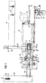
- the system shown serves to put balled shrub-like plants 10 in a bag 12 each made of shrinkable film and to close the bag in the area between plant shoots and root balls by locally shrinking.
- the bags 12 are, still interrelated, formed in a tubular film web, which is conveyed upright in a vertical longitudinal plane through the system and is slit open at the top.
- the individual bags 12 are delimited by vertical weld seams 14 which end below the upper bag edge regions 16 which are separated from one another by the slitting.
- Each bag 12 has a viewing surface 18 facing the viewer of FIG. 2, onto which an adhesive label 20 is to be glued.
- a binding label 22 is also to be added to each bag 12, which can be attached to the plant 10 when it is removed from the bag 12 at the planting location.
- Each binding label 22 has an eyelet 24 in which a binding wire 26 is fastened.
- the adhesive label 20 should be glued over the binding wire 26 and, for the sake of safety, also over the area of the eyelet 24.
- shrinking the bag 12 should eventually form a neck 28; below and also above the neck 28, the bag 12 should not be affected by the shrinkage or only relatively little.
- the system shown has an elongated machine frame 30, at the beginning of which, in FIGS. 1 and 2 on the right, a vertical decoiler 32 for the film web is mounted, in which the bags 12 are formed.
- the film web runs step by step over a tension roller 34 and over deflection rollers 36 and on one vertical support surface 38 along to a vertical tubular expansion body 40, which in plan view according to FIG. 1 has the shape of a ship's hull pointed at both ends.
- the expanding body 40 engages between the upper edge regions 16 of the bag and spreads them apart after each conveying step of the film web above a bag 12 to such an extent that the relevant bag 12 opens for receiving a balled plant 10.
- a take-up reel 44 Arranged above the rear end of the machine frame 30, which is on the left in FIGS. 1 and 2, is a take-up reel 44 for winding up the upper bag edge regions 16 torn off from the bags 12.
- a common motor 46 is provided for the movement of the film forming the bags 12 through the installation and for the rotation of the take-up reel 44.
- an adhesive label dispenser 48 and, above it, a binding label dispenser 50 are arranged.
- the adhesive label dispenser 48 as such is of a known type and is therefore not shown in detail.
- the binding label dispenser 50 has six label containers 52, each of which is attached to the end of an arm 56 which projects radially from a vertical shaft 54.
- the shaft 54 can be driven by a stepper motor 60 via a gear 58 such that one of the label containers 52 assumes a precisely defined removal position until it is completely empty.
- each label container 52 there is a vertical one on its narrow side facing away from the associated arm 56 Slit 62 formed, which opens into a bottom opening 64.
- each label container 52 contains a plurality of binding labels 22 lying flat on top of one another, the binding wires 26 of which project outwards through the slot 62.
- each label container 52 contains a weight 66 made of metal in its vertical slot 62, which loads the binding labels 22 and via the eyelets 24, which are also made of metal, is in electrically conductive connection with the associated, likewise metallic or metallized binding wires 26.
- the label containers 52 themselves are electrically non-conductive.
- Each of the weights 66 is connected via a flexible line 68 to a pole of an electrical power source, the second pole of which is connected to a contact 70 via a circuit (not shown).
- the binding wire 26 of the lowermost binding label 22 in the label container 52 which assumes the removal position, lies on the contact 70, whereby an electrical circuit is closed.
- This circuit is interrupted as soon as the last binding label 22 in the relevant label container 52 has been used up. This generates a signal which can rotate the shaft 54 until a label container 52 which has not yet been emptied has reached the removal position.
- the contact 70 is arranged at the end of a rail 71, which is made of electrically non-conductive material and is curved in an arc around the axis A such that when the shaft 54 is rotated, the binding wires 26 of this not yet emptied label container 52 run onto the rail 71 until they run finally reach contact 70. As a result, the circuit mentioned is closed again and the rotation about the axis A is consequently interrupted.
- the binding label dispenser 50 has a stamp 72, which in the example shown is designed as a suction cup and via a valve (not shown) is connected to a vacuum source.
- the stamp 72 is fastened to the end of an arm 74 which is displaceable along vertical guides 76 and horizontal guides 78 and is controlled by a link 80 in such a way that the stamp 72 approaches the label container 52 which is in the removal position from below during each working cycle, which pulls out the bottom binding label 22 through the bottom opening 64, swivels through 90 ° into an upright position and presses against the visible surface 18 of the relevant bag 12.
- the adhesive label dispenser 48 adheres an adhesive label 20 to the visible surface 18, which covers the binding wire 26 and the eyelet 24 of the binding label 22, so that it is securely attached to the bag 12.
- the arm 74 can be driven by a motor 82 which is fastened to a column 84 which also supports the shaft 54 and its bearing.
- the motor 82 is controlled by light barriers or other sensors which ensure that both label dispensers 48 and 50 act when a bag 12 has reached the working area of the stamp 72.
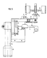
- a longitudinal conveyor 86 for example in the form of a conveyor belt, is provided to bring the plants 10, which are to be put into a bag 12 each, which rises like a ramp to a cross conveyor 88 and allows the plants 10 to fall at intervals therefrom.
- the cross conveyor 88 is in the example shown an open-topped channel in which a plant 10 can be displaced radially in the direction of the vertical axis B of a dip tube 92 by a slide 90 that can be moved pneumatically, for example.
- the dip tube 92 is arranged coaxially with the tubular expansion body 40 and can be moved up and down by a drive 94, for example a pneumatic piston-cylinder unit, between a take-over position in which the dip tube 92 only protrudes into the expansion body 40 from above and a lower end position, in which the immersion tube extends far into the bag 12 held open by the expansion body 40, if necessary almost to the bottom thereof.
- a drive 94 for example a pneumatic piston-cylinder unit
- the immersion tube 92 has a semi-tubular section 96, to which a likewise semi-tubular delivery channel 98 is assigned.
- This conveyor trough 98 is connected at its lower edge to the dip tube 92 by a joint 100 with a horizontal pivot axis C.
- the conveyor trough 98 opens obliquely into the dip tube 98, so that this can take over a plant 10 from the cross conveyor 88.
- the conveyor trough 98 is guided in such a way that it supplements the semi-tubular section 96 to a completely closed pipe section when the immersion pipe 92 is lowered. As a result, the plant 10 is forced to participate in the downward movement of the dip tube 92 and can only slide downward in it.
- the downward slide of the plant within the dip tube 92 is promoted by inertial forces when the downward movement of the dip tube ends more or less abruptly becomes. This may be sufficient to cause the plant 10 to slide downward in the dip tube 92 until the root ball settles on the bottom of the bag 12 into which the dip tube is immersed.
- a plunger-like stamp 102 is assigned to the dip tube 92, which normally assumes a rest position in the upper end region of the semi-tubular section 96 or even above it.
- the plunger 102 is connected to a piston-cylinder unit 104, which moves it downwards during or immediately after the lowering of the dip tube 92, so that the plunger 102 will certainly push the plant 10 down until its root ball is on the bottom of the bag 12.
- a holding device 106 Arranged below the expansion body 40 is a holding device 106, the task of which is to hold the bag 12 and the plant 10 introduced into it, preferably at their root ball, while the dip tube 92 is again moved upwards into its take-over position.
- the holding device 106 has a pair of jaws 108 which, for example, can be moved pneumatically towards and away from one another.
- the entire film strip on which the bags are formed is moved one step further.
- the bag which has just been filled comes into the area of action of a front nozzle 110 of each of the two nozzle groups 42, so that hot air escaping from them begins to cause the neck 28 to shrink.
- said bag 12 is exactly between two pairs of middle nozzles 112; the hot air flowing out of them continues the shrinkage at the neck 28.
- a further funding step is in Fig. 1 and 2 right edge region of the neck 28 between the rear nozzles 114 of the two nozzle groups 42, so that the shrinkage concentrated on the neck 28 is completed.
- the two nozzle groups 42 are supplied with hot air by a blower 116 each time a bag 12 has reached its area of influence. Careful thermal insulation of the nozzle groups 42 prevents excessive cooling in the intervals at which the fans 116 are stopped.
- the bag edge regions 16 are torn off the correspondingly perforated or otherwise prepared film web and wound up by the take-up reel 44. Simultaneously or immediately thereafter, the filled bags, which have been shrunk at their neck 28, are separated from one another by means of a separating device 118 and conveyed further by a longitudinal conveyor 120 and finally by a cross conveyor 122.
Landscapes
- Engineering & Computer Science (AREA)
- Mechanical Engineering (AREA)
- Labeling Devices (AREA)
- Packaging Of Special Articles (AREA)
- Basic Packing Technique (AREA)
- Breeding Of Plants And Reproduction By Means Of Culturing (AREA)
- Management, Administration, Business Operations System, And Electronic Commerce (AREA)
- Cultivation Of Plants (AREA)
- Package Closures (AREA)
- Portable Nailing Machines And Staplers (AREA)
- Supports For Plants (AREA)
- Cultivation Receptacles Or Flower-Pots, Or Pots For Seedlings (AREA)
Description
- Die Erfindung betrifft ein Verfahren und eine Vorrichtung zum Zuordnen von Bindeetiketten an Verpackungen von Strauchpflanzen.
- Pflanzen, u.a. Rosen- und andere Strauchpflanzen, werden immer häufiger über Supermärkte und andere Verkaufsstellen vertrieben, die nicht unbedingt über gärtnerisch geschultes Personal verfügen. Es ist deshalb wichtig, daß die zum Zwecke des Versandes und Verkaufs meist einzeln verpackten Pflanzen an gut sichtbarer Stelle der Verpackung mit einem Etikett versehen sind, das alle für den Käufer erforderlichen Angaben über Eigenschaften und Behandlung der betreffenden Pflanze in schriftlicher und/oder bildlicher Form enthält. Unabhängig davon kann es wünschenswert sein, der Pflanze ein Bindeetikett beizugeben, das auch nach dem Einpflanzen mit ihr verbunden bleibt. Solche Bindeetiketten können neben dem Pflanzennamen beispielsweise Angaben enthalten, die für die Durchführung von Lizenzverträgen von Bedeutung sind.
- Grundsätzlich ist es möglich, Bindeetiketten beim Verpacken von Pflanzen in die Verpackungen einzulegen. Andererseits könnte man Bindeetiketten schon bei oder vor dem Verpacken an Pflanzentriebe anbinden, die dann aus der Verpackung herausragen. In beiden Fällen ist es aber mühsam, bei einer Endkontrolle der verpackten Pflanzen festzustellen, ob jeder Pflanze ein und nur ein Bindeetikett beigegeben worden ist.
- Der Erfindung liegt deshalb die Aufgabe zugrunde, Pflanzenverpackungen in eindeutiger und arbeitssparender Weise Bindeetiketten zuzuordnen.
- Die Aufgabe ist, soweit sie das Verfahren zum Anbringen von Etiketten betrifft, erfindungsgemäß dadurch gelöst, daß ein Bindeetikett, an dem ein Bindedraht zum späteren Anbringen an einer Pflanze befestigt ist, mittels eines den Bindedraht abdeckenden Klebeetiketts an einer Pflanzenverpackung befestigt wird, aus der die Pflanze am Pflanzort herausgenommen wird.
- Das Befestigen des Bindeetiketts mittels des Klebeetiketts kann im einfachsten Fall manuell geschehen, indem eine Person mit einer Hand ein Bindeetikett an die Pflanzenverpackung anlegt und mit der anderen Hand das Klebeetikett über den Bindedraht klebt. Die Haftung des Klebeetiketts an der Pflanzenverpackung wird durch den dazwischenliegenden Bindedraht nicht beeinträchtigt und ist bei Klebeetiketten üblicher Größe selbst dann noch bei weitem ausreichend, wenn das Klebeetikett auch auf einen Teil des Bindeetiketts aufgeklebt wird, an dem der Bindedraht befestigt ist. Dieses Überkleben eines Teils des Bindeetiketts hat den Vorteil, daß das Bindeetikett ebenso wie das Klebeetikett flach an der Pflanzenverpackung anliegend gehalten wird, so daß beispielsweise mit optoelektronischen Einrichtungen bekannter Art in einer Verpackungsanlage zuverlässig nachgeprüft werden kann, ob jede Pflanzenverpackung neben dem Klebeetikett mit einem und nur mit einem Bindeetikett versehen worden ist.
- Soweit die beschriebene Aufgabe eine Vorrichtung betrifft, ist sie erfindungsgemäß gelöst durch
- mindestens einen Etikettenbehälter, in dem Bindeetiketten gestapelt und in einer Lage bereitgehalten werden, in der ihre Bindedrähte in gleicher Richtung angeordnet sind,
- einen Stempel zum Entnehmen eines Bindeetiketts aus dem Etikettenbehälter und Andrücken des Bindeetiketts an die zu etikettierende Pflanzenverpackung und
- einen Klebeetikettenspender zum Andrücken eines Klebeetiketts an den Bindedraht und die Pflanzenverpackung.
- Vorteilhafte Weiterbildungen ergeben sich aus den Unteransprüchen.
- Ein Ausführungsbeispiel der Erfindung wird im folgenden anhand schematischer Zeichnungen einer Anlage zum Verpacken und Etikettieren ballierter Strauchpflanzen, insbes. Rosenpflanzen, mit weiteren Einzelheiten erläutert.
- Es zeigen:
- Fig. 1 die Draufsicht der Anlage,
- Fig. 2 die Seitenansicht in Richtung des Pfeils II in Fig. 1,
- Fig. 3 die vergrößerte Teildraufsicht im Bereich des Pfeils III in Fig. 2,
- Fig. 4 die Ansicht in Richtung des Pfeils IV in Fig. 3,
- Fig. 5 die Ansicht in Richtung des Pfeils V in Fig. 3, und
- Fig. 6 den vergrößerten Teilschnitt III-III in Fig. 1.
- Die dargestellte Anlage dient dazu, ballierte strauchartige Pflanzen 10 in je einen Beutel 12 aus schrumpffähiger Folie zu stecken und den Beutel im Bereich zwischen Pflanzentrieben und Wurzelballen durch örtlich begrenztes Schrumpfen zu verschließen.
- Die Beutel 12 sind, noch miteinander zusammenhängend, in einer schlauchförmigen Folienbahn ausgebildet, die in einer senkrechten Längsebene aufrechtstehend waagerecht durch die Anlage hindurchgefördert wird und an ihrer Oberseite aufgeschlitzt ist. Die einzelnen Beutel 12 sind durch senkrechte Schweißnähte 14 begrenzt, die unterhalb der durch das Aufschlitzen voneinander getrennten oberen Beutelrandbereiche 16 enden. Jeder Beutel 12 hat eine dem Betrachter der Fig. 2 zugewandte Sichtfläche 18, auf die ein Klebeetikett 20 aufgeklebt werden soll.
- Jedem Beutel 12 soll ferner ein Bindeetikett 22 beigegeben werden, das an der Pflanze 10 befestigt werden kann, wenn diese am Pflanzort aus dem Beutel 12 herausgenommen wird. Jedes Bindeetikett 22 hat eine Öse 24, in der ein Bindedraht 26 befestigt ist. Zum Befestigen des Bindeetiketts 22 am Beutel 12 soll das Klebeetikett 20 über den Bindedraht 26 und sicherheitshalber auch über den Bereich der Öse 24 geklebt werden. Durch Schrumpfen soll der Beutel 12 schließlich einen Hals 28 bilden; unterhalb und auch oberhalb des Halses 28 soll der Beutel 12 aber vom Schrumpfen nicht oder nur verhältnismäßig wenig betroffen werden.
- Die dargestellte Anlage hat ein langgestrecktes Maschinengestell 30, an dessen Anfang, in Fig. 1 und 2 rechts, eine senkrechte Abwickelhaspel 32 für die Folienbahn gelagert ist, in der die Beutel 12 ausgebildet sind. Ausgehend von der Haspel 32 läuft die Folienbahn schrittweise über eine Spannrolle 34 sowie über Umlenkrollen 36 und an einer senkrechten Stützfläche 38 entlang zu einem senkrechten rohrförmigen Spreizkörper 40, der in Draufsicht gemäß Fig. 1 die Form eines an beiden Enden spitzen Schiffsrumpfes hat. Der Spreizkörper 40 greift zwischen die oberen Beutelrandbereiche 16 ein und spreizt sie nach jedem Förderschritt der Folienbahn oberhalb eines Beutels 12 soweit auseinander, daß der betreffende Beutel 12 sich zum Aufnehmen einer ballierten Pflanze 10 öffnet.
- Die Beutel 12, die noch zusammenhängen, nun aber mit je einer Pflanze 10 gefüllt sind, laufen anschließend zum Schrumpfen ihres Halses 28 zwischen zwei Düsengruppen 42 hindurch. Oberhalb des hinteren, in Fig. 1 und 2 linken Endes des Maschinengestells 30 ist eine Aufwickelhaspel 44 zum Aufwickeln der von den Beuteln 12 abgerissenen oberen Beutelrandbereiche 16 angeordnet. Für die Bewegung der die Beutel 12 bildenden Folie durch die Anlage hindurch und zum Drehen der Aufwickelhaspel 44 ist ein gemeinsamer Motor 46 vorgesehen.
- Am Anfang der Anlage, in Fig. 1 und 2 rechts, sind ein Klebeetikettenspender 48 und, darüber, ein Bindeetikettenspender 50 angeordnet. Der Klebeetikettenspender 48 ist als solcher von bekannter Bauart und deshalb nicht näher dargestellt. Der Bindeetikettenspender 50 hat im dargestellten Beispiel sechs Etikettenbehälter 52, die am Ende je eines von einer senkrechte Welle 54 radial wegragenden Arms 56 befestigt sind. Die Welle 54 ist über ein Getriebe 58 von einem Schrittmotor 60 derart antreibbar ist, daß jeweils einer der Etikettenbehälter 52 eine genau festgelegte Entnahmestellung solange einnimmt, bis er vollständig geleert ist.
- In jedem Etikettenbehälter 52 ist, an dessen vom zugehörigen Arm 56 abgewandter Schmalseite, ein senkrechter Schlitz 62 ausgebildet, der in eine Bodenöffnung 64 mündet. In gefülltem Zustand enthält jeder Etikettenbehälter 52 eine Vielzahl flach aufeinanderliegender Bindeetiketten 22, deren Bindedrähte 26 durch den Schlitz 62 nach außen ragen. Ferner enthält jeder Etikettenbehälter 52 ein in seinem senkrechten Schlitz 62 geführtes Gewicht 66 aus Metall, das die Bindeetiketten 22 belastet und über deren Ösen 24, die ebenfalls aus Metall bestehen, mit den zugehörigen, gleichfalls metallischen oder metallisierten Bindedrähten 26 in elektrisch leitender Verbindung steht. Die Etikettenbehälter 52 selbst sind elektrisch nichtleitend.
- Jedes der Gewichte 66 ist über eine flexible Leitung 68 mit einem Pol einer elektrischen Stromquelle verbunden, deren zweiter Pol über eine nicht dargestellte Schaltung an einen Kontakt 70 angeschlossen ist. Der Bindedraht 26 des untersten Bindeetiketts 22 in dem Etikettenbehälter 52, der die Entnahmestellung einnimmt, liegt auf dem Kontakt 70 auf, wodurch ein elektrischer Stromkreis geschlossen wird.
- Dieser Stromkreis wird unterbrochen, sobald das letzte Bindeetikett 22 in dem betreffenden Etikettenbehälter 52 verbraucht ist. Dadurch wird ein Signal erzeugt, das die Welle 54 sich solange drehen läßt, bis ein noch nicht geleerter Etikettenbehälter 52 die Entnahmestellung erreicht hat. Der Kontakt 70 ist am Ende einer Schiene 71 angeordnet, die aus elektrisch nichtleitendem Werkstoff besteht und bogenförmig derart um die Achse A gekrümmt ist, daß beim Drehen der Welle 54 die Bindedrähte 26 dieses noch nicht geleerten Etikettenbehälters 52 auf die Schiene 71 auflaufen, bis sie schließlich den Kontakt 70 erreichen. Dadurch wird der genannte Stromkreis wieder geschlossen und infolgedessen die Drehung um die Achse A unterbrochen.
- Zum Entnehmen jeweils eines Bindeetiketts 22 aus dem in Entnahmestellung stehenden Etikettenbehälter 52, und zum Andrücken dieses Bindeetiketts 22 an die Sichtfläche 18 jeweils eines Beutels 12 weist der Bindeetikettenspender 50 einen Stempel 72 auf, der im dargestellten Beispiel als Saugnapf ausgebildet und über ein nicht dargestelltes Ventil an eine Vakuumquelle angeschlossen ist. Der Stempel 72 ist am Ende eines Arms 74 befestigt, der längs senkrechter Führungen 76 und waagerechter Führungen 78 verschiebbar und durch eine Kulisse 80 derart gesteuert ist, daß der Stempel 72 sich bei jedem Arbeitszyklus von unten her dem in Entnahmestellung stehenden Etikettenbehälter 52 nähert, das unterste Bindeetikett 22 durch die Bodenöffnung 64 nach unten herauszieht, um 90° in eine Hochkantstellung schwenkt und an die Sichtfläche 18 des betreffenden Beutels 12 andrückt. Unmittelbar darauf klebt der Klebeetikettenspender 48 an die Sichtfläche 18 ein Klebeetikett 20 an, das den Bindedraht 26 und die Öse 24 des Bindeetiketts 22 überdeckt, so daß dieses am Beutel 12 sicher befestigt wird.
- Der Arm 74 ist von einem Motor 82 antreibbar, der an einer auch die Welle 54 und deren Lagerung tragenden Säule 84 befestigt ist. Der Motor 82 ist von Lichtschranken oder anderen Sensoren gesteuert, die sicherstellen, daß beide Etikettenspender 48 und 50 jeweils dann tätig werden, wenn ein Beutel 12 den Arbeitsbereich des Stempels 72 erreicht hat.
- Zum Heranschaffen der Pflanzen 10, die in je einen Beutel 12 gesteckt werden sollen, ist ein Längsförderer 86, beispielsweise in Gestalt eines Förderbandes vorgesehen, der rampenartig zu einem Querförderer 88 hin ansteigt und auf diesen die Pflanzen 10 in Abständen hintereinander fallen läßt. Der Querförderer 88 ist im dargestellten Beispiel ein oben offener Kanal, in dem jeweils eine Pflanze 10 von einem beispielsweise pneumatisch hin- und herbewegbaren Schieber 90 radial in Richtung auf die senkrechte Achse B eines Tauchrohrs 92 verschiebbar ist.
- Das Tauchrohr 92 ist gleichachsig mit dem rohrförmigen Spreizkörper 40 angeordnet und von einem Antrieb 94, beispielsweise einer pneumatischen Kolbenzylindereinheit, auf- und abbewegbar zwischen einer Übernahmestellung, in der das Tauchrohr 92 von oben her nur in den Spreizkörper 40 hineinragt, und einer unteren Endstellung, in der das Tauchrohr weit in den vom Spreizkörper 40 offengehaltenen Beutel 12 hineinragt, gewünschtenfalls nahezu bis zu dessen Boden.
- Das Tauchrohr 92 hat in seinem oberen Bereich einen halbrohrförmigen Abschnitt 96, dem eine ebenfalls halbrohrförmige Förderrinne 98 zugeordnet ist. Diese Förderrinne 98 ist an ihrem unteren Rand durch ein Gelenk 100 mit waagerechter Schwenkachse C mit dem Tauchrohr 92 verbunden. In der Übernahmestellung des Tauchrohrs 98, die in Fig. 6 abgebildet ist, mündet die Förderrinne 98 schräg in das Tauchrohr 98, so daß dieses eine Pflanze 10 vom Querförderer 88 übernehmen kann. Die Förderrinne 98 ist derart geführt, daß sie den halbrohrförmigen Abschnitt 96 zu einem vollständig geschlossenen Rohrabschnitt ergänzt, wenn das Tauchrohr 92 abgesenkt wird. Die Pflanze 10 ist infolgedessen gezwungen, an der Abwärtsbewegung des Tauchrohrs 92 teilzunehmen und kann in ihm nur mehr nach unten rutschen.
- Das Abwärtsrutschen der Pflanze innerhalb des in der beschriebenen Weise seitlich geschlossenen Tauchrohrs 92 wird durch Trägheitskräfte gefördert, wenn die Abwärtsbewegung des Tauchrohrs mehr oder weniger abrupt beendet wird. Dies kann genügen, um die Pflanze 10 im Tauchrohr 92 soweit nach unten rutschen zu lassen, daß der Wurzelballen sich auf den Boden des Beutels 12 aufsetzt, in den das Tauchrohr eingetaucht ist. Sicherheitshalber ist jedoch dem Tauchrohr 92 ein kolbenartiger Stempel 102 zugeordnet, der normalerweise eine Ruhestellung im oberen Endbereich des halbrohrförmigen Abschnittes 96 oder sogar oberhalb davon einnimmt. Der Stempel 102 ist mit einer Kolbenzylindereinheit 104 verbunden, die ihn während oder unmittelbar nach dem Absenken des Tauchrohrs 92 abwärtsbewegt, so daß der Stempel 102 die Pflanze 10 mit Sicherheit soweit nach unten schiebt, bis ihr Wurzelballen auf dem Boden des Beutels 12 steht.
- Unterhalb des Spreizkörpers 40 ist eine Haltevorrichtung 106 angeordnet, deren Aufgabe es ist, den Beutel 12 und die in ihn eingebrachte Pflanze 10 festzuhalten, vorzugsweise an ihrem Wurzelballen, während das Tauchrohr 92 wieder nach oben in seine Übernahmestellung bewegt wird. Im dargestellten Beispiel hat die Haltevorrichtung 106 ein Paar Backen 108, die beispielsweise pneumatisch zueinander hin und voneinander weg bewegbar sind.
- Sobald das Tauchrohr 92 aus dem soeben gefüllten Beutel 12 zurückgezogen worden ist, wird das gesamte Folienband, an dem die Beutel ausgebildet sind, um einen Schritt weiterbewegt. Dadurch gelangt der soeben gefüllte Beutel mit seinem in Fig. 1 und 2 linken Rand in den Einwirkungsbereich je einer vorderen Düse 110 der beiden Düsengruppen 42, so daß aus diesen auströmende Heißluft beginnt, den Hals 28 zum Schrumpfen zu bringen. Nach dem nächsten Förderschritt steht der genannte Beutel 12 genau zwischen zwei Paar mittleren Düsen 112; die aus diesen ausströmende Heißluft setzt die Schrumpfung am Hals 28 verstärkt fort. Nach einem weiteren Förderschritt steht der in Fig. 1 und 2 rechte Randbereich des Halses 28 zwischen hinteren Düsen 114 der beiden Düsengruppen 42, so daß die auf den Hals 28 konzentrierte Schrumpfung vollendet wird.
- Die beiden Düsengruppen 42 werden von je einem Gebläse 116 immer dann mit Heißluft versorgt, wenn ein Beutel 12 in ihren Einwirkungsbereich gelangt ist. Eine sorgfältige Wärmeisolation der Düsengruppen 42 verhindert eine übermäßige Abkühlung in den Intervallen, in denen die Gebläse 116 stillstehen.
- Förderstromabwärts von den Düsengruppen 42 werden die Beutelrandbereiche 16 von der entsprechend perforierten oder anderweitig vorbereiteten Folienbahn abgerissen und von der Aufwickelhaspel 44 aufgewickelt. Gleichzeitig oder unmittelbar danach werden die gefüllten und an ihrem Hals 28 geschrumpften Beutel mittels einer Trennvorrichtung 118 voneinander getrennt und von einem Längsförderer 120 sowie schließlich von einem Querförderer 122 weitergefördert.
Claims (10)
Applications Claiming Priority (2)
| Application Number | Priority Date | Filing Date | Title |
|---|---|---|---|
| DE3904044 | 1989-02-10 | ||
| DE3904044A DE3904044A1 (de) | 1989-02-10 | 1989-02-10 | Verfahren und vorrichtung zum anbringen von etiketten an pflanzenpackungen |
Publications (2)
| Publication Number | Publication Date |
|---|---|
| EP0382248A1 EP0382248A1 (de) | 1990-08-16 |
| EP0382248B1 true EP0382248B1 (de) | 1992-04-22 |
Family
ID=6373844
Family Applications (1)
| Application Number | Title | Priority Date | Filing Date |
|---|---|---|---|
| EP90102590A Expired - Lifetime EP0382248B1 (de) | 1989-02-10 | 1990-02-09 | Verfahren und Vorrichtung zum Zuordnen von Bindeetiketten zu Strauchpflanzen |
Country Status (12)
| Country | Link |
|---|---|
| EP (1) | EP0382248B1 (de) |
| JP (1) | JPH03504484A (de) |
| AT (1) | ATE75197T1 (de) |
| CA (1) | CA2024018A1 (de) |
| DD (1) | DD292190A5 (de) |
| DE (2) | DE3904044A1 (de) |
| DK (1) | DK0382248T3 (de) |
| ES (1) | ES2030599T3 (de) |
| GR (1) | GR3004831T3 (de) |
| HU (1) | HU206295B (de) |
| RU (1) | RU1838192C (de) |
| WO (1) | WO1990009319A1 (de) |
Family Cites Families (11)
| Publication number | Priority date | Publication date | Assignee | Title |
|---|---|---|---|---|
| US2952851A (en) * | 1959-06-03 | 1960-09-20 | Epstein Melvin | Self-loading fastener means |
| US3440116A (en) * | 1964-05-08 | 1969-04-22 | Smithkline Corp | Method and device for securing an article to a container |
| US3549459A (en) * | 1968-05-08 | 1970-12-22 | Smithkline Corp | Device for securing an article to a container |
| US3910811A (en) * | 1974-07-18 | 1975-10-07 | Kwik Lok | Method and machine for removeably securing stiff plastic closures flat against series of moving packages |
| DE2719216A1 (de) * | 1977-04-29 | 1978-11-09 | Bausch & Stroebel Maschf | Zufuehrungsvorrichtung fuer etiketten zu einer abnahmeeinrichtung |
| DE3002250C2 (de) * | 1980-01-23 | 1984-03-29 | Jagenberg-Werke AG, 4000 Düsseldorf | Vorrichtung zum Bereitstellen von Etiketten an einer Etikettiermaschine |
| US4351679A (en) * | 1980-08-08 | 1982-09-28 | Culbro Corporation | Label-leaflet applying apparatus |
| US4605459A (en) * | 1984-02-03 | 1986-08-12 | New Jersey Machine Inc. | Literature applying machine and method |
| DE3419848A1 (de) * | 1984-05-28 | 1985-11-28 | Croon & Lucke Maschinenfabrik Gmbh + Co Kg, 7947 Mengen | Magazin fuer garnknaeuel-etiketten |
| JPS6169534A (ja) * | 1984-09-11 | 1986-04-10 | 株式会社 サト− | ラベル自動貼付機 |
| DE3721561C2 (de) * | 1987-06-30 | 1996-08-29 | Stocker Ludwig Hofpfisterei | Vorrichtung zum Aufbringen eines Etiketts auf einen Teigkörper, insbesondere einen Brotteigkörper |
-
1989
- 1989-02-10 DE DE3904044A patent/DE3904044A1/de active Granted
-
1990
- 1990-02-09 WO PCT/EP1990/000215 patent/WO1990009319A1/de not_active Ceased
- 1990-02-09 HU HU901719A patent/HU206295B/hu not_active IP Right Cessation
- 1990-02-09 DE DE9090102590T patent/DE59000094D1/de not_active Expired - Fee Related
- 1990-02-09 AT AT90102590T patent/ATE75197T1/de not_active IP Right Cessation
- 1990-02-09 JP JP2502960A patent/JPH03504484A/ja active Pending
- 1990-02-09 EP EP90102590A patent/EP0382248B1/de not_active Expired - Lifetime
- 1990-02-09 CA CA002024018A patent/CA2024018A1/en not_active Abandoned
- 1990-02-09 ES ES199090102590T patent/ES2030599T3/es not_active Expired - Lifetime
- 1990-02-09 DD DD90337737A patent/DD292190A5/de not_active IP Right Cessation
- 1990-02-09 DK DK90102590.8T patent/DK0382248T3/da active
- 1990-10-09 RU SU904831349A patent/RU1838192C/ru active
-
1992
- 1992-06-04 GR GR920401175T patent/GR3004831T3/el unknown
Also Published As
| Publication number | Publication date |
|---|---|
| CA2024018A1 (en) | 1990-08-11 |
| JPH03504484A (ja) | 1991-10-03 |
| DE59000094D1 (de) | 1992-05-27 |
| DK0382248T3 (da) | 1992-08-10 |
| ES2030599T3 (es) | 1992-11-01 |
| EP0382248A1 (de) | 1990-08-16 |
| DD292190A5 (de) | 1991-07-25 |
| ATE75197T1 (de) | 1992-05-15 |
| HU901719D0 (en) | 1991-04-29 |
| GR3004831T3 (de) | 1993-04-28 |
| DE3904044A1 (de) | 1990-08-16 |
| DE3904044C2 (de) | 1990-12-20 |
| WO1990009319A1 (de) | 1990-08-23 |
| HU206295B (en) | 1992-10-28 |
| RU1838192C (ru) | 1993-08-30 |
| HUT55690A (en) | 1991-06-28 |
Similar Documents
| Publication | Publication Date | Title |
|---|---|---|
| DE69908559T2 (de) | Verfahren und vorrichtung zum umhüllen einer ladung mit dehnfolie | |
| EP0706946B1 (de) | Verfahren und Vorrichtung zum Handhaben von Zuschnitt-Stapeln mit Banderolen | |
| DE102009004134A1 (de) | Verfahren und Vorrichtung zum Herstellen von Gebindepackungen sowie Gebindepackung | |
| DE3143063A1 (de) | Vorrichtung zum einhuellen von rollen | |
| EP0149076B1 (de) | Verfahren und Vorrichtung zum Anbringen von Trinkhalmen an Getränkebehältern, insbesondere an Getränkebeuteln | |
| DE1561966A1 (de) | Verfahren und Vorrichtung zum Verpacken von Waren | |
| DE3148186A1 (de) | Verfahren und vorrichtung zum oeffnen und beladen eines flexiblen behaelters | |
| DE1811213A1 (de) | Verfahren und Vorrichtung zum OEffnen,Fuellen und Schliessen von Beuteln od.dgl. | |
| DE102017010642A1 (de) | Verfahren und Vorrichtung zum Aufbringen von Etiketten auf Zigarettenpackungen | |
| DE2809360B2 (de) | Verfahren und Vorrichtung zum Wickeln und Kassettieren eines Filmbandes | |
| DE10109875B4 (de) | Trinkhalmanbringvorrichtung und -verfahren | |
| DE2221039A1 (de) | Verfahren und Vorrichtung zum automatischen Ansetzen von Beuteln an eine Abfuellvorrichtung | |
| DE2322377A1 (de) | Verfahren zum verpacken von gegenstaenden und maschine zur durchfuehrung des verfahrens | |
| EP0382248B1 (de) | Verfahren und Vorrichtung zum Zuordnen von Bindeetiketten zu Strauchpflanzen | |
| EP0864500B1 (de) | Verfahren und Vorrichtung zum Öffnen der äusseren Umhüllung einer Bobine aus Verpackungsmaterial | |
| DD292193A5 (de) | Verfahren und vorrichtung zum zuordnen von bindeetiketten zu strauchpflanzen | |
| DE2503562A1 (de) | Verfahren und vorrichtung zum anbringen von gusstuellen an behaeltern | |
| DE4417648A1 (de) | Verfahren und Vorrichtung zum Etikettieren von Verpackungsbehältern | |
| EP3323745B1 (de) | Behälterbehandlungsmaschine und verfahren zur behandlung von behältern | |
| EP0382252B1 (de) | Vorrichtung zum Füllen von Beuteln mit sperrigem Füllgut | |
| EP1274627B1 (de) | Vorrichtung und verfahren zum anbringen eines sicherungselementes auf einem etikett | |
| DE3102872A1 (de) | Verfahren und vorrichtung zum umhuellen von schokoladetafeln oder -riegeln mit einer verpackungsfolie, insbes. mit einer metallfolie | |
| DE102014113393A1 (de) | Verfahren sowie Vorrichtung zum Herstellen von Verpackungsgebinden | |
| DE3904043C2 (de) | ||
| EP0954957A1 (de) | Landwirtschaftliche Aufsammel-, Transport- und Absetzeinheit |
Legal Events
| Date | Code | Title | Description |
|---|---|---|---|
| PUAI | Public reference made under article 153(3) epc to a published international application that has entered the european phase |
Free format text: ORIGINAL CODE: 0009012 |
|
| AK | Designated contracting states |
Kind code of ref document: A1 Designated state(s): AT BE CH DE DK ES FR GB GR IT LI LU NL SE |
|
| 17P | Request for examination filed |
Effective date: 19900821 |
|
| 17Q | First examination report despatched |
Effective date: 19910807 |
|
| GRAA | (expected) grant |
Free format text: ORIGINAL CODE: 0009210 |
|
| ITF | It: translation for a ep patent filed | ||
| AK | Designated contracting states |
Kind code of ref document: B1 Designated state(s): AT BE CH DE DK ES FR GB GR IT LI LU NL SE |
|
| PG25 | Lapsed in a contracting state [announced via postgrant information from national office to epo] |
Ref country code: GR Free format text: LAPSE BECAUSE OF FAILURE TO SUBMIT A TRANSLATION OF THE DESCRIPTION OR TO PAY THE FEE WITHIN THE PRESCRIBED TIME-LIMIT Effective date: 19920422 |
|
| REF | Corresponds to: |
Ref document number: 75197 Country of ref document: AT Date of ref document: 19920515 Kind code of ref document: T |
|
| REF | Corresponds to: |
Ref document number: 59000094 Country of ref document: DE Date of ref document: 19920527 |
|
| ET | Fr: translation filed | ||
| GBT | Gb: translation of ep patent filed (gb section 77(6)(a)/1977) | ||
| REG | Reference to a national code |
Ref country code: DK Ref legal event code: T3 |
|
| REG | Reference to a national code |
Ref country code: ES Ref legal event code: FG2A Ref document number: 2030599 Country of ref document: ES Kind code of ref document: T3 |
|
| REG | Reference to a national code |
Ref country code: GR Ref legal event code: FG4A Free format text: 3004831 |
|
| PG25 | Lapsed in a contracting state [announced via postgrant information from national office to epo] |
Ref country code: DK Effective date: 19930209 Ref country code: AT Effective date: 19930209 |
|
| REG | Reference to a national code |
Ref country code: DK Ref legal event code: EBP |
|
| PG25 | Lapsed in a contracting state [announced via postgrant information from national office to epo] |
Ref country code: SE Effective date: 19930210 |
|
| PGFP | Annual fee paid to national office [announced via postgrant information from national office to epo] |
Ref country code: ES Payment date: 19930224 Year of fee payment: 4 |
|
| PLBE | No opposition filed within time limit |
Free format text: ORIGINAL CODE: 0009261 |
|
| STAA | Information on the status of an ep patent application or granted ep patent |
Free format text: STATUS: NO OPPOSITION FILED WITHIN TIME LIMIT |
|
| PG25 | Lapsed in a contracting state [announced via postgrant information from national office to epo] |
Ref country code: LU Free format text: LAPSE BECAUSE OF NON-PAYMENT OF DUE FEES Effective date: 19930228 Ref country code: LI Effective date: 19930228 Ref country code: CH Effective date: 19930228 Ref country code: BE Effective date: 19930228 |
|
| 26N | No opposition filed | ||
| BERE | Be: lapsed |
Owner name: W. KORDES'SOHNE ROSENSCHULEN G.M.B.H. & CO. K.G. Effective date: 19930228 |
|
| PG25 | Lapsed in a contracting state [announced via postgrant information from national office to epo] |
Ref country code: NL Effective date: 19930901 |
|
| NLV4 | Nl: lapsed or anulled due to non-payment of the annual fee | ||
| PG25 | Lapsed in a contracting state [announced via postgrant information from national office to epo] |
Ref country code: FR Effective date: 19931029 |
|
| REG | Reference to a national code |
Ref country code: CH Ref legal event code: PL |
|
| PGFP | Annual fee paid to national office [announced via postgrant information from national office to epo] |
Ref country code: GB Payment date: 19931222 Year of fee payment: 5 |
|
| REG | Reference to a national code |
Ref country code: FR Ref legal event code: ST |
|
| PG25 | Lapsed in a contracting state [announced via postgrant information from national office to epo] |
Ref country code: ES Free format text: LAPSE BECAUSE OF NON-PAYMENT OF DUE FEES Effective date: 19940210 |
|
| PGFP | Annual fee paid to national office [announced via postgrant information from national office to epo] |
Ref country code: DE Payment date: 19940222 Year of fee payment: 5 |
|
| REG | Reference to a national code |
Ref country code: GR Ref legal event code: MM2A Free format text: 3004831 |
|
| EUG | Se: european patent has lapsed |
Ref document number: 90102590.8 Effective date: 19930912 |
|
| PG25 | Lapsed in a contracting state [announced via postgrant information from national office to epo] |
Ref country code: GB Effective date: 19950209 |
|
| GBPC | Gb: european patent ceased through non-payment of renewal fee |
Effective date: 19950209 |
|
| PG25 | Lapsed in a contracting state [announced via postgrant information from national office to epo] |
Ref country code: DE Effective date: 19951101 |
|
| REG | Reference to a national code |
Ref country code: ES Ref legal event code: FD2A Effective date: 19990301 |
|
| PG25 | Lapsed in a contracting state [announced via postgrant information from national office to epo] |
Ref country code: IT Free format text: LAPSE BECAUSE OF NON-PAYMENT OF DUE FEES;WARNING: LAPSES OF ITALIAN PATENTS WITH EFFECTIVE DATE BEFORE 2007 MAY HAVE OCCURRED AT ANY TIME BEFORE 2007. THE CORRECT EFFECTIVE DATE MAY BE DIFFERENT FROM THE ONE RECORDED. Effective date: 20050209 |