EP0382132B1 - Transmission continue hydromécanique de vitesse avec accouplements dentés - Google Patents
Transmission continue hydromécanique de vitesse avec accouplements dentés Download PDFInfo
- Publication number
- EP0382132B1 EP0382132B1 EP90102183A EP90102183A EP0382132B1 EP 0382132 B1 EP0382132 B1 EP 0382132B1 EP 90102183 A EP90102183 A EP 90102183A EP 90102183 A EP90102183 A EP 90102183A EP 0382132 B1 EP0382132 B1 EP 0382132B1
- Authority
- EP
- European Patent Office
- Prior art keywords
- gear
- old
- hydrostatic drive
- flank
- toothed
- Prior art date
- Legal status (The legal status is an assumption and is not a legal conclusion. Google has not performed a legal analysis and makes no representation as to the accuracy of the status listed.)
- Expired - Lifetime
Links
- 230000005540 biological transmission Effects 0.000 title claims description 16
- 230000008878 coupling Effects 0.000 claims description 22
- 238000010168 coupling process Methods 0.000 claims description 22
- 238000005859 coupling reaction Methods 0.000 claims description 22
- 230000001360 synchronised effect Effects 0.000 claims description 18
- 238000006073 displacement reaction Methods 0.000 claims description 17
- 230000002706 hydrostatic effect Effects 0.000 claims description 16
- 230000000694 effects Effects 0.000 claims 1
- 230000007246 mechanism Effects 0.000 claims 1
- 238000000034 method Methods 0.000 description 3
- 230000035939 shock Effects 0.000 description 3
- 238000012937 correction Methods 0.000 description 2
- 238000000926 separation method Methods 0.000 description 2
- 230000001133 acceleration Effects 0.000 description 1
- 238000002485 combustion reaction Methods 0.000 description 1
- 238000013270 controlled release Methods 0.000 description 1
- 230000001419 dependent effect Effects 0.000 description 1
- 238000010586 diagram Methods 0.000 description 1
- 239000000446 fuel Substances 0.000 description 1
- XDDAORKBJWWYJS-UHFFFAOYSA-N glyphosate Chemical compound OC(=O)CNCP(O)(O)=O XDDAORKBJWWYJS-UHFFFAOYSA-N 0.000 description 1
- 238000004519 manufacturing process Methods 0.000 description 1
- 230000007935 neutral effect Effects 0.000 description 1
Images


Classifications
-
- F—MECHANICAL ENGINEERING; LIGHTING; HEATING; WEAPONS; BLASTING
- F16—ENGINEERING ELEMENTS AND UNITS; GENERAL MEASURES FOR PRODUCING AND MAINTAINING EFFECTIVE FUNCTIONING OF MACHINES OR INSTALLATIONS; THERMAL INSULATION IN GENERAL
- F16H—GEARING
- F16H47/00—Combinations of mechanical gearing with fluid clutches or fluid gearing
- F16H47/02—Combinations of mechanical gearing with fluid clutches or fluid gearing the fluid gearing being of the volumetric type
- F16H47/04—Combinations of mechanical gearing with fluid clutches or fluid gearing the fluid gearing being of the volumetric type the mechanical gearing being of the type with members having orbital motion
-
- F—MECHANICAL ENGINEERING; LIGHTING; HEATING; WEAPONS; BLASTING
- F16—ENGINEERING ELEMENTS AND UNITS; GENERAL MEASURES FOR PRODUCING AND MAINTAINING EFFECTIVE FUNCTIONING OF MACHINES OR INSTALLATIONS; THERMAL INSULATION IN GENERAL
- F16D—COUPLINGS FOR TRANSMITTING ROTATION; CLUTCHES; BRAKES
- F16D23/00—Details of mechanically-actuated clutches not specific for one distinct type
- F16D23/02—Arrangements for synchronisation, also for power-operated clutches
- F16D23/04—Arrangements for synchronisation, also for power-operated clutches with an additional friction clutch
- F16D23/06—Arrangements for synchronisation, also for power-operated clutches with an additional friction clutch and a blocking mechanism preventing the engagement of the main clutch prior to synchronisation
- F16D2023/0656—Details of the tooth structure; Arrangements of teeth
- F16D2023/0662—Details relating to special geometry of arrangements of teeth
-
- F—MECHANICAL ENGINEERING; LIGHTING; HEATING; WEAPONS; BLASTING
- F16—ENGINEERING ELEMENTS AND UNITS; GENERAL MEASURES FOR PRODUCING AND MAINTAINING EFFECTIVE FUNCTIONING OF MACHINES OR INSTALLATIONS; THERMAL INSULATION IN GENERAL
- F16D—COUPLINGS FOR TRANSMITTING ROTATION; CLUTCHES; BRAKES
- F16D23/00—Details of mechanically-actuated clutches not specific for one distinct type
- F16D23/02—Arrangements for synchronisation, also for power-operated clutches
- F16D23/04—Arrangements for synchronisation, also for power-operated clutches with an additional friction clutch
- F16D23/06—Arrangements for synchronisation, also for power-operated clutches with an additional friction clutch and a blocking mechanism preventing the engagement of the main clutch prior to synchronisation
- F16D2023/0656—Details of the tooth structure; Arrangements of teeth
- F16D2023/0668—Details relating to tooth end or tip geometry
-
- F—MECHANICAL ENGINEERING; LIGHTING; HEATING; WEAPONS; BLASTING
- F16—ENGINEERING ELEMENTS AND UNITS; GENERAL MEASURES FOR PRODUCING AND MAINTAINING EFFECTIVE FUNCTIONING OF MACHINES OR INSTALLATIONS; THERMAL INSULATION IN GENERAL
- F16D—COUPLINGS FOR TRANSMITTING ROTATION; CLUTCHES; BRAKES
- F16D23/00—Details of mechanically-actuated clutches not specific for one distinct type
- F16D23/02—Arrangements for synchronisation, also for power-operated clutches
- F16D23/04—Arrangements for synchronisation, also for power-operated clutches with an additional friction clutch
- F16D23/06—Arrangements for synchronisation, also for power-operated clutches with an additional friction clutch and a blocking mechanism preventing the engagement of the main clutch prior to synchronisation
- F16D23/0612—Arrangements for synchronisation, also for power-operated clutches with an additional friction clutch and a blocking mechanism preventing the engagement of the main clutch prior to synchronisation the blocking mechanism comprising a radial pin in an axial slot with at least one branch
-
- F—MECHANICAL ENGINEERING; LIGHTING; HEATING; WEAPONS; BLASTING
- F16—ENGINEERING ELEMENTS AND UNITS; GENERAL MEASURES FOR PRODUCING AND MAINTAINING EFFECTIVE FUNCTIONING OF MACHINES OR INSTALLATIONS; THERMAL INSULATION IN GENERAL
- F16H—GEARING
- F16H37/00—Combinations of mechanical gearings, not provided for in groups F16H1/00 - F16H35/00
- F16H37/02—Combinations of mechanical gearings, not provided for in groups F16H1/00 - F16H35/00 comprising essentially only toothed or friction gearings
- F16H37/06—Combinations of mechanical gearings, not provided for in groups F16H1/00 - F16H35/00 comprising essentially only toothed or friction gearings with a plurality of driving or driven shafts; with arrangements for dividing torque between two or more intermediate shafts
- F16H37/08—Combinations of mechanical gearings, not provided for in groups F16H1/00 - F16H35/00 comprising essentially only toothed or friction gearings with a plurality of driving or driven shafts; with arrangements for dividing torque between two or more intermediate shafts with differential gearing
- F16H37/0833—Combinations of mechanical gearings, not provided for in groups F16H1/00 - F16H35/00 comprising essentially only toothed or friction gearings with a plurality of driving or driven shafts; with arrangements for dividing torque between two or more intermediate shafts with differential gearing with arrangements for dividing torque between two or more intermediate shafts, i.e. with two or more internal power paths
- F16H37/084—Combinations of mechanical gearings, not provided for in groups F16H1/00 - F16H35/00 comprising essentially only toothed or friction gearings with a plurality of driving or driven shafts; with arrangements for dividing torque between two or more intermediate shafts with differential gearing with arrangements for dividing torque between two or more intermediate shafts, i.e. with two or more internal power paths at least one power path being a continuously variable transmission, i.e. CVT
- F16H2037/088—Power split variators with summing differentials, with the input of the CVT connected or connectable to the input shaft
- F16H2037/0886—Power split variators with summing differentials, with the input of the CVT connected or connectable to the input shaft with switching means, e.g. to change ranges
-
- F—MECHANICAL ENGINEERING; LIGHTING; HEATING; WEAPONS; BLASTING
- F16—ENGINEERING ELEMENTS AND UNITS; GENERAL MEASURES FOR PRODUCING AND MAINTAINING EFFECTIVE FUNCTIONING OF MACHINES OR INSTALLATIONS; THERMAL INSULATION IN GENERAL
- F16H—GEARING
- F16H63/00—Control outputs from the control unit to change-speed- or reversing-gearings for conveying rotary motion or to other devices than the final output mechanism
- F16H63/02—Final output mechanisms therefor; Actuating means for the final output mechanisms
- F16H63/30—Constructional features of the final output mechanisms
- F16H2063/3093—Final output elements, i.e. the final elements to establish gear ratio, e.g. dog clutches or other means establishing coupling to shaft
-
- Y—GENERAL TAGGING OF NEW TECHNOLOGICAL DEVELOPMENTS; GENERAL TAGGING OF CROSS-SECTIONAL TECHNOLOGIES SPANNING OVER SEVERAL SECTIONS OF THE IPC; TECHNICAL SUBJECTS COVERED BY FORMER USPC CROSS-REFERENCE ART COLLECTIONS [XRACs] AND DIGESTS
- Y10—TECHNICAL SUBJECTS COVERED BY FORMER USPC
- Y10T—TECHNICAL SUBJECTS COVERED BY FORMER US CLASSIFICATION
- Y10T74/00—Machine element or mechanism
- Y10T74/19—Gearing
- Y10T74/19219—Interchangeably locked
- Y10T74/19284—Meshing assisters
Definitions
- Steplessly acting hydrostatic-mechanical powershift transmissions of the type specified in the preamble of claim 1 are advantageously suitable for motor vehicles, since they can be adjusted continuously over a wide range and also have good efficiencies.
- the relatively large setting range allows the internal combustion engine to operate on preferred characteristic curves.
- Such characteristics can e.g. B. the curve for minimum fuel consumption, a line for good acceleration behavior or a line of constant speed.
- the displacement machines swap their functions as pumps and motors. If the adjustable displacement machine works in the old gear as a pump, then in order to cover the leakage oil flows and to achieve synchronous speeds in the clutch of the new gear to be switched, its displacement volume V must be set to a larger value than that of the theoretical displacement volume V theoretically , that for leakage-free oil Operation would exist. However, if this positive displacement machine is running as an engine in the old gear, the displacement volume V in the new gear, where it then acts as a pump, is too small.
- the new gear is first shifted load-free at synchronous speeds.
- the new gear is loaded by changing the displacement volume V accordingly.
- the high pressure in the hydrostatic transmission is due to the feed pressure. Now the hydrostatic transmission is no longer supported.
- the old and the new gear partially transfer the torque to the output shaft.
- the hydrostatic transmission takes over the load again, whereby the functions of pump and motor interchanged.
- the new gear receives all of the torque and the old one can be separated almost without load.
- the leakage oil flows and thus the necessary volume corrections depend on the sizes pressure, speed, temperature, oil viscosity, swivel angle, manufacturing tolerances and wear. There are usually different leakage oil flows with each switching operation. A relatively high release force must therefore be provided in order to be able to separate the old gear in any case. But this means a sudden shift of the load from the old to the new gear. In this way, unpleasant shocks occur.
- the laid-open specification DE-A-38 15 780 describes, under claim 9, a measure which is intended to eliminate the switching surges as far as possible.
- EP-A-0272461 describes a powershift transmission with continuously variable hydrostatic gears.
- the gearbox consists of a three-shaft planetary gearbox, an infinitely variable hydrostatic gearbox arranged in parallel, and a shifting stage, which are connected to the sun gear for small output speeds via gears and to the ring gear for high output speeds.
- the gearshifts are made with gear clutches that have synchronous devices. Hydraulic cylinders switch on and engage the tooth clutches. The gear change takes place at synchronous speeds.
- the tooth clutch of the new gear is additionally engaged, the old gear is made torque-free by adjusting a displacement machine, the hydraulic shifting force of the old gear is interrupted, so that a spring force can separate the tooth clutch of the old gear.
- This solution also has the disadvantages described above. It can happen that the spring force is not sufficient to separate the old gear when the torque is reversed during the shifting process.
- Clutches with teeth that are straight on the front flank and oblique on the rear flank are z. B. used according to US-A-3 302 475 as an overrunning clutch.
- the coupling halves belong to one level for a slow and the other for a fast group gear. If the latter, which rotates empty when the slow group gear is active, is hydraulically connected to the drive shaft via a shifting friction clutch, the overrunning clutch, whose associated wheels sit on a shaft parallel to the drive shaft, eliminates the hydraulically applied shifting force, so that separation by rejecting the oblique flanks is eliminated the clutch takes place. Now the slow group gear turns empty, while the fast transmits the power. The shift takes place without interruption of tractive power. However, the transmission cannot be adjusted continuously. A change of the gears downstream of the group gears described also requires an interruption in traction.
- Locking synchronizers for gear clutches are such. B. from GB-A-2 166 206 A known.
- the invention now has the object to eliminate the above-mentioned shortcomings in the gears specified in the preamble of claim 1 and a bumpless To shift the torque from the old to the new gear.
- Claim 1 describes the solution according to the invention, the first of the four groups of features being known from US-A-3302475.
- Claims 2 and 3 contain a further embodiment of the invention.
- the claim 3 deals with a gear coupling with a known from GB-A-2166 206 A synchronous lock. Its implementation reduces wear on the friction pairing required for the lock.
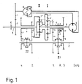
- Fig. 1 shows the concept of a transmission according to the patent DE-C-31 47 447.
- the four-shaft planetary gear consists of the planetary stage I with the sun gear 1 ', ring gear 2' and planet gear carrier s 'with the planet gears p' and the planetary stage II with the sun gear 1 '', ring gear 2 '' and planet gear carrier s '' with the planet gears p ''.
- the links s''and2' form the drive shaft 1, the links 1 'and 1''the shaft B for the connection of the constant volume displacement machine b, the link s' the slow-running coupling shaft E and the link 2''the high-speed coupling shaft A.
- the volume-adjustable displacement machine a stands above the gears 3; 4 with the drive shaft 1 in connection.
- the double-shift gear clutch Z1 can be 1st gear with the wheels 5; 6 or the 3rd gear with the wheels 7; 8 and the double-shift gear clutch Z2 can be the 2nd gear with the wheels 5 ';6' or connect the 4th gear with the wheels 7 ';8' to the output shaft 2. With wheel 9, sliding wheel 10 and wheel 11, the reverse gear can be realized.
- the vehicle is started with a friction clutch K.
- the coupling waves E; A alternately carry the power from the output to the output.
- 1st and 3rd gear belong to coupling shaft E and 2nd and 4th gear to coupling shaft A.
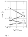
- Fig. 2 shows the curve related to the drive shaft of the speed of the output shaft n2 / n1 depending on the related displacement of the adjustable displacement machine a
- synchronous means the amount V a at which the clutch parts to be switched of the new gear have synchronous speeds.
- the diagram also shows the high-performance gears or coupling shafts.
- the gear change begins at synchronous speeds of the tooth clutch to be closed. If the gear-tooth clutches are closed by the old and new gear, the hydrostatic transmission generates the tension by means of a corresponding adjustment in the sense of the invention. To do this, the old high-performance coupling shaft must rotate somewhat faster than the new high-performance coupling shaft. After the tooth play has been consumed, the parts of the gear clutches run again with synchronous speeds.
- the numbers in Fig. 2 indicate the positions of the hydrostatic transmission necessary for this. When shifting up, the related bracing volumes are V a /
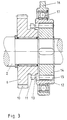
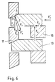
- Fig. 3 shows an idler gear 6 mounted on the output shaft 2 with a running toothing 10 and a coupling toothing 11, which can come into engagement with a ring 12 with internal toothing 13.
- a disk 14 with external toothing 15 connected to the output shaft 2 takes over the guidance of the ring 12.
- the shifting force is introduced via the shift fork 16 and the roller bearing 17.
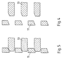
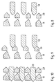
- FIG. 4 shows the unwound toothings 11 and 13 except and FIG. 5 in engagement.
- FIG. 7 represents a gear shift clutch analogous to FIG. 3, but which now has a synchronous lock.
- driver pins 19 are located on springs, which engage in recesses of the teeth 13. These pins 19 protrude into grooves 20 of the synchronizer ring 21 with a conical friction seat 22 and teeth 23.
- FIG. 8 shows the position of the toothings 11; 13; 23 with clutch open.
- the driving pins 19 push the synchronizer ring 23 onto the cone of wheel 6.
- the resulting frictional force rotates the synchronizer ring until the pins 19 stop against the edges of the grooves 20, so that, according to FIG. 9, the toothings 13 and 23 face each other stand and initially block switching. Only when the friction torque acting on the synchronizer ring is eliminated as a result of synchronous speeds, can the toothing 13 under the initial shifting force turn back the synchronizer ring 23. This will unlock it.
- the driving pins 19 are decoupled from the toothing 13 by the axial movement of the ring and no longer act.
- the toothings 13 and 11 find one another.
- the controller provides that the holding force is dependent on the path immediately after the synchronizer ring 23 has been turned back provided.
- the synchronizer ring 21 with the toothing 11 returns to the starting position in accordance with FIG. 8.
- the low initial shifting force reduces wear on the conical friction seat.
- the feed pump 24 delivers oil through the filter 25 and the check valve 26 through the pressure relief valve 27, which builds up the feed pressure in the lines 28 and 29. This is reduced by the pressure reducing valve 30, so that there is a small pressure in line 31.
- the lines 28 and 31 lead to a 3/2-way valve 32 which, via a 4/3-way valve 33, connects to the cylinder 34, the piston rod 35 of which is connected to the shift fork 16 (see FIG. 3; FIG. 7). so acted that either the pressure from line 31 or from line 28 builds up the switching force.
- the low pressure can also be used to provide a shifting force when shifting a gear that pushes the piston rod 35 to the neutral position
Landscapes
- Engineering & Computer Science (AREA)
- General Engineering & Computer Science (AREA)
- Mechanical Engineering (AREA)
- Structure Of Transmissions (AREA)
Claims (3)
- Transmission hydromécanique de vitesse se composant d'un engrenage planétaire à engrenages et à quatre arbres (I, II) et d'un engrenage hydrostatique (a, b) disposé parallèlement a celui-ci et réglable en continu ainsi que d'autres engrenages (3, 4, 5, 6, 5', 6', 7, 8, 7', 8', 9, 10, 11), des embrayages à denture (Z1, Z2) réalisant plusieurs vitesses pendant lesquelles l'engrenage hydrostatique (a, b) génère à chaque fois un réglage continu de la transmission de l'ensemble de l'engrenage, le changement de vitesse s'effectuant, pour des vitesses de rotation synchrones, sans charge et sans interruption de la force de traction et les machines volumétriques de l'engrenage hydrostatique (a, b) permutant leur fonctionnement en tant que pompe et moteur lors du changement de vitesse et l'embrayage à denture de la vitesse active étant maintenu en prise par l'intermédiaire d'un vérin hydraulique, caractérisée en ce que les dents des embrayages à denture (Z1, Z2) sont droites sur le flanc de montée et obliques sur le flanc arrière, en ce que, lors d'un changement de vitesse, après en avoir passé une nouvelle et avant d'avoir enlevé l'ancienne par un réglage de l'engrenage hydrostatique (a, b), par suite d'un serrage, l'embrayage à denture de l'ancienne vitesse porte sur le flanc avant et celui de la nouvelle sur le flanc arrière, en ce qu'après le serrage concernant l'ancienne vitesse, la force de blocage appliquée de l'extérieur est supprimée et en ce qu'un réglage ultérieur de l'engrenage hydrostatique (a, b) permet de supprimer le serrage, l'embrayage à denture de la nouvelle vitesse porte sur le flanc droit et celui de l'ancienne est désengrené de par le contact avec le flanc oblique.
- Transmission hydromécanique de vitesse selon la revendication 1, caractérisée en ce qu'avant de passer une nouvelle vitesse, la différence de vitesse de rotation divergeant de la vitesse de rotation synchrone est utilisée en tant que grandeur normale pour l'engrenage hydrostatique (a, b) pour permettre le changement de vitesse pour des vitesses de rotation synchrones.
- Transmission hydromécanique de vitesse selon les revendications 1 et 2, caractérisée en ce que les embrayages à denture sont utilisées avec un blocage de synchronisation et en ce que, lors de la fermeture destinée à l'activation du blocage, une faible force de commande est d'abord appliquée puis, après la suppression du blocage, une force élevée, en tant que force de serrage.
Applications Claiming Priority (2)
| Application Number | Priority Date | Filing Date | Title |
|---|---|---|---|
| DE3903877A DE3903877C1 (fr) | 1989-02-10 | 1989-02-10 | |
| DE3903877 | 1989-02-10 |
Publications (3)
| Publication Number | Publication Date |
|---|---|
| EP0382132A2 EP0382132A2 (fr) | 1990-08-16 |
| EP0382132A3 EP0382132A3 (fr) | 1991-08-28 |
| EP0382132B1 true EP0382132B1 (fr) | 1995-06-21 |
Family
ID=6373734
Family Applications (1)
| Application Number | Title | Priority Date | Filing Date |
|---|---|---|---|
| EP90102183A Expired - Lifetime EP0382132B1 (fr) | 1989-02-10 | 1990-02-03 | Transmission continue hydromécanique de vitesse avec accouplements dentés |
Country Status (4)
| Country | Link |
|---|---|
| US (1) | US5052986A (fr) |
| EP (1) | EP0382132B1 (fr) |
| JP (1) | JPH02300551A (fr) |
| DE (1) | DE3903877C1 (fr) |
Families Citing this family (36)
| Publication number | Priority date | Publication date | Assignee | Title |
|---|---|---|---|---|
| EP0564003A1 (fr) * | 1987-05-12 | 1993-10-06 | Jarchow, Friedrich, Prof. Dr.-Ing. | Boîte de vitesse hydrostatique-mécanique à réglage continu |
| US5186692A (en) * | 1989-03-14 | 1993-02-16 | Gleasman Vernon E | Hydromechanical orbital transmission |
| JPH0487751A (ja) * | 1990-07-31 | 1992-03-19 | Teijin Seiki Co Ltd | 運動変換機構 |
| DE4109884A1 (de) * | 1991-03-26 | 1992-10-01 | Claas Ohg | Steuerung einer verdraengermaschine eines hydrostatisch-mechanischen lastschaltgetriebes |
| JP3225071B2 (ja) * | 1992-01-13 | 2001-11-05 | マツダ株式会社 | 変速機のリバースブレーキ構造 |
| AT406035B (de) * | 1992-04-15 | 2000-01-25 | Schreiner Joachim | Fahrantrieb für eine arbeitsmaschine |
| DE4236671C1 (de) * | 1992-10-30 | 1993-11-18 | Jarchow Friedrich | Stufenlos wirkendes hydrostatisch-mechanisches Lastschaltgetriebe in kurzer Bauweise |
| US5522775A (en) * | 1993-10-18 | 1996-06-04 | Kabushiki Kaisha Komatsu Seisakusho | Speed change gear control system for hydrostatic-mechanical transmissions |
| US5931758A (en) * | 1998-04-08 | 1999-08-03 | General Dynamics Land Systems, Inc. | Simplified multi-range hydromechanical transmission for vehicles |
| US5951424A (en) * | 1998-06-08 | 1999-09-14 | Briceland & Associates Limited | Continuously variable power transmission |
| JP2969594B1 (ja) * | 1998-10-02 | 1999-11-02 | 株式会社プロジェット | 補助走行装置付き作業車両 |
| DE19924512C1 (de) * | 1999-05-28 | 2000-04-27 | Claas Industrietechnik Gmbh | Schalt-Zahnkupplung |
| US6565471B2 (en) * | 2000-12-19 | 2003-05-20 | Case Corporation | Continuously variable hydro-mechanical transmission |
| DE10122823B4 (de) * | 2001-05-11 | 2011-03-03 | Zf Friedrichshafen Ag | Leistungsverzweigungsgetriebe |
| DE10124352A1 (de) * | 2001-05-18 | 2002-11-21 | Zahnradfabrik Friedrichshafen | Mehrbereichsgetriebe für ein Kraftfahrzeug |
| DE10214478B4 (de) * | 2002-03-30 | 2004-04-15 | Zf Sachs Ag | Synchronisiereinrichtung für ein Doppelkupplungsgetriebe auf Grundlage wenigstens zweier Planetenradsätze und entsprechendes Doppelkupplungsgetriebe, sowie entprechender Kraftfahrzeug-Antriebsstrang |
| DE102004001929A1 (de) | 2004-01-14 | 2005-08-04 | Zf Friedrichshafen Ag | Hydrostatisch-mechanisches Leistungsverzweigungsgetriebe |
| JP2005291490A (ja) * | 2004-03-09 | 2005-10-20 | Nissan Motor Co Ltd | 変速機の同期装置 |
| US7241242B2 (en) * | 2004-10-28 | 2007-07-10 | General Motors Corporation | Two-mode compound-split hydraulic continuously variable transmission |
| US7530914B2 (en) * | 2005-06-03 | 2009-05-12 | Caterpillar Inc. | Hydromechanical transmission |
| US7530913B2 (en) * | 2005-06-03 | 2009-05-12 | Caterpillar Inc. | Multi-range hydromechanical transmission |
| US8070651B2 (en) * | 2007-12-07 | 2011-12-06 | Deere & Company | Work machine coast and brake control with an infinitely variable transmission |
| US7972240B2 (en) * | 2007-12-19 | 2011-07-05 | Deere & Company | Work machine with power limit control using an infinitely variable transmission |
| JP5169878B2 (ja) * | 2009-01-28 | 2013-03-27 | 三菱自動車工業株式会社 | デュアルクラッチ式変速機 |
| US8523724B2 (en) * | 2010-11-24 | 2013-09-03 | Caterpillar Inc. | Method of synchronizing in split torque continuously variable dual clutch transmission |
| DE102011077090B4 (de) * | 2011-06-07 | 2022-06-02 | Zf Friedrichshafen Ag | Verfahren zum Betreiben eines Fahrzeugantriebsstranges mit einer Antriebsmaschine und einer stufenlos leistungsverzweigten Getriebeeinrichtung |
| CN103635715B (zh) * | 2011-06-21 | 2017-05-17 | 沃尔沃建筑设备公司 | 用于控制动力分流式无级变速器的方法和动力分流式无级变速器 |
| JP5636475B2 (ja) * | 2013-07-31 | 2014-12-03 | ヤンマー株式会社 | 農作業車 |
| JP5636474B2 (ja) * | 2013-07-31 | 2014-12-03 | ヤンマー株式会社 | 農作業車 |
| CN104595431B (zh) * | 2015-01-28 | 2019-10-11 | 南京农业大学 | 一种大功率拖拉机液压机械无级变速器 |
| US10077828B2 (en) * | 2016-04-18 | 2018-09-18 | Caterpillar Inc. | Powertrain system for machine and method of operating same |
| CN107859722A (zh) * | 2017-10-19 | 2018-03-30 | 北京理工大学 | 一种模块化液压机械混合驱动装置 |
| JP6735306B2 (ja) * | 2018-03-30 | 2020-08-05 | 本田技研工業株式会社 | 変速装置 |
| AT521773B1 (de) * | 2018-11-13 | 2020-05-15 | Avl Commercial Driveline & Tractor Eng Gmbh | Antriebsstrang für ein Kraftfahrzeug |
| US11603890B2 (en) * | 2019-09-18 | 2023-03-14 | Ge Avio S.R.L. | Driveline engagement system |
| DE102019218091A1 (de) * | 2019-11-22 | 2021-05-27 | Zf Friedrichshafen Ag | Leistungsverzweigtes stufenloses Getriebe |
Family Cites Families (14)
| Publication number | Priority date | Publication date | Assignee | Title |
|---|---|---|---|---|
| DE143365C (fr) * | ||||
| DE195452C (fr) * | 1907-01-28 | 1900-01-01 | ||
| US3302475A (en) * | 1964-04-09 | 1967-02-07 | Massey Ferguson Inc | Transmission with lock out of overrun |
| US3580107A (en) * | 1968-10-21 | 1971-05-25 | Urs Systems Corp | Transmission |
| DE2655011C2 (de) * | 1976-12-04 | 1979-02-01 | Friedrich Prof. Dr.-Ing. 4300 Essen Jarchow | Stufenloses Koppelgetriebe |
| DE3147447C2 (de) * | 1981-12-01 | 1984-06-14 | Jarchow, Friedrich, Prof. Dr.-Ing., 4300 Essen | Hydrostatischmechanisches Stellkoppelgetriebe mit eingangsseitiger Leistungsverzweigung |
| SE8405095D0 (sv) * | 1984-10-11 | 1984-10-11 | Volvo Ab | Vexelladssynkronisering |
| JPS61274168A (ja) * | 1985-02-19 | 1986-12-04 | フリ−ドリヒ・ヤルコウ | 無段に変化するトルク分割複合出力用変位歯車 |
| JPS62137460A (ja) * | 1985-12-06 | 1987-06-20 | Meidensha Electric Mfg Co Ltd | トランスミツシヨンシンクロ調整装置 |
| EP0234136B1 (fr) * | 1986-02-24 | 1989-12-27 | Shimadzu Corporation | Transmission hydromécanique |
| JPS62234136A (ja) * | 1986-04-04 | 1987-10-14 | Konika Corp | カメラのパルス発生装置 |
| JP2586034B2 (ja) * | 1987-03-31 | 1997-02-26 | 株式会社島津製作所 | 無段変速装置 |
| DE3786996T2 (de) * | 1986-11-21 | 1993-12-23 | Shimadzu Corp | Stufenloses Getriebe. |
| DE3815780A1 (de) * | 1987-05-12 | 1988-12-01 | Jarchow Friedrich | Stufenlos wirkendes hydrostatischmechanisches lastschaltgetriebe |
-
1989
- 1989-02-10 DE DE3903877A patent/DE3903877C1/de not_active Expired - Lifetime
-
1990
- 1990-02-03 EP EP90102183A patent/EP0382132B1/fr not_active Expired - Lifetime
- 1990-02-09 JP JP2028622A patent/JPH02300551A/ja active Pending
- 1990-02-09 US US07/478,212 patent/US5052986A/en not_active Expired - Fee Related
Also Published As
| Publication number | Publication date |
|---|---|
| US5052986A (en) | 1991-10-01 |
| JPH02300551A (ja) | 1990-12-12 |
| EP0382132A3 (fr) | 1991-08-28 |
| DE3903877C1 (fr) | 1990-09-13 |
| EP0382132A2 (fr) | 1990-08-16 |
Similar Documents
| Publication | Publication Date | Title |
|---|---|---|
| EP0382132B1 (fr) | Transmission continue hydromécanique de vitesse avec accouplements dentés | |
| EP0557700B1 (fr) | Boîte de vitesse hydrostatique-mécanique à réglage continu | |
| EP1626206B1 (fr) | Transmission à division de puissance pour véhicules automobiles | |
| DE112004000874B4 (de) | Getriebe | |
| DE2633090C2 (de) | Hydrostatisch-mechanisches Getriebe mit Leistungsverzweigung für Kraftfahrzeuge | |
| EP0195452B1 (fr) | Transmission hybride commutable sous charge, réglable continûment à division de puissance et commande par groupes-relais | |
| DE4140865A1 (de) | Stufenlos einstellbares getriebe | |
| DE102007038942B4 (de) | Einwegkupplung mit Klauenkupplung und Sychronisiereinrichtung | |
| DE2328353C3 (de) | Stufenloses, leistungsverzweigendes hydrostatisch-mechanisches Getriebe | |
| DE2525888B2 (de) | Leistungsverzweigende Getriebeanordnung | |
| DE2026216B2 (de) | Verteilergetriebeanordnung fuer ein kraftfahrzeug | |
| DE3521932A1 (de) | Mehrgang-schaltgetriebe mit vorlegeaufbau | |
| DE3342047C2 (de) | Stufenlos einstellbares, leistungsverzweigendes Verbund-Lastschaltgetriebe | |
| DE2609282A1 (de) | Hydromechanisches getriebe, insbesondere fuer kraftfahrzeuge | |
| EP1015794A1 (fr) | Boite de vitesse | |
| DE69316383T2 (de) | Stufenloses verzweigungsgetriebe | |
| WO2021185643A1 (fr) | Transmission à variation continue à répartition de puissance | |
| EP1055835A1 (fr) | Embrayage à dents commutables | |
| DE102016213315B4 (de) | Stufenlos variables Getriebe | |
| DE3925732C1 (fr) | ||
| DE3903876C1 (en) | Transmission with a continuously variable action, a starting clutch and gears for hydrostatic-mechanical operation or hydrostatic operation | |
| DE4236671C1 (de) | Stufenlos wirkendes hydrostatisch-mechanisches Lastschaltgetriebe in kurzer Bauweise | |
| EP2169267B1 (fr) | Engrenage à roues coniques et anneau de friction | |
| DE4027724A1 (de) | Stufenloses hydrostatisch-mechanisches verzweigungsgetriebe, insbesondere fuer kraftfahrzeuge | |
| DE10201687B4 (de) | Toroidgetriebe mit Anlaufkupplung |
Legal Events
| Date | Code | Title | Description |
|---|---|---|---|
| PUAI | Public reference made under article 153(3) epc to a published international application that has entered the european phase |
Free format text: ORIGINAL CODE: 0009012 |
|
| AK | Designated contracting states |
Kind code of ref document: A2 Designated state(s): FR GB IT NL SE |
|
| 17P | Request for examination filed |
Effective date: 19901218 |
|
| PUAL | Search report despatched |
Free format text: ORIGINAL CODE: 0009013 |
|
| AK | Designated contracting states |
Kind code of ref document: A3 Designated state(s): FR GB IT NL SE |
|
| 17Q | First examination report despatched |
Effective date: 19931021 |
|
| GRAA | (expected) grant |
Free format text: ORIGINAL CODE: 0009210 |
|
| AK | Designated contracting states |
Kind code of ref document: B1 Designated state(s): FR GB IT NL SE |
|
| GBT | Gb: translation of ep patent filed (gb section 77(6)(a)/1977) |
Effective date: 19950622 |
|
| ET | Fr: translation filed | ||
| ITF | It: translation for a ep patent filed | ||
| PLBE | No opposition filed within time limit |
Free format text: ORIGINAL CODE: 0009261 |
|
| STAA | Information on the status of an ep patent application or granted ep patent |
Free format text: STATUS: NO OPPOSITION FILED WITHIN TIME LIMIT |
|
| 26N | No opposition filed | ||
| REG | Reference to a national code |
Ref country code: GB Ref legal event code: IF02 |
|
| PGFP | Annual fee paid to national office [announced via postgrant information from national office to epo] |
Ref country code: GB Payment date: 20020128 Year of fee payment: 13 |
|
| PGFP | Annual fee paid to national office [announced via postgrant information from national office to epo] |
Ref country code: FR Payment date: 20020221 Year of fee payment: 13 |
|
| PGFP | Annual fee paid to national office [announced via postgrant information from national office to epo] |
Ref country code: SE Payment date: 20020222 Year of fee payment: 13 |
|
| PGFP | Annual fee paid to national office [announced via postgrant information from national office to epo] |
Ref country code: NL Payment date: 20020226 Year of fee payment: 13 |
|
| PG25 | Lapsed in a contracting state [announced via postgrant information from national office to epo] |
Ref country code: GB Free format text: LAPSE BECAUSE OF NON-PAYMENT OF DUE FEES Effective date: 20030203 |
|
| PG25 | Lapsed in a contracting state [announced via postgrant information from national office to epo] |
Ref country code: SE Free format text: LAPSE BECAUSE OF NON-PAYMENT OF DUE FEES Effective date: 20030204 |
|
| PG25 | Lapsed in a contracting state [announced via postgrant information from national office to epo] |
Ref country code: NL Free format text: LAPSE BECAUSE OF NON-PAYMENT OF DUE FEES Effective date: 20030901 |
|
| GBPC | Gb: european patent ceased through non-payment of renewal fee | ||
| EUG | Se: european patent has lapsed | ||
| PG25 | Lapsed in a contracting state [announced via postgrant information from national office to epo] |
Ref country code: FR Free format text: LAPSE BECAUSE OF NON-PAYMENT OF DUE FEES Effective date: 20031031 |
|
| NLV4 | Nl: lapsed or anulled due to non-payment of the annual fee |
Effective date: 20030901 |
|
| REG | Reference to a national code |
Ref country code: FR Ref legal event code: ST |
|
| PG25 | Lapsed in a contracting state [announced via postgrant information from national office to epo] |
Ref country code: IT Free format text: LAPSE BECAUSE OF NON-PAYMENT OF DUE FEES;WARNING: LAPSES OF ITALIAN PATENTS WITH EFFECTIVE DATE BEFORE 2007 MAY HAVE OCCURRED AT ANY TIME BEFORE 2007. THE CORRECT EFFECTIVE DATE MAY BE DIFFERENT FROM THE ONE RECORDED. Effective date: 20050203 |