EP0378758A2 - Crémone - Google Patents
Crémone Download PDFInfo
- Publication number
- EP0378758A2 EP0378758A2 EP89119475A EP89119475A EP0378758A2 EP 0378758 A2 EP0378758 A2 EP 0378758A2 EP 89119475 A EP89119475 A EP 89119475A EP 89119475 A EP89119475 A EP 89119475A EP 0378758 A2 EP0378758 A2 EP 0378758A2
- Authority
- EP
- European Patent Office
- Prior art keywords
- lock
- slide
- bolt
- drive
- espagnolette
- Prior art date
- Legal status (The legal status is an assumption and is not a legal conclusion. Google has not performed a legal analysis and makes no representation as to the accuracy of the status listed.)
- Withdrawn
Links
Images
Classifications
-
- E—FIXED CONSTRUCTIONS
- E05—LOCKS; KEYS; WINDOW OR DOOR FITTINGS; SAFES
- E05C—BOLTS OR FASTENING DEVICES FOR WINGS, SPECIALLY FOR DOORS OR WINDOWS
- E05C9/00—Arrangements of simultaneously actuated bolts or other securing devices at well-separated positions on the same wing
- E05C9/02—Arrangements of simultaneously actuated bolts or other securing devices at well-separated positions on the same wing with one sliding bar for fastening when moved in one direction and unfastening when moved in opposite direction; with two sliding bars moved in the same direction when fastening or unfastening
- E05C9/021—Arrangements of simultaneously actuated bolts or other securing devices at well-separated positions on the same wing with one sliding bar for fastening when moved in one direction and unfastening when moved in opposite direction; with two sliding bars moved in the same direction when fastening or unfastening with rack and pinion mechanism
- E05C9/023—Arrangements of simultaneously actuated bolts or other securing devices at well-separated positions on the same wing with one sliding bar for fastening when moved in one direction and unfastening when moved in opposite direction; with two sliding bars moved in the same direction when fastening or unfastening with rack and pinion mechanism between a lock cylinder and the bar
-
- E—FIXED CONSTRUCTIONS
- E05—LOCKS; KEYS; WINDOW OR DOOR FITTINGS; SAFES
- E05B—LOCKS; ACCESSORIES THEREFOR; HANDCUFFS
- E05B15/00—Other details of locks; Parts for engagement by bolts of fastening devices
- E05B15/004—Lost motion connections
-
- E—FIXED CONSTRUCTIONS
- E05—LOCKS; KEYS; WINDOW OR DOOR FITTINGS; SAFES
- E05B—LOCKS; ACCESSORIES THEREFOR; HANDCUFFS
- E05B17/00—Accessories in connection with locks
- E05B17/0025—Devices for forcing the wing firmly against its seat or to initiate the opening of the wing
Definitions
- the invention relates to a locking cylinder-actuated espagnolette lock equipped with a slide bolt. According to the preamble of claim 1.
- a lock of the aforementioned type is known on the market, the drive rods starting from a drive rod connecting slide which is guided longitudinally in the lock housing. Whose longitudinal displacement caused by the closing rotation through the end wheel is transmitted to the slide bolt via an angle lever mounted around a fixed pin of the lock housing. There is a time delay in closing the slide bolt to the drive rods. A clearance in the form of a longitudinal recess on the connecting rod connecting piece is therefore provided between the angle lever and the connecting rod connecting piece. The angular lever and thus the thrust bolt are only taken along after this clearance has been passed. This means that the safety distance recommended by the customer is used up between the striker plate and the roller pin.
- the slide bolt extends into a z. B.
- the object of the invention is based on the object of designing an espagnolette lock of the type in question with a simple construction so that the sliding bolt displacement is not derived from that of the espagnolette.
- a generic drive rod lock of increased use value is created.
- the displacement of the slide bolt is now not derived from the movement of the connecting rods.
- the end wheel of the reduction gear having idler gears simultaneously displaces both the connecting rods and the slide bolt drive slide in opposite directions to the connecting rod.
- a sequential displacement of the drive rods and the slide bolt is possible in such a way that first the drive rod-side locking members come into engagement position on the first tour and then the slide bolt extends through the second tour.
- the corresponding locking elements ensure that the door is pulled forward a little so that the slide bolt can easily move into the associated strike plate opening.
- the slide bolt drive slide is displaced over a part of its displacement independently of the slide bolt and in opposite directions to the slide rod. Only after this predeterminable displacement path has been carried out is the sliding bolt carried along. There is therefore a positive control of the slide bolt, which is not interrupted during the closing phase.
- the safety distance between the roller pin and the striking plate can be dimensioned optimally.
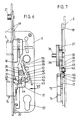
- the sliding bolt drive slide is designed as a space-saving angle piece to be accommodated in the lock housing. Its leg, which points approximately in the extension rod extension direction, forms the toothed rack that meshes with the end wheel. Rotation of the end wheel accordingly also leads to a displacement of the sliding bolt drive slide in the opposite direction to the drive rod.
- the slot section present in its leg, which receives the transmission pin, does not yet result in any sliding movement of the slide bolt. First when the transmission pin of the slide bolt tail reaches the other slot section of the other angle leg, the slide bolt is excluded. The course of this slot section therefore deviates from the direction of movement of the slide bolt, which course or inclination also determines the exclusion path.
- the slide lock drive slide is designed in such a way that it also allows a change operation.
- the corresponding slot section allows for the slight, oppositely directed displacement of the slide lock drive slide in the other direction.
- the ring gear forms the shoulder next to the one flank of its gap. With the corresponding direction of rotation of the toothed ring, this abuts against a corresponding area of the two-part change lever located in the movement path of the Schluter.
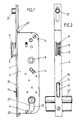
- the espagnolette lock has a lock cuff 1 with a lock base 2 attached to it. Parallel to this extends a lock cover 3 which overlaps the lock set-up. Fastening screws 4 serve to hold it, which engage in threaded holes in the lock case, not specified.
- a latch 5 is guided in the lock case housing. Their trap head 5 'penetrates an adapted passage opening 6 of the lock cuff 1. This position is maintained by a latch spring 5 ⁇ engaging latch spring 7.
- a nut 8 is mounted in the lock base 2 and lock cover 3. From this a nut arm 9 engages on the trap tail 5 ⁇ .
- the nut 8 is formed with a rotation limit stop 10. The latter is supported on a shoulder 11 of a bearing component 12, in which a compression spring (not shown) acting on a plunger 13 is accommodated, which plunger 13 loads the nut counterclockwise.
- a slide bolt 14 is guided. Whose bolt head 15 passes through a cross-section-adapted opening 16 of the lock cuff 1.
- the bolt head 15 continues in a push bolt tail 17, which is thinned compared to the bolt head 15. Otherwise, the push bolt tail 17 has an angular shape such that the end angle leg 17 'extends in the upward direction and projects above the bolt head 15.
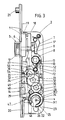
- connecting rod connecting piece 18 is shorter by the stroke of the connecting rods than the length of the lock case housing.
- the lock base 2 and lock cover 3 form a lock cylinder installation opening 22.
- This is adapted to a standard profile cylinder.
- a bearing block 23 is provided between the lock base 2 and the lock cover 3, which also has a recess (not designated in more detail) which corresponds to the installation opening 22.
- the bearing block 23 forms a bearing bore 24.
- the center point is designated M2 and lies above the center point M1, namely offset by the dimension x.
- the bearing bore 24 serves to receive a toothed ring 25 which has a radially oriented gap 26 which is open towards the edge and for engaging a locking bit (not shown) of a locking cylinder 27 to be inserted into the installation opening 22.
- the ring gear 25 meshes with two driven gear wheels 28, 29 arranged at the level of the slide bolt. This ensures that the toothed ring 25 meshes with at least one of the two driven gear wheels despite its gap 26.
- the driven gear wheels 28, 29 in turn mesh with an intermediate gear 30 having a larger number of teeth and mounted on the housing side, which carries on the same axis a further intermediate gear 31 with fewer teeth connected to it in a rotationally fixed manner.
- the pinion 35 meshes with a toothed rack 37 fixed to the connecting rod connecting piece. Rotation of the end wheel 34 accordingly leads to a displacement of the connecting rods 19, 20.
- a further toothed rack 38 runs , in such a way that the two toothed strips 37, 38 are at an acute angle to one another and that the pinion 35 of the end wheel 34 is arranged in the open angular space.
- the toothed rack 38 there is one leg 39 of a sliding bolt drive slider 40 which is angularly shaped in plan acute angle.
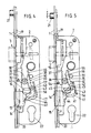
- the transmission pin 43 is located at the outer end of the leg 17 'of the slide bolt tail, projects beyond it and extends into a guide slot 45 in the slide bolt displacement direction of the lock base 2.
- the ring gear 25 has a radially extending shoulder 46 next to the one flank of its gap 26.
- the lower end 47 of a change lever 48 illustrated in two-dot chain lines lies in the turning circle of this shoulder 46.
- the end 47 is provided by the one change lever part 49 is formed, which is coupled to the other change lever part 51 via a pivot pin 50.
- This is supported by a bolt 52 of the bearing component 12 and engages the trap tail 5 ⁇ , namely by way of a pin / slot connection.
- To control the lower change lever part 49 is provided in this curve slot 53 into which a pin 54 of the connecting rod connector 18 is immersed.
- the slot section 44 could also be designed such that a further, downward slot section extends from the end thereof, so that in this way a push-back lock for the slide bolt 14 is created by the entry of the transmission pin 43 into this further slot section.
Landscapes
- Engineering & Computer Science (AREA)
- Mechanical Engineering (AREA)
- Lock And Its Accessories (AREA)
- Power-Operated Mechanisms For Wings (AREA)
Applications Claiming Priority (2)
| Application Number | Priority Date | Filing Date | Title |
|---|---|---|---|
| DE3901296 | 1989-01-18 | ||
| DE19893901296 DE3901296A1 (de) | 1989-01-18 | 1989-01-18 | Treibstangenschloss |
Publications (2)
| Publication Number | Publication Date |
|---|---|
| EP0378758A2 true EP0378758A2 (fr) | 1990-07-25 |
| EP0378758A3 EP0378758A3 (fr) | 1991-05-08 |
Family
ID=6372289
Family Applications (1)
| Application Number | Title | Priority Date | Filing Date |
|---|---|---|---|
| EP19890119475 Withdrawn EP0378758A3 (fr) | 1989-01-18 | 1989-10-20 | Crémone |
Country Status (2)
| Country | Link |
|---|---|
| EP (1) | EP0378758A3 (fr) |
| DE (1) | DE3901296A1 (fr) |
Cited By (5)
| Publication number | Priority date | Publication date | Assignee | Title |
|---|---|---|---|---|
| FR2687185A1 (fr) * | 1992-02-12 | 1993-08-13 | Vachette Sa | Serrure de porte assurant une fonction d'etancheite et une fonction de securite. |
| US6109666A (en) * | 1998-09-23 | 2000-08-29 | Ferco International, Ferrures Et Serrures De Batiment Sa | Espagnolette or espagnolette-lock for a door, French window or the like |
| EP0974721A3 (fr) * | 1998-07-23 | 2002-11-13 | Roto Frank Eisenwarenfabrik Aktiengesellschaft | Serrure à plusieurs pênes |
| CN102071844A (zh) * | 2009-11-25 | 2011-05-25 | 林响 | 多锁舌双快防盗锁 |
| US20140252780A1 (en) * | 2013-03-11 | 2014-09-11 | Samsung Sns Co., Ltd. | Door lock mortise |
Families Citing this family (3)
| Publication number | Priority date | Publication date | Assignee | Title |
|---|---|---|---|---|
| DE4014041A1 (de) * | 1990-05-02 | 1991-11-07 | Fuhr Carl Gmbh & Co | Schliesszylinderbetaetigbares treibstangenschloss |
| AT400062B (de) * | 1993-03-26 | 1995-09-25 | Roto Frank Eisenwaren | Mehrriegelschloss |
| ES2319354B1 (es) * | 2006-04-07 | 2009-09-30 | Talleres De Escoriaza S.A. | Cerradura de engranes con retencion para carpinteria metalica. |
Citations (2)
| Publication number | Priority date | Publication date | Assignee | Title |
|---|---|---|---|---|
| DE897520C (de) * | 1948-12-15 | 1953-11-23 | Guenther Obst | Stangenriegelschloss |
| DE3537786A1 (de) * | 1985-10-24 | 1987-04-30 | Fliether Karl Gmbh & Co | Treibstangenschloss |
Family Cites Families (5)
| Publication number | Priority date | Publication date | Assignee | Title |
|---|---|---|---|---|
| DE2919201C2 (de) * | 1979-05-12 | 1984-08-23 | Karl Fliether GmbH & Co, 5620 Velbert | Zahnradantrieb in einem schließzylinderbetätigbaren Treibstangenschloß |
| DE2929368C2 (de) * | 1979-07-20 | 1984-12-13 | Karl Fliether GmbH & Co, 5620 Velbert | Vorrichtung in einem Treibstangenschloß zum Verhindern des unbefugten Zurückdrückens einer Treibstange aus der Schließstellung |
| DE3148031A1 (de) * | 1981-12-04 | 1983-06-09 | Fa. Karl Fliether, 5620 Velbert | Zahnradantrieb in einem schliesszylinderbetaetigbaren treibstangenschloss mit schubriegel |
| DE3520862C2 (de) * | 1985-06-11 | 1995-02-23 | Fliether Karl Gmbh & Co | Treibstangenschloß |
| DE3901223A1 (de) * | 1988-01-18 | 1989-08-03 | Winkhaus Fa August | Treibstangenschloss |
-
1989
- 1989-01-18 DE DE19893901296 patent/DE3901296A1/de active Granted
- 1989-10-20 EP EP19890119475 patent/EP0378758A3/fr not_active Withdrawn
Patent Citations (2)
| Publication number | Priority date | Publication date | Assignee | Title |
|---|---|---|---|---|
| DE897520C (de) * | 1948-12-15 | 1953-11-23 | Guenther Obst | Stangenriegelschloss |
| DE3537786A1 (de) * | 1985-10-24 | 1987-04-30 | Fliether Karl Gmbh & Co | Treibstangenschloss |
Cited By (8)
| Publication number | Priority date | Publication date | Assignee | Title |
|---|---|---|---|---|
| FR2687185A1 (fr) * | 1992-02-12 | 1993-08-13 | Vachette Sa | Serrure de porte assurant une fonction d'etancheite et une fonction de securite. |
| ES2066709A2 (es) * | 1992-02-12 | 1995-03-01 | Vachette Sa | Cerradura de puerta que asegura una funcion de estanquidad y una funcion de seguridad. |
| EP0974721A3 (fr) * | 1998-07-23 | 2002-11-13 | Roto Frank Eisenwarenfabrik Aktiengesellschaft | Serrure à plusieurs pênes |
| US6109666A (en) * | 1998-09-23 | 2000-08-29 | Ferco International, Ferrures Et Serrures De Batiment Sa | Espagnolette or espagnolette-lock for a door, French window or the like |
| CN102071844A (zh) * | 2009-11-25 | 2011-05-25 | 林响 | 多锁舌双快防盗锁 |
| CN102071844B (zh) * | 2009-11-25 | 2013-03-20 | 林响 | 多锁舌双快防盗锁 |
| US20140252780A1 (en) * | 2013-03-11 | 2014-09-11 | Samsung Sns Co., Ltd. | Door lock mortise |
| US9284750B2 (en) * | 2013-03-11 | 2016-03-15 | Samsung Sds Co., Ltd. | Door mortise lock |
Also Published As
| Publication number | Publication date |
|---|---|
| DE3901296C2 (fr) | 1993-02-11 |
| EP0378758A3 (fr) | 1991-05-08 |
| DE3901296A1 (de) | 1990-07-26 |
Similar Documents
| Publication | Publication Date | Title |
|---|---|---|
| DE3505379C1 (de) | Treibstangenschloß | |
| EP0634552B1 (fr) | Clef avec pêne rotatif, spécialement comme serrure supplémentaire à barres coulissantes | |
| EP0358971B1 (fr) | Crémone | |
| DE4014041A1 (de) | Schliesszylinderbetaetigbares treibstangenschloss | |
| DE3901296C2 (fr) | ||
| DE4014046C2 (de) | Schließzylinderbetätigbares Treibstangenschloß | |
| DE3537786C2 (fr) | ||
| DE3148030C2 (fr) | ||
| DE3148031C2 (fr) | ||
| DE3213454C2 (de) | Wechselhebel-Betätigungsvorrichtung in einem zweitourigen schließzylinderbetätigbaren Treibstangenschloß | |
| EP0454959B1 (fr) | Serrure de barre coulissante manoeuvrable d'un barillet | |
| DE3520861A1 (de) | Rueckdruecksperre an treibstangenbeschlaegen, insbesondere schluesselbetaetigbaren treibstangenschloessern | |
| DE3731879C2 (de) | Schließzylinderbetätigbares Türschloß | |
| DE3901957C2 (de) | Treibstangenverschluß, insbesondere für Balkontüren | |
| EP0454960B1 (fr) | Cremone | |
| DE3213452C2 (de) | Wechselhebel-Betätigungsvorrichtung in einem schließzylinderbetätigbaren Treibstangenschloß | |
| DE3427712A1 (de) | Treibstangenschloss | |
| DE8532525U1 (de) | Treibstangenschloß mit Schließzylinder | |
| DE4014045C2 (de) | Einsteckschloß, insbesondere Treibstangenschloß | |
| DE3427713A1 (de) | Mehrtourig schliessendes treibstangenschloss | |
| DE4014040A1 (de) | Schloss, insbesondere treibstangenschloss | |
| EP0972900B1 (fr) | Crémone-serrure | |
| DE4302920C2 (de) | Schloß, insbesondere Einsteckschloß | |
| EP0806534B1 (fr) | Crémone | |
| EP0834633A1 (fr) | Crémone actionnée par une serrure cylindrique |
Legal Events
| Date | Code | Title | Description |
|---|---|---|---|
| PUAI | Public reference made under article 153(3) epc to a published international application that has entered the european phase |
Free format text: ORIGINAL CODE: 0009012 |
|
| AK | Designated contracting states |
Kind code of ref document: A2 Designated state(s): AT DE FR IT |
|
| PUAL | Search report despatched |
Free format text: ORIGINAL CODE: 0009013 |
|
| AK | Designated contracting states |
Kind code of ref document: A3 Designated state(s): AT DE FR IT |
|
| 17P | Request for examination filed |
Effective date: 19910521 |
|
| STAA | Information on the status of an ep patent application or granted ep patent |
Free format text: STATUS: THE APPLICATION IS DEEMED TO BE WITHDRAWN |
|
| 18D | Application deemed to be withdrawn |
Effective date: 19920501 |