EP0374612A1 - Spaltrohr-Elektromotor - Google Patents
Spaltrohr-Elektromotor Download PDFInfo
- Publication number
- EP0374612A1 EP0374612A1 EP89122608A EP89122608A EP0374612A1 EP 0374612 A1 EP0374612 A1 EP 0374612A1 EP 89122608 A EP89122608 A EP 89122608A EP 89122608 A EP89122608 A EP 89122608A EP 0374612 A1 EP0374612 A1 EP 0374612A1
- Authority
- EP
- European Patent Office
- Prior art keywords
- electric motor
- motor according
- canned electric
- stator
- windings
- Prior art date
- Legal status (The legal status is an assumption and is not a legal conclusion. Google has not performed a legal analysis and makes no representation as to the accuracy of the status listed.)
- Granted
Links
Images
Classifications
-
- H—ELECTRICITY
- H02—GENERATION; CONVERSION OR DISTRIBUTION OF ELECTRIC POWER
- H02K—DYNAMO-ELECTRIC MACHINES
- H02K17/00—Asynchronous induction motors; Asynchronous induction generators
-
- H—ELECTRICITY
- H02—GENERATION; CONVERSION OR DISTRIBUTION OF ELECTRIC POWER
- H02K—DYNAMO-ELECTRIC MACHINES
- H02K17/00—Asynchronous induction motors; Asynchronous induction generators
- H02K17/02—Asynchronous induction motors
- H02K17/30—Structural association of asynchronous induction motors with auxiliary electric devices influencing the characteristics of the motor or controlling the motor, e.g. with impedances or switches
-
- H—ELECTRICITY
- H02—GENERATION; CONVERSION OR DISTRIBUTION OF ELECTRIC POWER
- H02K—DYNAMO-ELECTRIC MACHINES
- H02K11/00—Structural association of dynamo-electric machines with electric components or with devices for shielding, monitoring or protection
- H02K11/20—Structural association of dynamo-electric machines with electric components or with devices for shielding, monitoring or protection for measuring, monitoring, testing, protecting or switching
-
- H—ELECTRICITY
- H02—GENERATION; CONVERSION OR DISTRIBUTION OF ELECTRIC POWER
- H02K—DYNAMO-ELECTRIC MACHINES
- H02K11/00—Structural association of dynamo-electric machines with electric components or with devices for shielding, monitoring or protection
- H02K11/30—Structural association with control circuits or drive circuits
- H02K11/33—Drive circuits, e.g. power electronics
-
- H—ELECTRICITY
- H02—GENERATION; CONVERSION OR DISTRIBUTION OF ELECTRIC POWER
- H02K—DYNAMO-ELECTRIC MACHINES
- H02K11/00—Structural association of dynamo-electric machines with electric components or with devices for shielding, monitoring or protection
- H02K11/30—Structural association with control circuits or drive circuits
- H02K11/35—Devices for recording or transmitting machine parameters, e.g. memory chips or radio transmitters for diagnosis
-
- H—ELECTRICITY
- H02—GENERATION; CONVERSION OR DISTRIBUTION OF ELECTRIC POWER
- H02K—DYNAMO-ELECTRIC MACHINES
- H02K3/00—Details of windings
- H02K3/04—Windings characterised by the conductor shape, form or construction, e.g. with bar conductors
- H02K3/12—Windings characterised by the conductor shape, form or construction, e.g. with bar conductors arranged in slots
-
- H—ELECTRICITY
- H02—GENERATION; CONVERSION OR DISTRIBUTION OF ELECTRIC POWER
- H02K—DYNAMO-ELECTRIC MACHINES
- H02K5/00—Casings; Enclosures; Supports
- H02K5/04—Casings or enclosures characterised by the shape, form or construction thereof
- H02K5/12—Casings or enclosures characterised by the shape, form or construction thereof specially adapted for operating in liquid or gas
- H02K5/128—Casings or enclosures characterised by the shape, form or construction thereof specially adapted for operating in liquid or gas using air-gap sleeves or air-gap discs
Definitions
- the invention relates to a canned electric motor, in particular for a pump with a stator lamination stack, which surrounds the gap (tube) pot and is penetrated by windings which protrude beyond the stator lamination stack, the can is closed at that end, and thus its Bottom forms, which is opposite the side on which the drive axis of the motor emerges.
- Canned motors for heating circulation pumps are known in a cylindrical design as well as disc rotors and ball motors.
- the stator is metallically separated from the rotor and sealed. In the cylindrical design, this is done through a metal can.
- the rotor is cooled within this tube by the pumped medium (heating water), which also lubricates and dampens the bearings.
- the manufacturing processes used for the constructions for stator and rotor differ only insignificantly in the stator production from processes for dry-running asynchronous motors.
- the degree of automation is essentially determined by the technical concept of the stator and its characteristic design features, such as the winding structure.
- the fact that the individual production stations differ greatly in the possibility of automating the required winding geometry makes it particularly difficult for stator production. This complicates the fully automatic chaining of individual production stations within the stator production.
- cylindrical stator windings with open and closed containment wells is also known today.
- the cylindrical stator windings are arranged so-called winding head caps or in a bandaged design over required air gaps to isolate them from the metallic can.
- the pull-in level of the winding (pull-in tool) or the position of the coils in the stator space must be selected in this case so that the slot space (coil) cannot be fully used electrically;
- the groove utilization is approx. 50% - 65%.
- the cause is the water volume of the canned or rotor space, which is also reduced due to the minimization, and the poor utilization of the groove.
- Machines of the power size according to the invention (less than 500W) and mechanical configuration have their greatest losses in the stator, so-called Cu or Electricity heat losses.
- the electrical insulation sections air or plastic
- the electrical insulation sections have a heat-insulating effect in the heat flow to the pumped medium.
- the object of the invention is to provide a canned electric motor with a higher degree of utilization with smaller dimensions and with an increase in the automation of the production by further linking of the production stations.
- the new concept differs from the previous one (cylindrical stator / rotor construction) in the winding structure of the stator winding, which is designed with an outwardly arched can bottom, especially as a spherical cap winding.
- a prerequisite for this version is the transition from a cylindrical can, open on both sides, to a so-called can.
- the end of the can must be dome-shaped to support the winding; i.e.
- the winding and containment can have the same shape.
- the winding is carried out with enamelable copper wire and mechanically homogeneously connected to the containment shell over the entire inner winding surface; ie the winding is baked radially and axially with the metallic containment shell.
- the electrical insulation takes place thereby over a powder coating (epoxy resin) of the containment shell.
- the coating is chosen so that a very good heat transfer from the stator winding to the can and pump chamber (wet chamber) is achieved; a better dissipation of the heat loss power of the motor to the fluid can be achieved.
- the winding By executing the dome-shaped winding (one-sided), the winding can be taken directly from the winding pull-in tool, since the finished winding geometry there almost corresponds to this shape. Elaborate bilateral preforming and intermediate molding measures are no longer necessary; Only a slight adjustment on the side of the end shield is sufficient.
- the stator with spherical cap winding is placed on the can-rotor assembly or fully assembled (or can without rotor).
- the containment can be used as a workpiece carrier for the entire subsequent processing of the motor or the pump (automatic interlinking). Even the still difficult to automate switching of the single-phase or three-phase windings of asynchronous machines can be carried out on the containment can used as a workpiece carrier.
- the pump can be assembled using the same workpiece carrier without a housing. Without motor housing for thermal installation and with motor housing for external standard pumps.
- the motor housing can be made of plastic and only has a protective function. The fully assembled motor housing can be mounted axially on the containment shell and contacted on the stator. This further simplifies assembly and disassembly.
- the housing is designed as a module, into which the terminal connection compartment was integrated at the same time. This also enables the inclusion of components such as switches, capacitors or complete control electronics with sensors, e.g. continuous speed control, differential pressure, temperature and volume flow control.
- the back of the housing can carry the nameplate data and at the same time a display with control panel for displaying and querying operating data.
- a data interface V24 or RS232 is provided in the housing module for diagnosis and status monitoring as well as for external central control (control room).
- the attachment of the housing to the side of the containment shell designed as a bearing shield is designed to be detachable for the customer and can be done e.g. defective electronics can be replaced.
- the electrical connections can be pluggable.
- the concept described above is not limited to a power unit size, but can be completely transferred to the canned motor series listed in the conventional design and manufacturing principle, as well as dry-running motors of low power with self-cooling only by convection. It can also be used with fans.
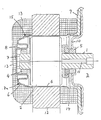
- the canned motor which can be used in particular for hot water heating in circulation pumps, has a hollow drive shaft 1 on which the rotor assembly 2 is fastened.
- the drive shaft 1 is rotatably mounted on the side facing away from the pump chamber 3 in a bearing 4 and on the facing side in a bearing 5.
- the rotor 2 is coaxially surrounded by a cylindrical containment shell 6, which is closed by a base 7 on the side facing away from the pump chamber.
- the bottom 7 can form an inwardly directed coaxial annular bead 8 which holds the bearing 4.
- a flange 9 is fastened or formed on the can 6, which carries the partition wall 10 between the interior of the can and the pump chamber 3.
- the bearing 5 is fixed and beyond this partition 10, the drive shaft 1 protrudes into the pump chamber 3 in order to carry the pump rotor, not shown, with this end.
- the interior of the containment shell 6 is flowed through by the pumped medium, which also flows through the coaxial cavity 11 of the drive shaft 1.
- the stator laminated core 12 is pushed on the outside, which has axially parallel grooves through which the winding wires run from the outer winding head 13 to the inner winding head 14.
- the bottom 7 of the containment shell 6 is curved outwards, and the windings of the winding head 13 lie tightly against the outside of this curved surface of the bottom.
- the bottom 7 thus forms a workpiece carrier and can have the shape of a hemisphere, a spherical section (spherical cap) or a spherical zone.
- the bottom of the containment shell is preferably less curved in the central area than in the adjoining edge area.
- the floor can be flat in the central area, in which case this flat surface is perpendicular to the axis of the motor.
- the bottom of the can can have the shape of a basket arch in section.
- the outer surface 7a of the cylindrical and the curved region of the containment shell carries a thin, electrically insulating layer 15, in particular a thin, electrically insulating lacquer, with a high thermal conductivity.
- the layer can have been produced by powder coating.
- the layer is an epoxy resin.
- the housing is designed as a module in which the terminal connection compartment is integrated, which contains components such as switches, capacitors or complete control electronics with sensors, continuous speed control, differential pressure, temperature and / or volume flow control.
- the back of the housing bears the nameplate data and / or at the same time a display with control panel for displaying and querying operating data.
- a data interface (V24 or RS232) is provided for diagnostics for condition monitoring and / or for external central control (master values) in the housing module.
- the fully assembled Motor housing is axially mounted on the containment shell 6 and contacted on the stator 12-14, so that a further simplification of assembly is achieved.
- the housing can be attached to the sides of the containment shell 6, which sides are designed in particular as a bearing plate, and can be replaced if, for example, defective electronics are used.
- the electrical connections can be plugged in for this purpose.
- the stator 12-14 is pushed onto the containment shell 6 until the in particular dome-shaped winding area of the winding head 13 rests on the containment shell base 7 and is baked thereon.
- the can 6 is used as a workpiece carrier for all subsequent processing of the motor or pump.
- the automatable interconnection of the single-phase or three-phase windings of asynchronous machines is also carried out on the can 6 used as the work back support.
- stator 12-14 the automatic contacting, the automatic caking of the winding and the electrical testing of the stator winding can be carried out on the containment shell 6.
- the pump With the can 6 as the workpiece holder, the pump is also installed without a motor housing for boiler installation or with a motor housing for external standard pumps.
- the manufacturing process takes place in the following steps: - punching and packaging the sheets for the stator package, - Surface coating of containment shell and stator package, (including grooves) - assembly of the chamber block, Winding and pulling the windings into the stator package, - easy preforming of the outer winding head 13, - assembly of the stator on the containment shell, - contacting and checking the windings, light pressing of the windings of the winding head 13 on the can bottom and caking of the windings on the floor, - final inspection of the structural unit manufactured up to this point, - assembly of the motor housing, - Attach the motor housing to the pump housing.
Abstract
Description
- Die Erfindung betrifft einen Spaltrohr-Elektromotor, insbesondere für eine Pumpe mit einem Statorblechpaket, das den Spalt(rohr)topf umgibt und von Wicklungen durchdrungen ist, die das Statorblechpaket zu beiden Seiten überragen, wobei der Spalttopf an demjenigen Ende geschlossen ist, und damit seinen Boden bildet, das der Seite gegenüberliegt, an der die Antriebsachse des Motors heraustritt.
- Spaltrohrmotoren für Heizungsumwälzpumpen sind in zylindrischer Bauweise sowie als Scheibenläufer und als Kugelmotor bekannt. Bei diesen Konstruktionen ist der Stator vom Rotor metallisch getrennt und abgedichtet. In der zylindrischen Bauweise erfolgt dies durch ein Metallspaltrohr. Der Rotor wird innerhalb dieses Rohres durch das Fördermedium (Heizungswasser) gekühlt, das auch die Lagerung schmiert und dämpft.
- Die für die Konstruktionen angewandten Fertigungsverfahren für Stator und Rotor unterscheiden sich in der Statorfertigung nur unwesentlich von Verfahren für Trockenläufer-Asynchronmotoren. Der Automatisierungsgrad wird hierbei wesentlich vom technischen Konzept des Stators und dessen charakteristischen Konstruktionsmerkmalen bestimmt, wie z.B. durch daen Wicklungsaufbau. Erschwerend wirkt speziell bei der Statorfertigung, daß die einzelnen Fertigungsstationen sich in der Möglichkeit zur Automatisierung der erforderlichen Wicklungsgeometrie stark unterscheiden. Dies erschwert vor allem die vollautomatische Verkettung einzelner Fertigungsstationen innerhalb der Statorfertigung.
- Bekannt ist heute ebenfalls der Einsatz von zylindrischen Statorwicklungen mit offenen und geschlossenen Spalttöpfen. Die zylindrischen Statorwicklungen sind dabei mit sogenannten Wickelkopfkappen oder in bandagierter Ausführung über erforderliche Luftstrecken gegen das metallische Spaltrohr isolierend angeordnet. Die Einziehebene der Wicklung (Einziehwerkzeug) oder die Position der Spulen im Statorraum muß in diesem Fall so gewählt werden, daß der Nutraum (Spule) elektrisch nicht voll genutzt werden kann; Die Nutausnutzung beträgt ca. 50% - 65%. Eine weitere Minimierung der Motorabmessungen unter Beibehaltung einer zylindrischen Wicklung, z.B. mit Wickelkopfkappen oder mit Bandagierung zur Einhaltung von Luftstrecken gegenüber dem Spaltrohr, Lagerschild oder Motorgehäuse stößt an Grenzen der thermischen Motorbelastung oder der elektromagnetischen Ausnutzung der Maschine. Die Ursache ist in dem durch die Minimierung ebenfalls reduzierten Wasservolumen des Spaltrohr- oder Rotorraumes zu sehen, sowie der schlechten Nutausnutzung. Maschinen der erfindungsgemäßen Leistungsgröße (kleiner 500W) und mechanischen Konfiguration haben ihre größten Verluste im Ständer, sogenannte Cu- oder Stromwärmeverluste. Bei den bisherigen Konstruktionsprinzipien wirken die elektrischen Isolationsstrecken (Luft oder Kunststoff) im Wärmefluß zum Fördermedium wärmeisolierend.
- Aufgabe der Erfindung ist es einen Spaltrohr-Elektromotor zu schaffen mit einem höheren Ausnutzungsgrad bei kleineren Abmessungen und mit einer Steigerung der Automatisierung der Herstellung durch weitere Verkettung der Fertigungsstationen.
- Diese Aufgabe wird erfindungsgemäß dadurch gelöst, daß der Boden des Spalttopfes nach außen gewölbt ist und die Wicklungen einer Seite des Statorblechpaketes an der gewölbten Fläche des Bodens außen anliegen.
- Das neue Konzept unterscheidet sich von dem bisherigen (zylindrische Stator-/Rotorbauweise) durch den Wicklungsaufbau der Statorwicklung, ausgeführt mit einem nach außen gewölbten Spalttopfboden, insbesondere als Kalottenwicklung. Voraussetzung für diese Ausführung ist der Übergang von einem zylindrischen, beidseitig geöffneten Spaltrohr in einen sogenannten Spalttopf. Das Ende des Spalttopfes muß dabei zur Abstützung der Wicklung kalottenförmig ausgeführt werden; d.h. Wicklung und Spalttopf sind konturengleich.
- Mit der kalottenförmigen Wicklung in Verbindung mit dem geschlossenen Spalttopf können diese Probleme eliminiert werden. Die Wicklung wird dabei mit einem verbackungsfähigen Kupferlackdraht ausgeführt und mechanisch über die gesamte innere Wicklungsoberfläche mit dem Spalttopf homogen verbunden; d.h. die Wicklung wird mit dem metallischen Spalttopf radial wie axial flächig anliegend, verbacken. Die elektrische Isolierung erfolgt dabei über eine Pulverbeschichtung (Epoxydharz) des Spalttopfes. Die Beschichtung wird so gewählt, daß ein sehr guter Wärmeübergang von der Statorwicklung zum Spaltrohr- und Pumpenraum (Naßraum) erreicht wird; damit kann eine bessere Abfuhr der Wärmeverlustleistung des Motors an das Fördermedium erzielt werden. Dieses neue Konstruktionsprinzip öffnet dabei weitere Möglichkeiten der Fertigungsrationalisierung durch Reduktion der bisherigen Fertigungsschritte und durch stärkere Verkettung der einzelnen Fertigungsstationen. Durch die Ausführung der Wicklung in Kalottenform (einseitig) kann die Wicklung direkt aus dem Wicklungseinziehwerkzeug übernommen werden, da die Wicklungs-Fertiggeometrie dort fast dieser Form entspricht. Aufwendige beidseitige Vorform- und Zwischenformmaßnahmen entfallen; Nur ein leichtes Anpaßformen auf der Lagerschildseite reicht aus. Auf die Baugruppe Spalttopf-Rotor-oder fertigmontiert (oder Spalttopf ohne Rotor) wird der Stator mit Kalottenwicklung aufgesetzt. Der Spalttopf kann dabei als Werkstückträger für die gesamte nachfolgende Weiterverarbeitung des Motors oder der Pumpe verwendet werden (automatische Verkettung). Selbst das immer noch schwierig automatisierbare Verschalten der Einphasen- oder Dreiphasenwicklungen von Asynchronmaschinen kann auf dem als Werkstückträger benutzten Spalttopf vorgenommen werden.
- Weiter integrierte Fertigungsschritte mit dem Spalttopf-Werkstückträger sind das Fertigmontieren des Stators auf dem Spalttopf (Statorsitz), das automatische Kontaktieren, das automatische Verbacken der Wicklung und elektrisches Prüfen der Statorwicklung bei komplettiertem Spalttopf, d.h. einschließlich der Baugruppe Rotor ist damit auch die vollständige elektrische Endkontrolle des Motors möglich. Nach diesem Fertigungsablauf des Motors ohne Gehäuse kann mit dem gleichen Werkstückträger die Pumpenmontage erfolgen. Ohne Motorgehäuse für Thermeneinbau und mit Motorgehäuse für externe Standardpumpen. Das Motorgehäuse kann in Kunststoff ausgeführt werden und hat nur noch eine Schutzfunktion.
Das fertigmontierte Motorgehäuse kann axial auf dem Spalttopf montiert und am Stator kontaktiert werden. Damit wird eine weitere Montage- und Demontagevereinfachung erzielt. - Bei dem Motorkonzept mit Kalottenwicklung wird das Gehäuse als Modul gestaltet, in das gleichzeitig der Klemmenanschlußraum integriert wurde. Dies ermöglicht ebenso die Aufnahme von Komponenten, wie Schalter, Kondensator oder komplette Regelelektronik mit Sensorik, z.B. kontinuierliche Drehzahlregelung, Differenzdruck-, Temperatur- und Volumenstromregelung. Die Gehäuserückseite kann dabei die Typenschilddaten und gleichzeitig ein Display mit Bedienfeld tragen zur Anzeige und Abfrage von Betriebsdaten. Für Diagnose und Zustandsüberwachung, sowie für externe zentrale Steuerung (Leitwarte) ist im Gehäusemodul eine Datenschnittstelle V24 oder RS232 vorgesehen. Die Befestigung des Gehäuses an der als Lagerschild ausgebildeten Seite des Spalttopfes ist für den Kunden lösbar ausgeführt und kann bei z.B. schadhafter Elektronik ausgetauscht werden. Die elektrischen Verbindungen können steckbar sein.
- Das vorstehend beschriebene Konzept beschränkt sich nicht auf eine Leistungsbaugröße, sondern kann vollständig auf die im herkömmlichen Konstruktions- und Fertigungsprinzip angeführte Spaltrohrmotorenreihe übertragen werden, sowie Trockenläufermotore kleiner Leistung mit Eigenkühlung nur durch Konvektion. Es ist auch bei Ventilatoren anwendbar.
- Vorteilhafte Ausgestaltungen der Erfindung sind in den Unteransprüchen aufgeführt. Ein Ausführungsbeispiel der erfindungsgemäßen Motors ist in der Zeichnung in einem axialen Schnitt dargestellt und wird im folgenden näher beschrieben.
Der insbesondere für Warmwasserheizungen bei Umwälzpumpen einsetzbare Spaltrohrmotor weist eine hohle Antriebsachse 1 auf, auf der das Rotorpaket 2 befestigt ist. Die Antriebsachse 1 ist auf der dem Pumpenraum 3 abgewandten Seite in einem Lager 4 und auf der zugewandten Seite in einem Lager 5 drehbar befestigt. Der Rotor 2 ist koaxial von einem zylindrischen Spalttopf 6 umgeben, der auf der dem Pumpenraum abgewandten Seite von einem Boden 7 verschlossen ist. Der Boden 7 kann einen nach innen gerichteten koaxialen Ringwulst 8 bilden, der das Lager 4 hält. - Auf der dem Pumpenraum 3 zugewandten Seite ist am Spalttopf 6 ein Flansch 9 befestigt oder angeformt, der die Trennwand 10 zwischen dem Inneren des Spalttopfes und dem Pumpenraum 3 trägt. In dieser Trennwand 10 ist das Lager 5 befestigt und über diese Trennwand 10 hinaus ragt die Antriebsachse 1 in den Pumpenraum 3 hinein, um mit diesem Ende den nicht dargestellten Pumpenrotor zu tragen. Das Innere des Spalttopfes 6 ist vom Fördermedium durchflossen, das auch durch den koaxialen Hohlraum 11 der Antriebsachse 1 fließt.
- Im etwa mittleren, zylindrischen Bereich des Spalttopfes 6 ist außen das Stator-Blechpaket 12 aufgeschoben, das achsparallele Nuten besitzt, durch die die Wicklungsdrähte vom äußeren Wicklungskopf 13 zum inneren Wicklungskopf 14 verlaufen. Der Boden 7 des Spalttopfes 6 ist nach außen gewölbt, und die Wicklungen des Wicklungskopfes 13 liegen außen an dieser gewölbten Fläche des Bodens dicht an.
- Hierzu müssen die Wicklungen des Kopfes 13 nur leicht verformt werden, so daß sie im wesentlichen eine gewölbte Form beibehalten, die sie nach dem Wickeln haben. Der Boden 7 bildet somit einen Werkstückträger und kann die Form einer Halbkugel, eines Kugelabschnitts (Kalotte) oder einer Kugelzone besitzen. Vorzugsweise ist der Boden des Spalttopfes im mittleren Bereich geringer gekrümmt als im daran anschließenden Randbereich. Insbesondere kann der Boden im mittleren Bereich eben sein, wobei dann diese ebene Fläche rechtwinklig zur Achse des Motors steht. Ferner kann der Boden des Spalttopfes im Schnitt die Form eines Korbbogens haben.
- Ein sehr fester Halt der Wicklungen ist dann gegeben, wenn die Wicklungen am Boden 7 außen angebacken bzw. angeklebt sind. Die Außenfläche 7a des zylindrischen und des gewölbten Bereiches des Spalttopfes trägt hierzu eine dünne, elektrisch isolierende Schicht 15, insbesondere einen dünnen, elektrisch isolierenden Lack, mit einer hohen Wärmeleitfähigkeit. Die Schicht kann durch Pulverbeschichtung erzeugt worden sein. Insbesondere ist die Schicht ein Epoxydharz.
- Das Gehäuse ist als Modul gestaltet, in das der Klemmenanschlußraum integriert ist, der Komponenten wie Schalter, Kondensator oder komplette Regelelektronik mit Sensorik, kontinuierlicher Drehzahlregelung, Differenzdruck-, Temperatur- und/oder Volumenstromregelung enthält. Die Gehäuserückseite trägt die Typenschilddaten und/oder gleichzeitig ein Display mit Bedienfeld zur Anzeige und Abfrage von Betriebsdaten. Für Diagnosen für Zustandsüberwachung und/oder für externe zentrale Steuerung (Leitwerte) im Gehäusemodul ist eine Datenschnittstelle (V24 oder RS232) vorgesehen. Das fertig montierte Motorgehäuse ist axial auf dem Spalttopf 6 montiert und am Stator 12-14 kontaktiert, so daß eine weitere Montagevereinfachung erzielt wird. Die Befestigung des Gehäuses an den insbesondere als Lagerschild ausgebildeten Seiten des Spalttopfes 6 ist lösbar und kann bei z.B. schadhafter Elektronik ausgetauscht werden. Hierzu sind die elektrischen Verbindungen steckbar. Auf dem Spalttopf 6 wird der Stator 12-14 aufgeschoben, bis der insbesondere kalottenförmige Wicklungsbereich des Wicklungskopfes 13 auf dem Spalttopfboden 7 aufliegt und auf diesem verbacken wird. Der Spalttopf 6 wird als Werkstückträger für die gesamte nachfolgende Weiterverarbeitung des Motors oder Pumpe verwendet. Auch wird das automatisierbare Verschalten der Einphasen- oder Dreiphasenwicklungen von Asynchronmaschinen auf dem als Werkstrückträger benutzten Spalttopf 6 vorgenommen. Ferner kann auf dem Spalttopf 6 das Fertigmontieren des Stators 12-14, das automatische Kontaktieren, das automatische Verbacken der Wicklung und elektrische Prüfen der Statorwicklung erfolgen. Mit dem Spalttopf 6 als Werkstückträger erfolgt auch die Pumpenmontage ohne Motorgehäuse für Heizkesseleinbau oder mit Motorgehäuse für externe Standardpumpen.
- Das Herstellungsverfahren läuft in folgenden Schritten ab:
- Stanzen und Paketieren der Bleche für das Statorpaket,
- Oberflächenbeschichtung von Spalttopf und Statorpaket, (einschließlich Nuten)
- Montage des Kammerblocks,
- Wickeln und Einziehen der Wicklungen in das Statorpaket,
- leichtes Vorformen des äußeren Wicklungskopfes 13,
- Montage des Stators auf dem Spalttopf,
- Kontaktieren und Prüfen der Wicklungen,
- leichtes Andrücken der Wicklungen des Wicklungskopfes 13 am Spalttopfboden und Verbacken der Wicklungen am Boden,
- Endkontrolle der bis hier hin hergestellten Baueinheit,
- Montage des Motorengehäuses,
- Befestigen des Motorengehäuses am Pumpengehäuse.
Claims (23)
Priority Applications (1)
| Application Number | Priority Date | Filing Date | Title |
|---|---|---|---|
| AT89122608T ATE95954T1 (de) | 1988-12-23 | 1989-12-07 | Spaltrohr-elektromotor. |
Applications Claiming Priority (2)
| Application Number | Priority Date | Filing Date | Title |
|---|---|---|---|
| DE3843477 | 1988-12-23 | ||
| DE3843477A DE3843477A1 (de) | 1988-12-23 | 1988-12-23 | Spaltrohr-elektromotor |
Publications (2)
| Publication Number | Publication Date |
|---|---|
| EP0374612A1 true EP0374612A1 (de) | 1990-06-27 |
| EP0374612B1 EP0374612B1 (de) | 1993-10-13 |
Family
ID=6370003
Family Applications (1)
| Application Number | Title | Priority Date | Filing Date |
|---|---|---|---|
| EP89122608A Expired - Lifetime EP0374612B1 (de) | 1988-12-23 | 1989-12-07 | Spaltrohr-Elektromotor |
Country Status (7)
| Country | Link |
|---|---|
| US (1) | US5034644A (de) |
| EP (1) | EP0374612B1 (de) |
| JP (1) | JPH088752B2 (de) |
| KR (1) | KR920000682B1 (de) |
| AT (1) | ATE95954T1 (de) |
| DE (2) | DE3843477A1 (de) |
| ES (1) | ES2044031T3 (de) |
Cited By (2)
| Publication number | Priority date | Publication date | Assignee | Title |
|---|---|---|---|---|
| EP1028513A2 (de) * | 1999-02-12 | 2000-08-16 | WILO GmbH | Polschenkelträger |
| EP2110928A1 (de) | 2008-04-19 | 2009-10-21 | Grundfos Management A/S | Statorgehäusebaugruppe für einen Spaltrohrmotor |
Families Citing this family (19)
| Publication number | Priority date | Publication date | Assignee | Title |
|---|---|---|---|---|
| DE3834668A1 (de) * | 1988-10-12 | 1990-04-19 | Klein Schanzlin & Becker Ag | Druckfest gekapselter spaltrohrmotor |
| JP2525512B2 (ja) * | 1990-11-29 | 1996-08-21 | 矢崎総業株式会社 | スイッチ端子およびスイッチ端子付きコネクタ |
| DE4113198A1 (de) * | 1991-04-23 | 1992-10-29 | Oplaender Wilo Werk Gmbh | Elektromotor, insbesondere spaltrohrmotor fuer eine kreiselpumpe oder einen luefter |
| DE9402763U1 (de) * | 1994-02-19 | 1994-04-07 | Wilo Gmbh | Spalttopf einer Kreiselpumpe |
| DE4438132A1 (de) † | 1994-10-27 | 1996-05-02 | Wilo Gmbh | Spaltrohrpumpe |
| US5627420A (en) * | 1994-12-16 | 1997-05-06 | Westinghouse Electric Corporation | Pump powered by a canned electric motor having a removable stator cartridge |
| US5767596A (en) * | 1996-10-03 | 1998-06-16 | General Electric Company | Dynamoelectric machine and processes for making the same |
| DE19824345A1 (de) * | 1998-06-02 | 1999-12-09 | Wilo Gmbh | Spaltrohrpumpe mit Wicklungsträger |
| EP0989658A1 (de) * | 1998-09-28 | 2000-03-29 | The Swatch Group Management Services AG | Flussigkeitsgekühlter elektrischen Asynchronmaschine |
| US6884043B2 (en) * | 2002-02-28 | 2005-04-26 | Standex International Corp. | Fluid circulation path for motor pump |
| US6847140B2 (en) * | 2002-02-28 | 2005-01-25 | Standex International Corp. | Fluid barrier for motor rotor |
| DE102004048557A1 (de) * | 2004-10-04 | 2006-04-06 | Aweco Appliance Systems Gmbh & Co. Kg | Flüssigkeitspumpe |
| US20120328461A1 (en) * | 2008-06-11 | 2012-12-27 | AquaMotion, Inc. | Motor pump bearing |
| US8083500B1 (en) * | 2008-06-11 | 2011-12-27 | AquaMotion, Inc. | Motor pump |
| US8585378B2 (en) * | 2009-06-25 | 2013-11-19 | Nidec Motor Corporation | Integrated endshield and pump volute for an electric pump and method of forming an electric pump |
| JP5672193B2 (ja) * | 2011-08-08 | 2015-02-18 | トヨタ自動車株式会社 | 回転電機 |
| JP6040119B2 (ja) * | 2013-08-12 | 2016-12-07 | アスモ株式会社 | ヨークハウジング、モータ及びヨークハウジングの製造方法 |
| WO2018171217A1 (zh) * | 2017-03-20 | 2018-09-27 | 天纳克(苏州)排放系统有限公司 | 集成装置、尾气后处理系统以及控制方法 |
| DE102019102318A1 (de) * | 2019-01-30 | 2020-07-30 | Nidec Gpm Gmbh | Pumpe aufweisend einen Elektromotor mit Steckeranbindung in Form eines Zwischenringes |
Citations (2)
| Publication number | Priority date | Publication date | Assignee | Title |
|---|---|---|---|---|
| EP0095958A1 (de) * | 1982-05-27 | 1983-12-07 | Pompes Salmson | Elektrischer Motor mit bewickeltem Stator und Verfahren zu seiner Herstellung |
| FR2533976A1 (fr) * | 1982-10-05 | 1984-04-06 | Electro Hydraulique Seh | Motopompe a moteur elecrique a rotor noye |
Family Cites Families (11)
| Publication number | Priority date | Publication date | Assignee | Title |
|---|---|---|---|---|
| US1875207A (en) * | 1930-12-11 | 1932-08-30 | Vincent G Apple | Alternating current motor |
| US2972308A (en) * | 1957-03-12 | 1961-02-21 | Thompson Ramo Wooldridge Inc | Sealed stator submerged electric fuel pump |
| CH356023A (fr) * | 1959-02-17 | 1961-07-31 | Faere Armaturfabrik Ab | Pompe centrifuge à commande électromotrice |
| CH372928A (de) * | 1959-06-01 | 1963-10-31 | Spring Fritz | Aus Flüssigkeitspumpe und an ihr anmontiertem Elektromotor bestehendes Aggregat |
| FR1394963A (fr) * | 1964-02-21 | 1965-04-09 | Julien & Mege | Perfectionnement aux moteurs électriques asynchrones |
| BE788026A (fr) * | 1971-08-26 | 1973-02-26 | Siemens Ag | Procede et dispositif d'introduction dirigee de matieres de dopage dansdes cristaux semiconducteurs lors d'une fusion par zones sans creuset |
| JPS60174448U (ja) * | 1984-04-26 | 1985-11-19 | 株式会社東芝 | 誘導電動機 |
| DE3538507A1 (de) * | 1984-11-02 | 1986-06-05 | Karsten Dipl.-Ing. 7148 Remseck Laing | Elektromotor mit sphaerischem spalt |
| US4651039A (en) * | 1985-02-08 | 1987-03-17 | Mitsubishi Denki Kabushiki Kaisha | Molded-type underwater motor |
| JPS61241494A (ja) * | 1985-04-16 | 1986-10-27 | Sanyo Electric Co Ltd | ポンプ |
| DE3631710C2 (de) * | 1986-09-18 | 1995-08-31 | Birger Laing | Umschlagbare Kreiselpumpen-Elektromotoren-Einheit |
-
1988
- 1988-12-23 DE DE3843477A patent/DE3843477A1/de not_active Ceased
-
1989
- 1989-12-07 ES ES89122608T patent/ES2044031T3/es not_active Expired - Lifetime
- 1989-12-07 DE DE89122608T patent/DE58905907D1/de not_active Expired - Fee Related
- 1989-12-07 AT AT89122608T patent/ATE95954T1/de not_active IP Right Cessation
- 1989-12-07 EP EP89122608A patent/EP0374612B1/de not_active Expired - Lifetime
- 1989-12-19 US US07/454,777 patent/US5034644A/en not_active Expired - Fee Related
- 1989-12-21 JP JP1329753A patent/JPH088752B2/ja not_active Expired - Fee Related
- 1989-12-22 KR KR1019890019242A patent/KR920000682B1/ko not_active IP Right Cessation
Patent Citations (2)
| Publication number | Priority date | Publication date | Assignee | Title |
|---|---|---|---|---|
| EP0095958A1 (de) * | 1982-05-27 | 1983-12-07 | Pompes Salmson | Elektrischer Motor mit bewickeltem Stator und Verfahren zu seiner Herstellung |
| FR2533976A1 (fr) * | 1982-10-05 | 1984-04-06 | Electro Hydraulique Seh | Motopompe a moteur elecrique a rotor noye |
Cited By (6)
| Publication number | Priority date | Publication date | Assignee | Title |
|---|---|---|---|---|
| EP1028513A2 (de) * | 1999-02-12 | 2000-08-16 | WILO GmbH | Polschenkelträger |
| EP1028513A3 (de) * | 1999-02-12 | 2000-12-20 | WILO GmbH | Polschenkelträger |
| EP2110928A1 (de) | 2008-04-19 | 2009-10-21 | Grundfos Management A/S | Statorgehäusebaugruppe für einen Spaltrohrmotor |
| WO2009143918A2 (de) * | 2008-04-19 | 2009-12-03 | Grundfos Management A/S | Statorgehäusebaugruppe für einen spaltrohrmotor |
| WO2009143918A3 (de) * | 2008-04-19 | 2010-04-01 | Grundfos Management A/S | Statorgehäusebaugruppe für einen spaltrohrmotor |
| US9225221B2 (en) | 2008-04-19 | 2015-12-29 | Grundfos Management A/S | Stator housing assembly for a canned motor |
Also Published As
| Publication number | Publication date |
|---|---|
| ES2044031T3 (es) | 1994-01-01 |
| ATE95954T1 (de) | 1993-10-15 |
| DE58905907D1 (de) | 1993-11-18 |
| US5034644A (en) | 1991-07-23 |
| KR920000682B1 (ko) | 1992-01-20 |
| JPH088752B2 (ja) | 1996-01-29 |
| DE3843477A1 (de) | 1990-06-28 |
| EP0374612B1 (de) | 1993-10-13 |
| KR900011106A (ko) | 1990-07-11 |
| JPH02266841A (ja) | 1990-10-31 |
Similar Documents
| Publication | Publication Date | Title |
|---|---|---|
| EP0374612B1 (de) | Spaltrohr-Elektromotor | |
| DE112015002343B4 (de) | Wechselrichterintegrierte Motorvorrichtung | |
| EP3411940B1 (de) | Elektromotor für eine fluidpumpe, modulare motorfamilie zur bildung unterschiedlicher fluidpumpen mit mehreren solcher elektromotoren und herstellungsverfahren | |
| WO2017036837A1 (de) | Elektrische kühlmittelpumpe mit strömungsgekühlter steuerschaltung | |
| DE19824345A1 (de) | Spaltrohrpumpe mit Wicklungsträger | |
| DE102008012680A1 (de) | Elektrische Maschine | |
| DE102012203497A1 (de) | Elektrischer Kompressor | |
| DE102012203494A1 (de) | Elektrischer Kompressor | |
| EP1085213B1 (de) | Nassläuferpumpe mit Montageplatte | |
| EP2846440A1 (de) | Elektrische Maschine mit einer Wärmeleitvorrichtung | |
| WO2019174773A1 (de) | Baukastensystem eines axial integrierten pumpenaufbaus | |
| DE102014109190A1 (de) | Stator, Motor und Verdichter | |
| WO2006066740A1 (de) | Elektrische maschine | |
| DE102009001942A1 (de) | Gehäuse einer elektrischen Maschine und elektrische Maschine | |
| DE102008064131A1 (de) | Elektrische Maschine | |
| DE102011084296A1 (de) | Gehäuseelement, Statorelement und diesbezügliche Anordnung für eine elektrische Maschine | |
| WO2021043815A1 (de) | Stator eines kältemittelantriebs | |
| WO2018041617A1 (de) | Schleifringanordnung | |
| DE102010062271A1 (de) | Haushaltsgerät mit einem Antriebsmotor und Verfahren zum Betreiben eines Antriebsmotors in einem Haushaltsgerät | |
| WO2011058097A2 (de) | Elektrische maschine, insbesondere spaltrohr-elektromotor | |
| DE10144653B4 (de) | Permanent erregte elektromechanische Maschine für den Betrieb in Flüssigkeiten und Gasen | |
| EP1179141B1 (de) | Vorrichtung zum wandeln von elektrischer in mechanische energie und/oder umgekehrt, insbesondere spaltrohrmotor | |
| WO2009127525A1 (de) | Isolationsträger für einen stator eines elektromotors zum antreiben von flüssigkeitspumpen | |
| DE102014016481A1 (de) | Elektromotorische Wasserpumpe | |
| DE102014014040A1 (de) | Elektromotor |
Legal Events
| Date | Code | Title | Description |
|---|---|---|---|
| PUAI | Public reference made under article 153(3) epc to a published international application that has entered the european phase |
Free format text: ORIGINAL CODE: 0009012 |
|
| AK | Designated contracting states |
Kind code of ref document: A1 Designated state(s): AT BE CH DE ES FR GB GR IT LI LU NL SE |
|
| 17P | Request for examination filed |
Effective date: 19900613 |
|
| RAP1 | Party data changed (applicant data changed or rights of an application transferred) |
Owner name: WILO GMBH |
|
| 17Q | First examination report despatched |
Effective date: 19920930 |
|
| GRAA | (expected) grant |
Free format text: ORIGINAL CODE: 0009210 |
|
| AK | Designated contracting states |
Kind code of ref document: B1 Designated state(s): AT BE CH DE ES FR GB GR IT LI LU NL SE |
|
| REF | Corresponds to: |
Ref document number: 95954 Country of ref document: AT Date of ref document: 19931015 Kind code of ref document: T |
|
| REF | Corresponds to: |
Ref document number: 58905907 Country of ref document: DE Date of ref document: 19931118 |
|
| GBT | Gb: translation of ep patent filed (gb section 77(6)(a)/1977) |
Effective date: 19931021 |
|
| ET | Fr: translation filed | ||
| EPTA | Lu: last paid annual fee | ||
| REG | Reference to a national code |
Ref country code: ES Ref legal event code: FG2A Ref document number: 2044031 Country of ref document: ES Kind code of ref document: T3 |
|
| ITF | It: translation for a ep patent filed |
Owner name: SOCIETA' ITALIANA BREVETTI S.P.A. |
|
| REG | Reference to a national code |
Ref country code: GR Ref legal event code: FG4A Free format text: 3009810 |
|
| PLBI | Opposition filed |
Free format text: ORIGINAL CODE: 0009260 |
|
| 26 | Opposition filed |
Opponent name: GRUNDFOS INTERNATIONAL A/S Effective date: 19940713 |
|
| NLR1 | Nl: opposition has been filed with the epo |
Opponent name: GRUNDFOS INTERNATIONAL A/S. |
|
| EAL | Se: european patent in force in sweden |
Ref document number: 89122608.6 |
|
| PGFP | Annual fee paid to national office [announced via postgrant information from national office to epo] |
Ref country code: GR Payment date: 19951020 Year of fee payment: 7 |
|
| PGFP | Annual fee paid to national office [announced via postgrant information from national office to epo] |
Ref country code: ES Payment date: 19951027 Year of fee payment: 7 |
|
| PGFP | Annual fee paid to national office [announced via postgrant information from national office to epo] |
Ref country code: AT Payment date: 19951130 Year of fee payment: 7 |
|
| PGFP | Annual fee paid to national office [announced via postgrant information from national office to epo] |
Ref country code: LU Payment date: 19951201 Year of fee payment: 7 |
|
| PGFP | Annual fee paid to national office [announced via postgrant information from national office to epo] |
Ref country code: NL Payment date: 19951230 Year of fee payment: 7 |
|
| PLBL | Opposition procedure terminated |
Free format text: ORIGINAL CODE: EPIDOS OPPC |
|
| PLBM | Termination of opposition procedure: date of legal effect published |
Free format text: ORIGINAL CODE: 0009276 |
|
| STAA | Information on the status of an ep patent application or granted ep patent |
Free format text: STATUS: OPPOSITION PROCEDURE CLOSED |
|
| PG25 | Lapsed in a contracting state [announced via postgrant information from national office to epo] |
Ref country code: AT Effective date: 19961207 Ref country code: LU Free format text: LAPSE BECAUSE OF NON-PAYMENT OF DUE FEES Effective date: 19961207 |
|
| 27C | Opposition proceedings terminated |
Effective date: 19960801 |
|
| NLR2 | Nl: decision of opposition | ||
| PG25 | Lapsed in a contracting state [announced via postgrant information from national office to epo] |
Ref country code: GR Free format text: THE PATENT HAS BEEN ANNULLED BY A DECISION OF A NATIONAL AUTHORITY Effective date: 19970630 |
|
| PG25 | Lapsed in a contracting state [announced via postgrant information from national office to epo] |
Ref country code: NL Effective date: 19970701 |
|
| REG | Reference to a national code |
Ref country code: GR Ref legal event code: MM2A Free format text: 3009810 |
|
| NLV4 | Nl: lapsed or anulled due to non-payment of the annual fee |
Effective date: 19970701 |
|
| PG25 | Lapsed in a contracting state [announced via postgrant information from national office to epo] |
Ref country code: ES Free format text: LAPSE BECAUSE OF NON-PAYMENT OF DUE FEES Effective date: 19971208 |
|
| PGFP | Annual fee paid to national office [announced via postgrant information from national office to epo] |
Ref country code: SE Payment date: 19991216 Year of fee payment: 11 |
|
| PGFP | Annual fee paid to national office [announced via postgrant information from national office to epo] |
Ref country code: BE Payment date: 19991228 Year of fee payment: 11 |
|
| PG25 | Lapsed in a contracting state [announced via postgrant information from national office to epo] |
Ref country code: SE Free format text: LAPSE BECAUSE OF NON-PAYMENT OF DUE FEES Effective date: 20001208 |
|
| PG25 | Lapsed in a contracting state [announced via postgrant information from national office to epo] |
Ref country code: BE Free format text: LAPSE BECAUSE OF NON-PAYMENT OF DUE FEES Effective date: 20001231 |
|
| BERE | Be: lapsed |
Owner name: WILO G.M.B.H. Effective date: 20001231 |
|
| EUG | Se: european patent has lapsed |
Ref document number: 89122608.6 |
|
| REG | Reference to a national code |
Ref country code: GB Ref legal event code: IF02 |
|
| PGFP | Annual fee paid to national office [announced via postgrant information from national office to epo] |
Ref country code: GB Payment date: 20031210 Year of fee payment: 15 |
|
| PGFP | Annual fee paid to national office [announced via postgrant information from national office to epo] |
Ref country code: CH Payment date: 20031223 Year of fee payment: 15 |
|
| REG | Reference to a national code |
Ref country code: ES Ref legal event code: FD2A Effective date: 19980113 |
|
| PG25 | Lapsed in a contracting state [announced via postgrant information from national office to epo] |
Ref country code: GB Free format text: LAPSE BECAUSE OF NON-PAYMENT OF DUE FEES Effective date: 20041207 |
|
| PG25 | Lapsed in a contracting state [announced via postgrant information from national office to epo] |
Ref country code: LI Free format text: LAPSE BECAUSE OF NON-PAYMENT OF DUE FEES Effective date: 20041231 Ref country code: CH Free format text: LAPSE BECAUSE OF NON-PAYMENT OF DUE FEES Effective date: 20041231 |
|
| GBPC | Gb: european patent ceased through non-payment of renewal fee |
Effective date: 20041207 |
|
| REG | Reference to a national code |
Ref country code: CH Ref legal event code: PL |
|
| PG25 | Lapsed in a contracting state [announced via postgrant information from national office to epo] |
Ref country code: IT Free format text: LAPSE BECAUSE OF NON-PAYMENT OF DUE FEES;WARNING: LAPSES OF ITALIAN PATENTS WITH EFFECTIVE DATE BEFORE 2007 MAY HAVE OCCURRED AT ANY TIME BEFORE 2007. THE CORRECT EFFECTIVE DATE MAY BE DIFFERENT FROM THE ONE RECORDED. Effective date: 20051207 |
|
| PGFP | Annual fee paid to national office [announced via postgrant information from national office to epo] |
Ref country code: FR Payment date: 20071220 Year of fee payment: 19 |
|
| PGFP | Annual fee paid to national office [announced via postgrant information from national office to epo] |
Ref country code: DE Payment date: 20071213 Year of fee payment: 19 |
|
| REG | Reference to a national code |
Ref country code: FR Ref legal event code: ST Effective date: 20090831 |
|
| PG25 | Lapsed in a contracting state [announced via postgrant information from national office to epo] |
Ref country code: DE Free format text: LAPSE BECAUSE OF NON-PAYMENT OF DUE FEES Effective date: 20090701 |
|
| PG25 | Lapsed in a contracting state [announced via postgrant information from national office to epo] |
Ref country code: FR Free format text: LAPSE BECAUSE OF NON-PAYMENT OF DUE FEES Effective date: 20081231 |