EP0370239B1 - Dispositif pour l'électroplacage sélectif - Google Patents
Dispositif pour l'électroplacage sélectif Download PDFInfo
- Publication number
- EP0370239B1 EP0370239B1 EP89119596A EP89119596A EP0370239B1 EP 0370239 B1 EP0370239 B1 EP 0370239B1 EP 89119596 A EP89119596 A EP 89119596A EP 89119596 A EP89119596 A EP 89119596A EP 0370239 B1 EP0370239 B1 EP 0370239B1
- Authority
- EP
- European Patent Office
- Prior art keywords
- electrolyte
- anode
- anode body
- edges
- carrier
- Prior art date
- Legal status (The legal status is an assumption and is not a legal conclusion. Google has not performed a legal analysis and makes no representation as to the accuracy of the status listed.)
- Expired - Lifetime
Links
- 238000009713 electroplating Methods 0.000 title claims description 3
- 239000003792 electrolyte Substances 0.000 claims description 60
- 239000000463 material Substances 0.000 claims description 11
- 230000002745 absorbent Effects 0.000 claims description 7
- 239000002250 absorbent Substances 0.000 claims description 7
- 238000010438 heat treatment Methods 0.000 claims description 6
- 239000007788 liquid Substances 0.000 claims description 5
- 238000005299 abrasion Methods 0.000 claims description 4
- 229920002994 synthetic fiber Polymers 0.000 claims description 2
- 239000000969 carrier Substances 0.000 claims 1
- 238000000576 coating method Methods 0.000 description 8
- 239000011248 coating agent Substances 0.000 description 6
- 229910052751 metal Inorganic materials 0.000 description 3
- 239000002184 metal Substances 0.000 description 3
- 238000009826 distribution Methods 0.000 description 2
- PCHJSUWPFVWCPO-UHFFFAOYSA-N gold Chemical compound [Au] PCHJSUWPFVWCPO-UHFFFAOYSA-N 0.000 description 2
- 239000010931 gold Substances 0.000 description 2
- 229910052737 gold Inorganic materials 0.000 description 2
- 230000000873 masking effect Effects 0.000 description 2
- 238000010276 construction Methods 0.000 description 1
- 238000005260 corrosion Methods 0.000 description 1
- 230000007797 corrosion Effects 0.000 description 1
- 230000008021 deposition Effects 0.000 description 1
- 238000005485 electric heating Methods 0.000 description 1
- 238000005265 energy consumption Methods 0.000 description 1
- 238000005516 engineering process Methods 0.000 description 1
- 239000004744 fabric Substances 0.000 description 1
- 238000004519 manufacturing process Methods 0.000 description 1
- 238000000034 method Methods 0.000 description 1
- 229910000510 noble metal Inorganic materials 0.000 description 1
- 239000010970 precious metal Substances 0.000 description 1
- 238000003860 storage Methods 0.000 description 1
- XLYOFNOQVPJJNP-UHFFFAOYSA-N water Substances O XLYOFNOQVPJJNP-UHFFFAOYSA-N 0.000 description 1
- 238000009736 wetting Methods 0.000 description 1
- 230000037303 wrinkles Effects 0.000 description 1
Images

Classifications
-
- C—CHEMISTRY; METALLURGY
- C25—ELECTROLYTIC OR ELECTROPHORETIC PROCESSES; APPARATUS THEREFOR
- C25D—PROCESSES FOR THE ELECTROLYTIC OR ELECTROPHORETIC PRODUCTION OF COATINGS; ELECTROFORMING; APPARATUS THEREFOR
- C25D5/00—Electroplating characterised by the process; Pretreatment or after-treatment of workpieces
- C25D5/04—Electroplating with moving electrodes
- C25D5/06—Brush or pad plating
-
- H—ELECTRICITY
- H01—ELECTRIC ELEMENTS
- H01H—ELECTRIC SWITCHES; RELAYS; SELECTORS; EMERGENCY PROTECTIVE DEVICES
- H01H11/00—Apparatus or processes specially adapted for the manufacture of electric switches
- H01H11/04—Apparatus or processes specially adapted for the manufacture of electric switches of switch contacts
- H01H11/041—Apparatus or processes specially adapted for the manufacture of electric switches of switch contacts by bonding of a contact marking face to a contact body portion
-
- H—ELECTRICITY
- H05—ELECTRIC TECHNIQUES NOT OTHERWISE PROVIDED FOR
- H05K—PRINTED CIRCUITS; CASINGS OR CONSTRUCTIONAL DETAILS OF ELECTRIC APPARATUS; MANUFACTURE OF ASSEMBLAGES OF ELECTRICAL COMPONENTS
- H05K3/00—Apparatus or processes for manufacturing printed circuits
- H05K3/22—Secondary treatment of printed circuits
- H05K3/24—Reinforcing the conductive pattern
- H05K3/241—Reinforcing the conductive pattern characterised by the electroplating method; means therefor, e.g. baths or apparatus
-
- H—ELECTRICITY
- H01—ELECTRIC ELEMENTS
- H01H—ELECTRIC SWITCHES; RELAYS; SELECTORS; EMERGENCY PROTECTIVE DEVICES
- H01H11/00—Apparatus or processes specially adapted for the manufacture of electric switches
- H01H11/04—Apparatus or processes specially adapted for the manufacture of electric switches of switch contacts
- H01H11/041—Apparatus or processes specially adapted for the manufacture of electric switches of switch contacts by bonding of a contact marking face to a contact body portion
- H01H2011/046—Apparatus or processes specially adapted for the manufacture of electric switches of switch contacts by bonding of a contact marking face to a contact body portion by plating
Definitions
- the invention relates to a device for the selective galvanic coating of continuously or discontinuously past a rod-shaped, conductive cross section with an anode provided with one or more edges by bringing it into contact with an electrolyte distributed on an electrolyte carrier, the electrolyte carrier with a band of a liquid-permeable, absorbent and abrasion-resistant material, which partially or completely surrounds the anode.
- Contact pins, contact springs or contact strips must preferably be partially galvanically coated, in particular provided with precious metals, in order to improve electrical properties, hardness or abrasion resistance at these points which are important for contacting.
- the metal is deposited on the objects by bringing the metallic objects into contact with the tissue soaked with electrolyte.
- the disadvantage here is inadequate limitation and inadequate uniformity of the layers. In most cases, additional masking or masking is required to protect surfaces that are not to be coated,
- US-A-4452 684 describes a device with a fixed porous anode, on which the objects are passed and in which the electrolyte is supplied via a hollow axis.
- the application of electrolyte on all sides also results in uneven deposits and layer thicknesses.
- a device for the selective galvanic coating of objects continuously guided past an anode is known.
- the anode is in contact with an electrolyte carrier.
- the coating is carried out by bringing the objects into contact with an electrolyte carrier on which the electrolyte is distributed.
- the electrolyte is applied over a flat surface of the electrolyte carrier having edges, which is connected to the anode and is set in mechanical vibrations. In special cases, the coatings are not sufficiently sharp.
- the rod-shaped anode provided with one or more edges contains in the immediate vicinity of the anode edges in the longitudinal direction one or two electrolyte supports aligned parallel to the edges, which are flush with the anode surface and are striped into the anode body.
- the electrolyte carrier (s) are connected to a tape made of a liquid-permeable, absorbent and abrasion-resistant material which partially or partially encloses the anode edge over its entire length and avoids electrical short circuits.
- the band can be opened and closed by means of a Velcro fastener and if the band is evenly tensioned by means of a tensioning device and thus wrinkles or bulges can be avoided.
- Felt, woven or knitted from natural or artificial fibers are used as the material for the tape and the electrolyte carrier.
- the cross-sectional geometry of the anode body can be segment-shaped, circular-section-shaped, semicircular, but a triangular cross-section is advantageous. All corrosion-resistant materials have proven themselves as materials.
- Electrolyte supply channels in or on the anode body which are filled with an absorbent, liquid-permeable material, are particularly suitable for the electrolyte supply. This material is ideal as an electrolyte collector and additional filter.
- the electrolyte supply channels are connected to the electrolyte carrier along the entire anode body via connecting channels and are supplied with electrolyte.
- the electrolyte is preferably fed from a storage container to the electrolyte feed channels via a connection on both end faces.
- An additional advantage is that the electrolyte supply channels can be provided with a heating device.
- the heating medium can be water, but a bypass line from the electrolyte reservoir without additional energy consumption is advantageous.
- the advantage of electrolyte heating is that there is a uniform temperature everywhere on the anode edge and the large-area anode body cannot act as a heat sink.
- electrolyte carrier strips are also advantageous to place the electrolyte carrier strips at a very close distance from the next anode edge in order to achieve additional positive flow properties of the electrolyte.
- the connecting channels with interchangeable nozzles, which then ensure uniform liquid wetting or a predetermined electrolyte volume in the region of the anode edge of the electrolyte carrier.
- this also results in an economic advantage that it is possible to work with a relatively small volume of noble metal electrolyte.
- electrolyte volumes of approximately 120-125 liters are required; volume savings of up to 80% are achieved when using the device according to the invention.
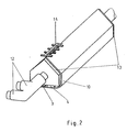
- Figure 1 shows an embodiment of the anode body and Figure 2 shows the supply lines with the end connection plates.
- the device consists essentially of a rod-shaped anode body (2) which has one or more anode edges (1).
- the objects (14) to be coated are guided along these edges (1).
- a Velcro fastener (3) and a tensioning device (4) are used to close and open the band (10) and to ensure that it is free of creases and distortion.
- the electrolyte is introduced into the anode body (2) via the feed connections (12).
- the connections (12) are located on both end connection plates (13).
- the electrolyte feed channel (5) the electrolyte reaches the connecting channels (7) via an absorbent material (11).
- the electrolyte is fed to the electrolyte carrier (6) and exits via the band (10) at the anode edge (1) to the outside.
- This anode edge (1) which is evenly moistened with electrolyte, is brought into contact with the surface areas of the electrically conductive objects (14) to be coated. A high degree of selectivity is ensured by this electrolyte, which is specifically metered at the anode edge (1).
- a heating device (9) is introduced into the electrolyte supply channels (5).
- the heater can be operated using electric heating rods or with liquid-filled heating pipes.
Landscapes
- Engineering & Computer Science (AREA)
- Chemical & Material Sciences (AREA)
- Manufacturing & Machinery (AREA)
- Chemical Kinetics & Catalysis (AREA)
- Electrochemistry (AREA)
- Materials Engineering (AREA)
- Metallurgy (AREA)
- Organic Chemistry (AREA)
- Microelectronics & Electronic Packaging (AREA)
- Electroplating Methods And Accessories (AREA)
- Coating Apparatus (AREA)
- Fixed Capacitors And Capacitor Manufacturing Machines (AREA)
Claims (7)
- Dispositif pour un revêtement galvano-plastique sélectif d'objets conducteurs électriques amenés de façon continue ou discontinue contre une anode en forme de barre, munie en section transversale d'une ou plusieurs arêtes, et par mise au contact d'un électrolyte réparti sur un support d'électrolyte, le support d'électrolyte étant en liaison avec un ruban d'une matière perméable aux liquides, absorbante et résistante à l'abrasion, qui entoure l'anode étroitement partiellement ou sur toute sa longueur, caractérisé en ce qu'un ou deux supports d'électrolyte (6) sont encastrés dans le corps d'anode (2) comme des bandes séparées, à fleur de la surface de l'anode, disposés respectivement à proximité immédiate d'une ou plusieurs arêtes d'anode (1) dans le sens longitudinal et parallèlement aux arêtes, ces supports d'électrolyte sont constitués de feutres, de tissus ou de tricots de fibres naturelles ou artificielles.
- Dispositif selon la revendication 1, caractérisé en ce que le corps d'anode (2) a une section triangulaire.
- Dispositif selon la revendication 1 ou la revendication 2, caractérisé en ce que des canaux d'alimentation d'électrolyte (5) se trouvent dans ou contre le corps d'anode (2), ils sont comblés d'une matière (11) absorbante, perméable aux liquides et ils sont en liaison le long de tout le corps d'anode (2) avec le support d'électrolyte (6) par l'intermédiaire de conduits de liaison (7).
- Dispositif selon les revendications 1 à 3, caractérisé en ce que les canaux d'alimentation en électrolyte (5) sont équipés sur les deux faces frontales du corps d'anode (2) de raccords (12) pour l'alimentation de l'électrolyte.
- Dispositif selon les revendications 1 à 4, caractérisé en ce que les canaux d'alimentation en électrolyte (5) sont munis d'un dispositif de chauffage (9).
- Dispositif selon les revendications 1 à 5, caractérisé en ce que les bandes de support d'électrolyte (6) sont placées à une distance de 1 à 20 mm de l'arête d'anode (1), mesurée à partir du bord de la bande la plus proche de l'arête.
- Dispositif selon les revendications 1 à 6, caractérisé en ce que les conduits de liaison (7) sont munis d'ajutages (8) échangeables.
Applications Claiming Priority (2)
| Application Number | Priority Date | Filing Date | Title |
|---|---|---|---|
| DE3839223A DE3839223C2 (de) | 1988-11-19 | 1988-11-19 | Vorrichtung zur selektiven galvanischen Beschichtung |
| DE3839223 | 1988-11-19 |
Publications (2)
| Publication Number | Publication Date |
|---|---|
| EP0370239A1 EP0370239A1 (fr) | 1990-05-30 |
| EP0370239B1 true EP0370239B1 (fr) | 1992-11-25 |
Family
ID=6367534
Family Applications (1)
| Application Number | Title | Priority Date | Filing Date |
|---|---|---|---|
| EP89119596A Expired - Lifetime EP0370239B1 (fr) | 1988-11-19 | 1989-10-23 | Dispositif pour l'électroplacage sélectif |
Country Status (6)
| Country | Link |
|---|---|
| US (1) | US4952296A (fr) |
| EP (1) | EP0370239B1 (fr) |
| JP (1) | JPH02185994A (fr) |
| BR (1) | BR8905799A (fr) |
| DE (2) | DE3839223C2 (fr) |
| RU (1) | RU1782251C (fr) |
Families Citing this family (9)
| Publication number | Priority date | Publication date | Assignee | Title |
|---|---|---|---|---|
| US5116480A (en) * | 1990-03-26 | 1992-05-26 | The Carolinch Company | Method and apparatus for electrolytic plating |
| CH684840A5 (fr) * | 1991-06-11 | 1995-01-13 | Electroplating Eng Eesa | Cellule pour plaquer par voie électrolytique sélectivement des zones choisies de pièces métalliques disposées en bande. |
| FR2714080B1 (fr) * | 1993-12-16 | 1996-03-01 | Dalic | Dispositif pour le traitement électrochimique, notamment localisé, d'un substrat conducteur. |
| DE4436071C2 (de) * | 1994-07-28 | 1996-09-05 | Duerrwaechter E Dr Doduco | Verfahren zum Vergolden von bandförmigem Halbzeug, insbesondere für Leadframes und nach dem Verfahren vergoldete Leadframes |
| ES2184776T3 (es) * | 1994-07-28 | 2003-04-16 | Ami Doduco Gmbh | Procedimiento para dorar semiproductos en forma de banda, especialmente para placas de circuito imprso. |
| DE19503901C2 (de) * | 1995-02-07 | 1997-01-09 | Degussa | Verfahren und Vorrichtung zum partiellen Beschichten von hohlzylindrischen Teilen |
| GB2336161B (en) * | 1998-04-06 | 2003-03-26 | John Michael Lowe | Method of providing conductive tracks on a printed circuit and apparatus for use in carrying out the method |
| SE529744C2 (sv) * | 2005-12-22 | 2007-11-13 | Abb Technology Ag | Anordning och metod för metallisk beläggning samt användning av anordningen |
| DE102020127401A1 (de) | 2020-10-16 | 2022-04-21 | Schiefer & Co., Edelmetall-Scheideanstalt (GmbH & Co.) | Apparat und Verfahren zur Aufbringung einer strukturierten Beschichtung sowie Metallgegenstand mit einer strukturierten Beschichtung |
Family Cites Families (10)
| Publication number | Priority date | Publication date | Assignee | Title |
|---|---|---|---|---|
| US4132617A (en) * | 1973-10-04 | 1979-01-02 | Galentan, A.G. | Apparatus for continuous application of strip-, ribbon- or patch-shaped coatings to a metal tape |
| US4186062A (en) * | 1978-07-13 | 1980-01-29 | Micro-Plate, Inc. | Continuous tab plater and method |
| US4425212A (en) * | 1981-11-20 | 1984-01-10 | Francis William L | Electroplating device |
| US4452684A (en) * | 1983-03-11 | 1984-06-05 | The Carolinch Company | Apparatus for selective electrolytic plating |
| US4618407A (en) * | 1984-02-09 | 1986-10-21 | Meco Equipment Engineers B.V. | Galvano-technical device for locally applying a metal layer to an elongate metal tape or the like |
| US4597845A (en) * | 1984-09-25 | 1986-07-01 | Robbins & Craig Welding & Mfg. Co. | Continuous contact plating apparatus |
| US4610772A (en) * | 1985-07-22 | 1986-09-09 | The Carolinch Company | Electrolytic plating apparatus |
| EP0222232B1 (fr) * | 1985-11-11 | 1992-01-22 | Electroplating Engineers of Japan Limited | Dispositif pour la métallisation partielle des languettes de connexion |
| DE3730740C1 (de) * | 1987-09-12 | 1988-09-29 | Degussa | Verfahren und Vorrichtung zur partiellen galvanischen Beschichtung |
| US4786389A (en) * | 1987-09-25 | 1988-11-22 | Amp Incorporated | Electroplating apparatus |
-
1988
- 1988-11-19 DE DE3839223A patent/DE3839223C2/de not_active Expired - Fee Related
-
1989
- 1989-10-23 DE DE8989119596T patent/DE58902822D1/de not_active Revoked
- 1989-10-23 EP EP89119596A patent/EP0370239B1/fr not_active Expired - Lifetime
- 1989-11-13 US US07/434,405 patent/US4952296A/en not_active Expired - Fee Related
- 1989-11-16 BR BR898905799A patent/BR8905799A/pt not_active Application Discontinuation
- 1989-11-16 RU SU894742383A patent/RU1782251C/ru active
- 1989-11-20 JP JP1299910A patent/JPH02185994A/ja active Pending
Also Published As
| Publication number | Publication date |
|---|---|
| JPH02185994A (ja) | 1990-07-20 |
| BR8905799A (pt) | 1990-06-12 |
| EP0370239A1 (fr) | 1990-05-30 |
| RU1782251C (ru) | 1992-12-15 |
| DE3839223C2 (de) | 1994-10-20 |
| DE58902822D1 (de) | 1993-01-07 |
| DE3839223C1 (fr) | 1989-12-07 |
| US4952296A (en) | 1990-08-28 |
Similar Documents
| Publication | Publication Date | Title |
|---|---|---|
| EP0370239B1 (fr) | Dispositif pour l'électroplacage sélectif | |
| EP0059787B1 (fr) | Appareil pour couvrir d'une couche mince des pièces électroconductrices composées de bandes, de rubans ou analogues pour un procédé éléctrolytrique en continu | |
| DE2052092B2 (de) | Thermodruckknopf | |
| EP0667414A1 (fr) | Dispositif de raclage | |
| DE3141036C2 (fr) | ||
| DE19735026C1 (de) | Vorrichtung zur Beschichtung einer Materialbahn mit einer Paste | |
| DE1504766B2 (de) | Verfahren und vorrichtung zum herstellen einer feinporigen kunstharzfolie | |
| EP1346424B1 (fr) | Procede pour la production d'electrodes, de composants, de demi-cellules et de cellules pour des convertisseurs d'energie electrochimiques | |
| DE1504351C3 (de) | Verfahren zum Herstellen eines aus aufeinanderliegenden Bahnen bestehenden Verbundkörpers | |
| DE957635C (de) | Verfahren und Vorrichtung zum Herstellen von Überzügen im elektrostatischen Feld, bei dem auch die Zerstäubung auf elektrostatischem Wege erfolgt | |
| DE3837835C1 (fr) | ||
| DE1816645A1 (de) | Verfahren und Vorrichtung zur selektiven galvanischen Beschichtung von endlosen Baendern aus galvanisierbarem Werkstoff | |
| DE1521306A1 (de) | Verfahren zum elektrolytischen oder chemischen Aufbringen von elektrischen Leitungszuegen | |
| DE2804801A1 (de) | Gummituchwaschvorrichtung | |
| DE2511336B2 (de) | Verfahren und einrichtung zur durchfuehrung eines behandlungs- oder herstellungsvorganges an mindestens einer der oberflaechen eines bandartigen, flexiblen traegermaterials unter verwendung einer behandlungsfluessigkeit, insbesondere zum galvanisieren | |
| EP0307611B1 (fr) | Procédé et dispositif pour le dépôt électrolytique sur les surfaces déterminées | |
| DE2316176C3 (de) | Verfahren zur Herstellung mehrlagiger Leiterbahnenstrukturen auf einem Substrat mittels eines programmgesteuerten, für die Leiterbahnenherstellung herangezogenen Werkzeuges | |
| EP0859071B1 (fr) | Procédé de revêtement sélectif galvanique d'éléments de contact électrique | |
| DE2032398A1 (de) | Einrichtung zum Bearbeiten von flachenfbrmigem Material | |
| JPH0125391B2 (fr) | ||
| DE2110491B2 (de) | Vorrichtung zum stellenweisen auftragen von selbstklebeklebstoff | |
| DE2002517A1 (de) | Vorrichtung zum Aufbringen einer fluessigen Oberflaechenschicht auf eine Platte od.dgl. | |
| DE586490C (de) | Verfahren und Vorrichtung zur elektrolytischen Herstellung von metallischen Baendern | |
| DE10008996A1 (de) | Herstellungsverfahren für Längenmessvorrichtungen in Strang- oder Bandform | |
| DE1064375B (de) | Verfahren zur Herstellung eines Schleifwerkzeugs mit unterbrochenem Schleifbelag |
Legal Events
| Date | Code | Title | Description |
|---|---|---|---|
| PUAI | Public reference made under article 153(3) epc to a published international application that has entered the european phase |
Free format text: ORIGINAL CODE: 0009012 |
|
| 17P | Request for examination filed |
Effective date: 19891023 |
|
| AK | Designated contracting states |
Kind code of ref document: A1 Designated state(s): BE DE FR GB IT NL |
|
| 17Q | First examination report despatched |
Effective date: 19910729 |
|
| GRAA | (expected) grant |
Free format text: ORIGINAL CODE: 0009210 |
|
| AK | Designated contracting states |
Kind code of ref document: B1 Designated state(s): BE DE FR GB IT NL |
|
| ITF | It: translation for a ep patent filed | ||
| ET | Fr: translation filed | ||
| REF | Corresponds to: |
Ref document number: 58902822 Country of ref document: DE Date of ref document: 19930107 |
|
| GBT | Gb: translation of ep patent filed (gb section 77(6)(a)/1977) |
Effective date: 19930302 |
|
| PLBI | Opposition filed |
Free format text: ORIGINAL CODE: 0009260 |
|
| PGFP | Annual fee paid to national office [announced via postgrant information from national office to epo] |
Ref country code: DE Payment date: 19930921 Year of fee payment: 5 |
|
| 26 | Opposition filed |
Opponent name: DODUCO GMBH & CO. DR.EUGEN DUERRWAECHTER Effective date: 19930825 |
|
| PG25 | Lapsed in a contracting state [announced via postgrant information from national office to epo] |
Ref country code: GB Effective date: 19931023 |
|
| PG25 | Lapsed in a contracting state [announced via postgrant information from national office to epo] |
Ref country code: BE Effective date: 19931031 |
|
| NLR1 | Nl: opposition has been filed with the epo |
Opponent name: DODUCO GMBH & CO. DR.EUGEN DUERRWAECHTER |
|
| BERE | Be: lapsed |
Owner name: DEGUSSA A.G. Effective date: 19931031 |
|
| RDAC | Information related to revocation of patent modified |
Free format text: ORIGINAL CODE: 0009299REVO |
|
| RDAG | Patent revoked |
Free format text: ORIGINAL CODE: 0009271 |
|
| STAA | Information on the status of an ep patent application or granted ep patent |
Free format text: STATUS: PATENT REVOKED |
|
| NLV4 | Nl: lapsed or anulled due to non-payment of the annual fee | ||
| GBPC | Gb: european patent ceased through non-payment of renewal fee |
Effective date: 19931023 |
|
| 27W | Patent revoked |
Effective date: 19940311 |
|
| REG | Reference to a national code |
Ref country code: FR Ref legal event code: ST |
|
| R27W | Patent revoked (corrected) |
Effective date: 19940311 |