EP0370002B1 - Apparatus for wrapping demagnetizing coils with insulating tape - Google Patents
Apparatus for wrapping demagnetizing coils with insulating tape Download PDFInfo
- Publication number
- EP0370002B1 EP0370002B1 EP88900472A EP88900472A EP0370002B1 EP 0370002 B1 EP0370002 B1 EP 0370002B1 EP 88900472 A EP88900472 A EP 88900472A EP 88900472 A EP88900472 A EP 88900472A EP 0370002 B1 EP0370002 B1 EP 0370002B1
- Authority
- EP
- European Patent Office
- Prior art keywords
- drum
- tape
- hank
- edge
- pincer
- Prior art date
- Legal status (The legal status is an assumption and is not a legal conclusion. Google has not performed a legal analysis and makes no representation as to the accuracy of the status listed.)
- Expired - Lifetime
Links
- 210000000080 chela (arthropods) Anatomy 0.000 claims abstract description 27
- 238000007493 shaping process Methods 0.000 claims abstract description 8
- 239000000463 material Substances 0.000 claims abstract 2
- 238000003466 welding Methods 0.000 claims description 13
- 238000013459 approach Methods 0.000 claims description 9
- 230000009471 action Effects 0.000 claims description 5
- 230000007246 mechanism Effects 0.000 claims description 3
- 230000000694 effects Effects 0.000 claims description 2
- 230000015572 biosynthetic process Effects 0.000 claims 2
- 230000005540 biological transmission Effects 0.000 description 7
- 238000010586 diagram Methods 0.000 description 6
- 238000000034 method Methods 0.000 description 3
- 238000004026 adhesive bonding Methods 0.000 description 2
- 238000001816 cooling Methods 0.000 description 2
- 230000008569 process Effects 0.000 description 2
- 238000007664 blowing Methods 0.000 description 1
- 230000006835 compression Effects 0.000 description 1
- 238000007906 compression Methods 0.000 description 1
- 230000000881 depressing effect Effects 0.000 description 1
- 230000009977 dual effect Effects 0.000 description 1
- 238000001125 extrusion Methods 0.000 description 1
- 238000009413 insulation Methods 0.000 description 1
- 230000001788 irregular Effects 0.000 description 1
- 230000002459 sustained effect Effects 0.000 description 1
- 238000004804 winding Methods 0.000 description 1
Images



Classifications
-
- H—ELECTRICITY
- H01—ELECTRIC ELEMENTS
- H01F—MAGNETS; INDUCTANCES; TRANSFORMERS; SELECTION OF MATERIALS FOR THEIR MAGNETIC PROPERTIES
- H01F41/00—Apparatus or processes specially adapted for manufacturing or assembling magnets, inductances or transformers; Apparatus or processes specially adapted for manufacturing materials characterised by their magnetic properties
- H01F41/02—Apparatus or processes specially adapted for manufacturing or assembling magnets, inductances or transformers; Apparatus or processes specially adapted for manufacturing materials characterised by their magnetic properties for manufacturing cores, coils, or magnets
- H01F41/04—Apparatus or processes specially adapted for manufacturing or assembling magnets, inductances or transformers; Apparatus or processes specially adapted for manufacturing materials characterised by their magnetic properties for manufacturing cores, coils, or magnets for manufacturing coils
- H01F41/12—Insulating of windings
- H01F41/125—Other insulating structures; Insulating between coil and core, between different winding sections, around the coil
Definitions
- Ordinary demagnetizing coils are known to consist of a continuous hank of electric wire covered with a plastic sheath obtained by winding a tape spirally around said hank.
- the sheath so created is discontinuous, irregular and does not give satisfactory insulation.
- the reference patent DE-A2602 116 teaches sheathing of a coil by using a shaped tape formed by a process of extrusion.
- Said tape is placed in an annular die thus forming a kind of channel in which the coil is then laid.
- Shaping rollers press the tape against the coil and thus press the edges of said tape one against the other determining superimposition of their internal face.
- Said edges are closed by glueing, welding or pressure.
- glueing welding or pressure.
- the specially extruded tape is a good deal more expensive than one of the ordinary flat tapes on the market.
- the snap closure is bulky and insufficiently secure.
- edges are united by welding or glueing, in order to achieve continuity the overlapping edges must project considerably over the outer surface of the sheath forming an external longitudinal rib both bulky and of a poor appearance.
- Subject of the invention is an apparatus for automatically producing demagnetizing coils comprising a hank of electric wire and a plastic sheath.
- the sheath is made from an ordinary flat tape made to curve channelwise gradually along its length by means of a shaping guide, and is laid in the circumferential groove of a rotating drum.
- the drum consists of two disks, one fixed to a drive shaft and the other being free to detach itself from the first, translating away by means of a mechanism but drawn along by rotation of the shaft. In this way the demagnetizing coil can be discharged and allowed to pass between the two disks.
- One end of a pin is attached, but rotatable, near the edge of the disk fixed to the shaft while the other end, having passed through the translatable disk, supports a perpendicularly set arm placed in contact with a cam held to the outer side of the latter disk, by means of a spring.
- a spike is mounted on the pin, at the point where there is a recess in the groove of the drum, said spike being bent in the direction opposite to that of the movement and inclined towards the inside of said groove to allow the tape to be hooked on.
- the drum is opened, namely the translating disk moves away from the fixed disk and, as a consequence, the cam,acting on the arm, determines rotation of the pin and therefore inclination of the spike towards the outside of the drum, allowing the coil to become detached.
- a pincer gradually curves the longitudinal edges of the tape laying them over the hank.
- Each of the pincer's two jaws has at its end an articulated arm held in place by a spring and by a limit stop inside the pincer.
- a head Inside said arm a head is fixed, said head containing a groove shaped similarly to the arc of a circle open to approximately 90°.
- the end of said arc,innermost towards the pincer's articulation, is substantially at 90° to the side of the arm.
- the second jaw then moves and lays the inner surface of the other edge of the tape over the outer surface of the first one.
- a device placed immediately beyond the pincer, comprising a roller to press down the edges of the tape together with a blowpipe for emission of hot air and a blowpipe for cooling air, welds the two edges of the tape by simultaneous application of pressure and heat.
- This sequence is operated and checked by an electronic unit comprising a programmer, together with various devices for control and information.
- a number of sensors cause the second jaw of the pincer to operate after the first jaw has completed curving of the first edge of the tape; bring the pressure roller up to the drum when the second jaw has completed curving the second edge of the tape; cause the welding blowpipe to function after the pressure roller has completed its stroke; open the drum to discharge the demagnetizing coil when said coil is complete.
- the invention described offers considerable advantages.
- the cost of the sheath is much lower as one of the flat tapes already on the market is used and not one specifically extruded.
- the sheath ensures close adherence to the coil without any projections, ribs or roughness, bult being reduced to a minimum and appearance appreciably improved.
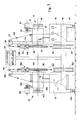
- the complex (10) comprises the two substantially similar machines (11), (12), the control unit (13), the pneumatic unit (14), the electric-electronic unit (15) and the base (16).
- Each machine can operate independently of the other so that one sequence of functions can proceed while the other machine is being prepared for the next sequence.
- the machine (11) comprises the framework (17), the drum (20) drawn along by the shaft (30), the step-by-step electric motor (31), the transmission (32), the reel (46)for feeding in the tape (24), the pincers (23) for shaping the sheath (24'')(Fig.13),the electric wire (27) container (87), the programmer (28) fixing the number of turns for each coil, the button switch (34) for starting up the machine.
- the reel (46) is served by the brake consisting of the roller (40) fixed to the reel, the block (41) articulating on the pin (42) in said lever (43) pivoting at (44) and loaded by the traction spring (45).
- the tape (24),through the transmission wheels (48) (48') and (49),(49') and the shaping guide (35), can be hooked to the drum (20).
- the drum is made up of the disk (21) mounted on the shaft (30) (see also Figs. 3 and 4) and of the disk (22) caused to rotate with said shaft but free to translate pushed by the bushing (50) fixed to the sleeve (51).
- Said sleeve is worked by the fork (52) fixed to the lever (53) rotating on the pin (54) of support (55). At the other end of the lever the pin (56) connects it to the piston(57) of the pneumatic cylinder (58) worked by the handle (33) see (Fig.1).
- the smaller shaft (61) is mounted on the disk (21) by a screw (60), said shaft passing through the disk (22) and emerging near to the cam (62) is fixed in position by screws (63), (64).
- the perpendicular arm (65) is mounted on a shaft (61) and is connected to the pin (66) on a disk (22) by a traction spring (67).
- the spike (68) thus becomes inclined towards the drum (Fig.4) and so can hook onto the tape when the cycle starts.
- Cog wheel (76) is mounted on the shaft (79) carrying the step-by-step motor (31).
- the cogged belts (77) and (78) respectively connect the pairs of cog wheels (73), (74) and (75), (76).
- the electronic control device (86) is connected to the electronic unit (15),comprising disks (80), (81) notched at (82) and (83) in order so to create pulses on the photoelectric cells (84), (85).
- the pin (108) is mounted on lever (100) carrying the roller (109).
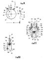
- Notch (96) is cut into the edge of disk (21) of the drum (20), said notch allowing passage at the end of the electric wire (27) and hook-up to spring (97) mounted inside a hole (98) in disk (21) (see also Fig.10).
- the pincers (23) are placed, with jaws (110), (111) articulating on pin (112) (see also Fig.11), comprising arms (113), (114) with rounded ends (125), (126) said arms articulating in pins (115), (116), respectively supporting head (117) with its groove (118) and head (119) with its groove (120).
- the upper ends, respectively (118') and (120') of said grooves are at about 90° in relation to the sides of the arms.
- the heads are respectively pulled by the traction springs (121), (122) against the ends of the end-stroke screws (123), (124) adjusting the position of said heads.
- the jaws are worked respectively by the pneumatic cylinders (130), (131) suspended to rods (132), (133).
- the pressure roller (145) is placed immediately beyond the blowpipe, said roller being supported by the angular lever (146) pivoting at (147) and operated by the pneumatic cylinder (148).
- the shaping guide (35), (Fig.5) comprises an initial flat part (35') with the edges (36), (37) bent back so as to create a rectangular fissure and a final part (35'') approximately V-shaped.
- the machine (12) shows the main features corresponding to those of machine(11) such as the frame (150), the drum (151), the shaft (152), the step-by-step electric motor (153), the transmission (154), the handle (155), the reel (156) supplying tape (157), the pincers (158), the feeder (159) of electric wire (160), the numberer (161), and the starting button switch (162).
- the drum (20), (Figs. 3, 4) is closed by acting on lever (33), (Fig.1.).
- the electric wire (27) is hooked to spring (97) an disk(21) making said wire pass through the transmission roller (109) and the notch (96) in said disk (Figs. 2, 9,10).
- Drum (20) is rotated until a length of tape (24') is completely wound on it and slighly overlies the end already hooked to the spike (68) and an initial turn of electric wire is completed round the tape.
- Said tape (24') is then cut by hand close to the drum and the guide (35) is overturned to allow the tape (24) to remain over the transmission roller (49') (Fig.9).
- a start is made with forming the coil (27') by depressing push button (34)(Fig.1) having previously set the number of turns to be made on the counter (28).
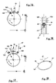
- control device (86) sends a signal to the electronic unit (15) which gradually slows down and stops the motor (31) at an exact point with automatic closure of the pincer jaws (23) (Figs.11,12,13).
- Jaw (110) is the first to approach the edge (25) of the tape (24).
- An electronic sensor sets off the second jaw (111) which, with the same mechanisms as before, by means of groove (120) in head (119), causes the edge (26) of tape (24') to curve round the hank (27) and "on top” of the edge (25).
- the welding device and pincers then automatically move away from the drum and the machine stops.
- Hand scissors (59) are used to cut the electric wire (27) (Fig.17), the drum is opened by lever (33) (Fig.1) and the coil (29) complete with sheath (Fig.18) can be extracted by making it pass between disks (20), (21).
Landscapes
- Engineering & Computer Science (AREA)
- Power Engineering (AREA)
- Manufacturing & Machinery (AREA)
- Basic Packing Technique (AREA)
- Processes Specially Adapted For Manufacturing Cables (AREA)
- Decoration Of Textiles (AREA)
- Manufacture Of Motors, Generators (AREA)
Applications Claiming Priority (2)
| Application Number | Priority Date | Filing Date | Title |
|---|---|---|---|
| IT2183187 | 1987-09-08 | ||
| IT8721831A IT1226073B (it) | 1987-09-08 | 1987-09-08 | Apparecchio per la formazione automatica della guaina nelle bobine di smagnetizzazione partendo da un nastro piatto, mediante la saldatura della faccia interna d'un lembo longitudinale con quella esterna del secondo lembo. |
Publications (2)
| Publication Number | Publication Date |
|---|---|
| EP0370002A1 EP0370002A1 (en) | 1990-05-30 |
| EP0370002B1 true EP0370002B1 (en) | 1993-03-31 |
Family
ID=11187476
Family Applications (1)
| Application Number | Title | Priority Date | Filing Date |
|---|---|---|---|
| EP88900472A Expired - Lifetime EP0370002B1 (en) | 1987-09-08 | 1987-12-17 | Apparatus for wrapping demagnetizing coils with insulating tape |
Country Status (6)
| Country | Link |
|---|---|
| EP (1) | EP0370002B1 (it) |
| AU (1) | AU1053788A (it) |
| DE (1) | DE3785218T2 (it) |
| ES (1) | ES2008402A6 (it) |
| IT (1) | IT1226073B (it) |
| WO (1) | WO1989002649A1 (it) |
Families Citing this family (1)
| Publication number | Priority date | Publication date | Assignee | Title |
|---|---|---|---|---|
| CN113493144B (zh) * | 2021-07-22 | 2022-11-18 | 淮南文峰光电科技股份有限公司 | 一种制造电缆用的自动化缠绕设备 |
Family Cites Families (6)
| Publication number | Priority date | Publication date | Assignee | Title |
|---|---|---|---|---|
| DE875688C (de) * | 1948-10-02 | 1953-05-04 | Siemens Ag | Einlagige spulenfoermige Wicklung fuer elektrische Geraete und Maschinen und Verfahren zum Isolieren solcher Wicklungen |
| DE956255C (de) * | 1952-08-17 | 1957-01-17 | Siemens Ag | Aus Kunststoffolie bestehende, allseitig geschlossene Umhuellung eines Ringkoerpers, insbesondere Isolierhuelle einer elektrischen Spule, beispielsweise einer Zaehlerspannungsspule |
| FR1218429A (fr) * | 1957-04-05 | 1960-05-10 | Lucas Industries Ltd | Perfectionnements aux bobines électriques |
| DE2602116C3 (de) * | 1976-01-21 | 1980-01-24 | Ute 6122 Erbach Breimer Geb. Roth | Vorrichtung zum Umhüllen einer Ringspule mit einem Isolierwerkstoff |
| DE2755840C2 (de) * | 1977-12-15 | 1981-10-08 | geb. Roth Ute 6120 Erbach Breimer | Vorrichtung zum Umhüllen einer Ringspule mit einem Isolierwerkstoff |
| GB2033297B (en) * | 1978-11-08 | 1982-09-08 | Lalor W T | Composite tapes and apparatus for winding composite tapes |
-
1987
- 1987-09-08 IT IT8721831A patent/IT1226073B/it active
- 1987-12-17 AU AU10537/88A patent/AU1053788A/en not_active Abandoned
- 1987-12-17 DE DE88900472T patent/DE3785218T2/de not_active Expired - Lifetime
- 1987-12-17 WO PCT/IT1987/000102 patent/WO1989002649A1/en not_active Ceased
- 1987-12-17 EP EP88900472A patent/EP0370002B1/en not_active Expired - Lifetime
- 1987-12-30 ES ES8703752A patent/ES2008402A6/es not_active Expired
Also Published As
| Publication number | Publication date |
|---|---|
| AU1053788A (en) | 1989-04-17 |
| DE3785218T2 (de) | 1993-10-07 |
| IT8721831A0 (it) | 1987-09-08 |
| ES2008402A6 (es) | 1989-07-16 |
| EP0370002A1 (en) | 1990-05-30 |
| WO1989002649A1 (en) | 1989-03-23 |
| IT1226073B (it) | 1990-12-10 |
| DE3785218D1 (de) | 1993-05-06 |
Similar Documents
| Publication | Publication Date | Title |
|---|---|---|
| JPS5842445A (ja) | ゴムシ−ト貼付け装置 | |
| CA2127180C (en) | Automatic roll wrapper removing apparatus and method | |
| US5328533A (en) | Bead apex applying method and device | |
| JP2714959B2 (ja) | 粘着性リボン状材料の自動巻付け方法及び装置 | |
| EP0370002B1 (en) | Apparatus for wrapping demagnetizing coils with insulating tape | |
| US4765553A (en) | Winding apparatus | |
| US4759813A (en) | Process for forming and crimping a bead | |
| EP0719633B1 (en) | Method and apparatus for preparing strip material | |
| US4806196A (en) | Bead crimping and handling system | |
| JPS6230096B2 (it) | ||
| JPH08156908A (ja) | フィルムシート梱包機 | |
| JPS6116611B2 (it) | ||
| CN214673395U (zh) | 一种自融性胶带配合电缆熔接头制作的包带装置 | |
| JP2539242B2 (ja) | スチ―ルコ―ド入り帯状部材の接合装置 | |
| JPH051733B2 (it) | ||
| JPS6010929B2 (ja) | 鋼板コイル包装用紙供給装置 | |
| JPH026759Y2 (it) | ||
| JPH08282610A (ja) | 円筒体表面へのカット紙巻着装置およびこれを用いた紙巻き装置並びに該装置による紙巻き方法 | |
| JP2922775B2 (ja) | 汎用結束機 | |
| JPH0547389B2 (it) | ||
| JPS5926526B2 (ja) | 包装機の張力調整装置 | |
| JPH0520520Y2 (it) | ||
| CA2383430C (en) | Method and apparatus for making a knot with flexible material wrapped around an article | |
| JPH0156188B2 (it) | ||
| JPS6110982Y2 (it) |
Legal Events
| Date | Code | Title | Description |
|---|---|---|---|
| PUAI | Public reference made under article 153(3) epc to a published international application that has entered the european phase |
Free format text: ORIGINAL CODE: 0009012 |
|
| 17P | Request for examination filed |
Effective date: 19900228 |
|
| AK | Designated contracting states |
Kind code of ref document: A1 Designated state(s): DE FR GB NL |
|
| 17Q | First examination report despatched |
Effective date: 19920518 |
|
| GRAA | (expected) grant |
Free format text: ORIGINAL CODE: 0009210 |
|
| AK | Designated contracting states |
Kind code of ref document: B1 Designated state(s): DE FR GB NL |
|
| REF | Corresponds to: |
Ref document number: 3785218 Country of ref document: DE Date of ref document: 19930506 |
|
| ET | Fr: translation filed | ||
| PLBE | No opposition filed within time limit |
Free format text: ORIGINAL CODE: 0009261 |
|
| STAA | Information on the status of an ep patent application or granted ep patent |
Free format text: STATUS: NO OPPOSITION FILED WITHIN TIME LIMIT |
|
| 26N | No opposition filed | ||
| PGFP | Annual fee paid to national office [announced via postgrant information from national office to epo] |
Ref country code: GB Payment date: 19951211 Year of fee payment: 9 |
|
| PGFP | Annual fee paid to national office [announced via postgrant information from national office to epo] |
Ref country code: NL Payment date: 19951230 Year of fee payment: 9 |
|
| PGFP | Annual fee paid to national office [announced via postgrant information from national office to epo] |
Ref country code: DE Payment date: 19960125 Year of fee payment: 9 |
|
| PG25 | Lapsed in a contracting state [announced via postgrant information from national office to epo] |
Ref country code: GB Effective date: 19961217 |
|
| PG25 | Lapsed in a contracting state [announced via postgrant information from national office to epo] |
Ref country code: NL Effective date: 19970701 |
|
| GBPC | Gb: european patent ceased through non-payment of renewal fee |
Effective date: 19961217 |
|
| NLV4 | Nl: lapsed or anulled due to non-payment of the annual fee |
Effective date: 19970701 |
|
| PG25 | Lapsed in a contracting state [announced via postgrant information from national office to epo] |
Ref country code: DE Effective date: 19970902 |
|
| PGFP | Annual fee paid to national office [announced via postgrant information from national office to epo] |
Ref country code: FR Payment date: 20041124 Year of fee payment: 18 |
|
| PG25 | Lapsed in a contracting state [announced via postgrant information from national office to epo] |
Ref country code: FR Free format text: LAPSE BECAUSE OF NON-PAYMENT OF DUE FEES Effective date: 20060831 |
|
| REG | Reference to a national code |
Ref country code: FR Ref legal event code: ST Effective date: 20060831 |