US4759813A - Process for forming and crimping a bead - Google Patents
Process for forming and crimping a bead Download PDFInfo
- Publication number
- US4759813A US4759813A US07/026,600 US2660087A US4759813A US 4759813 A US4759813 A US 4759813A US 2660087 A US2660087 A US 2660087A US 4759813 A US4759813 A US 4759813A
- Authority
- US
- United States
- Prior art keywords
- bead
- former
- ribbon
- leading end
- roller
- Prior art date
- Legal status (The legal status is an assumption and is not a legal conclusion. Google has not performed a legal analysis and makes no representation as to the accuracy of the status listed.)
- Expired - Lifetime
Links
Images


Classifications
-
- B—PERFORMING OPERATIONS; TRANSPORTING
- B29—WORKING OF PLASTICS; WORKING OF SUBSTANCES IN A PLASTIC STATE IN GENERAL
- B29D—PRODUCING PARTICULAR ARTICLES FROM PLASTICS OR FROM SUBSTANCES IN A PLASTIC STATE
- B29D30/00—Producing pneumatic or solid tyres or parts thereof
- B29D30/06—Pneumatic tyres or parts thereof (e.g. produced by casting, moulding, compression moulding, injection moulding, centrifugal casting)
- B29D30/48—Bead-rings or bead-cores; Treatment thereof prior to building the tyre
-
- D—TEXTILES; PAPER
- D07—ROPES; CABLES OTHER THAN ELECTRIC
- D07B—ROPES OR CABLES IN GENERAL
- D07B7/00—Details of, or auxiliary devices incorporated in, rope- or cable-making machines; Auxiliary apparatus associated with such machines
- D07B7/16—Auxiliary apparatus
- D07B7/165—Auxiliary apparatus for making slings
-
- D—TEXTILES; PAPER
- D07—ROPES; CABLES OTHER THAN ELECTRIC
- D07B—ROPES OR CABLES IN GENERAL
- D07B7/00—Details of, or auxiliary devices incorporated in, rope- or cable-making machines; Auxiliary apparatus associated with such machines
- D07B7/16—Auxiliary apparatus
- D07B7/167—Auxiliary apparatus for joining rope components
-
- B—PERFORMING OPERATIONS; TRANSPORTING
- B29—WORKING OF PLASTICS; WORKING OF SUBSTANCES IN A PLASTIC STATE IN GENERAL
- B29D—PRODUCING PARTICULAR ARTICLES FROM PLASTICS OR FROM SUBSTANCES IN A PLASTIC STATE
- B29D30/00—Producing pneumatic or solid tyres or parts thereof
- B29D30/06—Pneumatic tyres or parts thereof (e.g. produced by casting, moulding, compression moulding, injection moulding, centrifugal casting)
- B29D30/48—Bead-rings or bead-cores; Treatment thereof prior to building the tyre
- B29D2030/485—Bead-rings or bead-cores; Treatment thereof prior to building the tyre the bead cores being made using a band containing a plurality of wires embedded in rubber
-
- B—PERFORMING OPERATIONS; TRANSPORTING
- B29—WORKING OF PLASTICS; WORKING OF SUBSTANCES IN A PLASTIC STATE IN GENERAL
- B29D—PRODUCING PARTICULAR ARTICLES FROM PLASTICS OR FROM SUBSTANCES IN A PLASTIC STATE
- B29D30/00—Producing pneumatic or solid tyres or parts thereof
- B29D30/06—Pneumatic tyres or parts thereof (e.g. produced by casting, moulding, compression moulding, injection moulding, centrifugal casting)
- B29D30/48—Bead-rings or bead-cores; Treatment thereof prior to building the tyre
- B29D2030/487—Forming devices for manufacturing the beads
-
- D—TEXTILES; PAPER
- D07—ROPES; CABLES OTHER THAN ELECTRIC
- D07B—ROPES OR CABLES IN GENERAL
- D07B2501/00—Application field
- D07B2501/20—Application field related to ropes or cables
- D07B2501/2046—Tire cords
- D07B2501/2053—Tire cords for wheel rim attachment
Definitions
- the bead, along with other beads, formed at the same time may then be removed from the former by an end effector having unloading fingers with belts for accumulating beads while maintaining the spacing thereof.
- the present invention is directed to a method and apparatus for crimping the bead while it is still on the former to avoid the additional handling of the formed bead.
- One of the problems associated with bead formers has been the gripping of the leading end of the bead ribbon which has resulted in the leading end protruding from the inside of the formed bead. It has been proposed to use a gripper which swings radially outward pressing the leading end against a segment of the former. This may reduce the bending and avoid a permanent set in the leading end of the bead ribbon; however, the leading end is still unsupported and still protrudes from the inside of the bead and therefore the bead must be removed from the former to crimp or wrap the bead splice area.
- the leading end of the bead ribbon is gripped during the initial winding of the bead ribbon and then released and pressed radially outward into a supported position against the inner surface of the bead so that the bead splice can be crimped on the bead former.
- the pressing roller is mounted in a guide cage having guiding ribs for positioning a plurality of bead ribbons on the former.
- a dual arm system supports the guide cage and pressing roller and has dual actuating cylinders for selectively guiding the bead ribbons and pressing the beads with the desired pressures for initially compacting the ribbons and finally crimping the beads. With this system the crimping can be done without rotating the former by stroking the pressing roller along the surface of the former.
- the beads can be removed from the former and accumulated on the belts while at the same time maintaining the spacing of the beads.
- a bead forming and crimping apparatus comprising a rotatable cylindrical former for winding a bead ribbon in a plurality of convolutions to form the bead, the former having a gripping mechanism for gripping a leading end of the bead ribbon at a recessed position below the surface of the former, means to rotate the former an initial amount to wrap the bead ribbon around the former a predetermined number of revolutions, roller means to press the outer surface of the bead ribbon as the former is rotated to compact the convolutions of the bead ribbon laid on the former, the gripping mechanism including means for releasing the leading end and means for moving the leading end radially outward to a support position at the surface of the former, means to rotate the former a latter amount to wrap the bead ribbon around the former a predetermined number of additional revolutions until a trailing end of the bead ribbon is pressed against the bead, means for applying pressure to compact the convolutions of the be
- a system for crimping and handling tire beads comprising means for wrapping a plurality of bead ribbons around a generally cylindrical former at predetermined spaced-apart positions to form a plurality of beads at the predetermined spaced-apart positions, means for crimping the beads, means to insert a plurality of unloading fingers into position inside the beads and in engagement with the inner periphery of each of the beads without changing the predetermined spaced-apart positions and means for releasing the beads from the cylindrical former to permit removal of the unloading fingers and the beads from the cylindrical former.
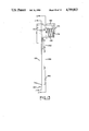
- FIG. 1 is a front elevation of a bead forming and crimping apparatus embodying the invention showing the former schematically in dot-dash lines.
- FIG. 2 is a side elevation taken along line 2--2 in FIG. 1 with parts being broken away.
- FIG. 3 is an enlarged sectional view of the guide cage taken along line 3--3 in FIG. 1.
- FIG. 4 is an enlarged front elevation of the bead former in the expanded position showing the gripper arm and gripper seat member in the gripping position with parts being broken away.
- FIG. 5 is an enlarged front elevation of the bead former shown in FIG. 4 in the disengaged condition with the gripper seat member expanded to support a leading end of the bead ribbon and with the unloading fingers shown in section taken along line 5--5 in FIG. 8.
- FIG. 6 is a sectional view taken along line 6--6 in FIG. 5 but showing the former in the retracted position.
- FIG. 7 is an enlarged fragmentary sectional view taken along line 7--7 in FIG. 5.
- FIG. 8 is a side elevation of the finger mount assembly shown mounted on a robot arm and with the unloading fingers in position for insertion into the former shown in FIG. 5, the angle of the upper unloading finger being tilted to show a side perspective.
- FIG. 9 is a front elevation of the finger mount assembly with the unloading fingers removed.
- FIG. 10 is an enlarged side elevation of one of the unloading fingers shown in FIG. 8.
- FIG. 11 is a sectional view taken along line 11--11 in FIG. 13.
- FIG. 12 is a sectional view taken along line 12--12 in FIG. 13.
- FIG. l3 is a plan view taken along line 13--13 in FIG. 10.
- FIG. 14 is a sectional view taken along line 14--14 in FIG. 10.
- FIG. 15 is a sectional view taken along line 15--15 in FIG. 10.
- a bead forming and crimping apparatus 10 is shown in which a plurality of bead ribbons 12 are wrapped around a former 14 to form a plurality of beads 16, as shown in FIGS. 5 and 6.
- the bead ribbons 12 have strands of high strength, relatively nonextensible material, such as wire coated with an insulating material which may be of rubber. As the bead ribbons 12 are wrapped around the former 14 they are pressed against an outer surface 18 of the former 14 by a roller 20.
- the roller 20 is carried by a pressing arm means including a pivot arm member 22 mounted on a shaft 24 rotatably supported by bearings 26 in bushing 28 mounted on an upright supporting member 30 connected to a supporting structure such as bracket 32.
- a first pressure means such as first pneumatic cylinder 34 is mounted on the bracket 32 and has a piston rod 36 connected to a lower end 38 of the pivot arm member 22.
- a movement-limiting rod 40 is connected to the lower end 38 of the pivot arm member 22 and extends through an opening in a stop plate 42 mounted on the first pneumatic cylinder 34.
- Adjustable stops 44 and 46 are mounted on the rod 40 at predetermined positions for controlling the swinging movement of the pivot arm 22 about an axis A--A of the shaft 24.
- Crimp arm member 48 is rotatably mounted on an upper end 50 of the pivot arm member 22 and has a roller supporting portion 52 on which a guide cage 54 is mounted. As shown in FIG. 3, the roller 20 is rotatably mounted in the guide cage 54 on bearings 56. Guide members such as ribs 57 at spaced-apart positions on the guide cage 54 are provided to engage side edges of the bead ribbons 12 and guide the bead ribbons into spaced positions on the outer surface 18 of the former 14.
- An actuating portion 58 of the crimp arm member 48 extends away from the pivotal connection to the pivot arm member 22 in a direction opposite to the roller supporting portion 52 and is connected to a second pressure means such as a second pneumatic cylinder 60 mounted on the pivot arm member and connected to the actuating portion 58 by a piston rod 62.
- a control rod 64 is connected to the actuating portion 58 and extends through a stop plate 66 mounted on the second pneumatic cylinder 60. Stops 68 and 70 are adjustably mounted on the control rod 64 for limiting the movement of the piston rod 62 and therefore the swinging movement of the crimping arm member 48.
- the former 14 is of the expandable type with a chuck having three segments 72 hingedly connected to a pivot plate 74 by pivot links 76.
- the pivot plate 74 is mounted on linear shafts 78 in linear bearings 80 mounted on a front flange 82 of the former 14.
- the linear shafts 78 are connected to a shaft flange 84 which is connected to a piston rod 86 of a double-acting pneumatic cylinder 88 mounted on the front flange 82 for moving the shaft flange toward and away from the front flange so that the linear shaft 78 will move the pivot plate 74 toward and away from the front flange causing the segments 72 to be moved between the retracted position shown in FIG. 6 and an expanded position shown in FIG. 4.
- a gripping and supporting mechanism including a gripper arm 90 rotatably mounted about a first axis B--B and a swingable gripper seat member 92 rotatably mounted about a second axis C--C.
- the gripper arm 90 has a gripping surface 94 at one end and is connected to a pneumatic double-acting piston and cylinder assembly 96 at the other end for swinging the arm from a gripping position, shown in FIG. 4, to a release position, shown in FIG. 5.
- the gripper seat member 92 is engageable with a spring 98 for rotating the gripper seat member 92 from a support position, shown in FIG. 5, to a gripping position, shown in FIG. 4.
- a stop surface 100 at one end of the gripper seat member 92 is engageable with a flange 102 of the segment 72.
- the flange 102 has an opening 104 through which the bead ribbons 12 can be fed over the gripper seat member 92 into the position shown in FIG. 4 where the gripper arm 90 may be rotated by the piston and cylinder assembly 96 for urging the gripping surface 94 against a leading end 106 of each of the bead ribbons 12 as shown in FIG. 4.
- the leading end 106 is gripped while the former 14 is expanded to the position shown in FIG. 4.
- the front flange 82 is connected to a cylindrical supporting member 108 for mounting on a spindle 110 having a key 112 engageable with a keyway 114 in the cylindrical supporting member 108.
- the spindle 110 may be connected to a suitable power means for rotating the former 14 and controlled by suitable control means for stopping the former at a desired position.
- a rotary air joint including a housing 116 may be provided around the cylindrical supporting member 108 for communicating air under pressure to the cylinder 88 for expanding and contracting the segment 72 and to double-acting piston and cylinder assembly 96 for rotating the gripper arm 90.
- the former 14 is rotated in the counterclockwise direction, as shown in FIG. 4, for a predetermined number of revolutions and the second pneumatic cylinder 60 is actuated at a low pressure of about 20 psi (1.4 kg/cm 2 ) to rotate the crimp arm member 48 and urge roller 20 into engagement with the ribbons 12.
- This compacts the convolutions of bead ribbons 12 laid on the flange 102 of the segments 72 partially forming the beads 16.
- the former 14 is rotated three times.
- the piston and cylinder assembly 96 is actuated to rotate the gripper arm 90 in a counterclockwise direction pulling the gripping surface 94 away from the leading end 106 of each of the ribbons 12.
- the roller cam connection between the gripper arm 90 and the gripper seat member 92 then causes the gripper seat member to rotate in a clockwise direction tion about the axis C--C into the position shown in FIG. 5.
- the roller cam connection includes a cam surface 118 engageable with a roller follower 120 mounted on a follower arm attached to the gripper arm 90. When the gripper arm 90 is rotated in a counterclockwise direction, the roller follower 120 is moved into engagement the cam surface 118 urging the gripper seat member 92 into the position shown in FIG.
- the second pneumatic cylinder 60 mounted on the pivot arm member 22 is actuated at a high pressure of about 75 psi (5.3 kg/cm 2 ) to press the roller 20 against the outer surface 18 of the beads 16 to crimp the beads in the bead splice area 124.
- the first pneumatic cylinder 34 is then actuated to advance the roller 20 along the bead splice area 124 in a clockwise direction, as shown in FIG. 1, causing the roller to be stroked without rotating the former 14.
- unloading fingers 125 of an end effector 127 can be moved into position between the segments 72 and inside the beads 16 before the segments are collapsed and while the beads are being crimped.
- means such as a servomotor may be mounted on the former 14 to rotate the former while the roller 20 is pressed against the beads 16 in the bead splice area 124.
- the former 14 may have a rear flange 126 connected to the front flange 82 by flange rods 128.
- the shaft flange 84 is engageable with the rear flange 126 to limit the movement of the linear shaft 78 and the pivot plate 74 to the right as shown in FIG. 6.
- a finger mount assembly 129 is shown mounted on a robot arm 132 for moving the unloading fingers 125 from a pickup position in the former 14, as shown in FIG. 5, to a remote position for unloading the beads 16 into a suitable container (not shown).
- the finger mount assembly 129 includes a housing 136 rotatably mounted on a shaft 138 extending through the robot arm 132 and adjustable to an angular position by an air cylinder 140 mounted on the robot arm.
- An upper bar member 142 is slidably mounted on linear shafts 144 extending upwardly from the housing 136.
- Guide arms 146 and 148 are pivotally mounted on the shaft 138 at the lower end and pivotally mounted to the upper bar member 142 at pins 150 and 152 at each end of the bar member.
- An adjustment screw 154 is threaded in the upper bar member 129 and is rotatably connected to the housing 136 for moving the upper bar member 142 and thereby changing the angle of the guide arms 146 to accommodate different diameter beads 16.
- Upper mounting brackets 156 and 158 are attached to the upper ends of the guide arms 146 and 148 for supporting two of the unloading fingers 125.
- a lower mounting bracket 160 is connected to the housing 136 by rods 162 attached to a lower bar 164 which is movable to raise and lower the lower bracket by means of an air cylinder 166 attached to the housing.
- Each of the unloading fingers 125 includes a base plate 168 for attaching to the mounting brackets 156, 158 and 160.
- a main frame member 170 is mounted on the base plate 168 and extends to a front end 169.
- a side plate 172 is spaced from and connected to the main frame member 170.
- An end plate 174 is fastened to the base plate 168 and is spaced from the main frame member 170 for supporting a shaft 176.
- a sprocket 178 for supporting and driving a timing belt 180 extending over a front pulley 182 and idler pulleys 184 and 186 rotatably mounted on the main frame member 170 and side plate 172.
- a rod guide 188 for slidably supporting an actuating rod 190 extending toward the front end 169 of each of the fingers 125.
- actuating rod 190 Fastened to the rod 190 is a rack 192 engageable with a pinion gear 194 rotatably mounted on a one-way clutch 196 mounted on the shaft 176.
- the one-way clutch 196 is operable to rotate the shaft 176 in the clockwise direction upon movement of the rod 190 and rack 192 to the right as shown in FIG. 12.
- a return spring 198 is fastened at one end to the end plate 174 and at the other end to the pinion gear 194 for rotating the pinion gear in a counterclockwise direction to return the rack 192 and actuating rod 190 to the extended position shown in FIG. 12.
- the end effector 127 is moved by the robot arm 132 into alignment with and toward the former 14 so that the front ends 169 of the unloading fingers 125 are inserted into the former as shown in FIG. 5. This is done simultaneously with the crimping of the beads 16.
- the actuating rod 190 engages a strike plate 200 mounted on the former 14 causing the actuating rod to move to the right, as shown in FIG. 12, relative to the side plate 172.
- the pinion gear 194 is rotated in a clockwise direction causing the upper surface of the belt 202 to move toward the right, as shown in FIG. 11, at the same speed the unloading fingers are inserted into the former 14 but in the opposite direction from the direction of movement of the unloading fingers. This lays the timing belt 180 on the underside of the beads 16 and thereby maintains the spacing between the beads.
- the first pneumatic cylinder 34 and second pneumatic cylinder 60 of the former 14 are then actuated to move the pivot arm member 22 and crimp arm member 48 in a counter clockwise direction and move the roller 20 into the position shown in FIG. 1 spaced from the former 14.
- the cylinder 88 is then actuated to move the piston rod 86 to the left, as shown in FIG. 6, causing the pivot plate 74 to move to the left and retract the segments 72 to the retracted position shown in FIG. 6. After the segments 72 are collapsed the unloading fingers 125 along with the end effector 127 are moved out of the former 14.
- crimped beads 16 are moved away from the former 14, the leading end 106 of each of a new set of bead ribbons 12 is placed over the gripper seat member 92. Then the cylinder 88 may be actuated to move the piston rod 86 to the right, as shown in FIG. 6, causing the pivot plate 74 to move toward the front flange 82 and expand the segments 72 to the position shown in FIGS. 4 and 5. At the same time the piston and cylinder assembly 96 may be actuated to rotate the gripper arm 90 in a clockwise direction disengaging the roller follower 120 from the cam surface 118 and permitting the gripper seat member 92 to rotate in a counterclockwise direction to the gripping position, shown in FIG. 4.
- the gripping surface 94 of the gripper arm 90 is then urged into gripping engagement with the leading end 106 of each of the bead ribbons 12 as shown in FIG. 4.
- the roller 20 may then be moved into compacting engagement with the ribbons 12 and the procedure described above repeated for forming, compacting and crimping the beads 16.
- the end effector 127 is actuated and the abovedescibed procedure is repeated.
- the unloading fingers 125 enter the former 14 the four beads 16, which are already carried by the timing belt 180, are moved away from the front end 169 creating a space for the next four beads. This eliminates any movement between the belt 180 and the beads 16 maintaining them at a predetermined spacing. This procedure can be repeated until the timing belt 180 is filled which, in this embodiment, is accomplished with twelve beads.
- the end effector 127 can then be moved by the robot arm 132 to an unloading position where the beads 16 can be placed in the predetermined spaced positions in a suitable container.
- the air cylinder 166 is actuated to retract the lower bracket 160 and release the beads so that the unloading fingers 125 can be removed from the beads 16.
- the end effector 127 is then actuated to pull the unloading fingers 125 out of the beads 16 and return the end effector to a position adjacent the former 14.
- the air cylinder 166 is then actuated to extend the lower bracket 160 to the position shown in FIG. 8 whereupon the apparatus is in condition for picking up another group of beads 16.
Abstract
Description
Claims (5)
Priority Applications (5)
| Application Number | Priority Date | Filing Date | Title |
|---|---|---|---|
| US07/026,600 US4759813A (en) | 1987-01-30 | 1987-03-17 | Process for forming and crimping a bead |
| US07/161,772 US4806196A (en) | 1987-03-17 | 1988-02-29 | Bead crimping and handling system |
| EP88630047A EP0283423B1 (en) | 1987-03-17 | 1988-03-08 | Bead crimping and handling system |
| DE8888630047T DE3860807D1 (en) | 1987-03-17 | 1988-03-08 | METHOD AND DEVICE FOR PRESSING AND HANDLING TIRE BULB WINDINGS. |
| JP63060658A JPS63235035A (en) | 1987-03-17 | 1988-03-16 | Bead molding crimp device |
Applications Claiming Priority (2)
| Application Number | Priority Date | Filing Date | Title |
|---|---|---|---|
| US951887A | 1987-01-30 | 1987-01-30 | |
| US07/026,600 US4759813A (en) | 1987-01-30 | 1987-03-17 | Process for forming and crimping a bead |
Related Parent Applications (1)
| Application Number | Title | Priority Date | Filing Date |
|---|---|---|---|
| US951887A Continuation-In-Part | 1987-01-30 | 1987-01-30 |
Related Child Applications (1)
| Application Number | Title | Priority Date | Filing Date |
|---|---|---|---|
| US07/161,772 Division US4806196A (en) | 1987-03-17 | 1988-02-29 | Bead crimping and handling system |
Publications (1)
| Publication Number | Publication Date |
|---|---|
| US4759813A true US4759813A (en) | 1988-07-26 |
Family
ID=21832749
Family Applications (1)
| Application Number | Title | Priority Date | Filing Date |
|---|---|---|---|
| US07/026,600 Expired - Lifetime US4759813A (en) | 1987-01-30 | 1987-03-17 | Process for forming and crimping a bead |
Country Status (4)
| Country | Link |
|---|---|
| US (1) | US4759813A (en) |
| EP (1) | EP0283423B1 (en) |
| JP (1) | JPS63235035A (en) |
| DE (1) | DE3860807D1 (en) |
Cited By (6)
| Publication number | Priority date | Publication date | Assignee | Title |
|---|---|---|---|---|
| WO1992011131A1 (en) * | 1990-12-21 | 1992-07-09 | Nat Standard Company Limited | Apparatus and method for manufacturing a tyre bead core assembly |
| US5226460A (en) * | 1989-09-08 | 1993-07-13 | Continental Aktiengesellschaft | Method of producing a bead core for pneumatic tires |
| US5632836A (en) * | 1990-12-21 | 1997-05-27 | Robert Franke | Apparatus and method for manufacturing a tire bead core assembly |
| WO2001043957A1 (en) * | 1999-12-15 | 2001-06-21 | Pirelli Pneumatici S.P.A. | A method for manufacturing reinforcing annular elements for vehicle tyres, and a tyre incorporating inextensible annular inserts manufactured by such a method |
| US20110030835A1 (en) * | 2008-04-14 | 2011-02-10 | Fuji Seiko Co., Ltd. | Bead wire winding and forming device |
| JP2020082372A (en) * | 2018-11-15 | 2020-06-04 | Toyo Tire株式会社 | Bead core manufacture device |
Families Citing this family (4)
| Publication number | Priority date | Publication date | Assignee | Title |
|---|---|---|---|---|
| CA2013329A1 (en) * | 1989-05-30 | 1990-11-30 | Louis W. Shurman | Offset wound helical bead for pneumatic tires |
| JP2905568B2 (en) * | 1990-06-13 | 1999-06-14 | 中田造機株式会社 | Band winding device for forming bead core |
| EP0467277A1 (en) * | 1990-07-19 | 1992-01-22 | Bridgestone/Firestone, Inc. | Bead construction for radial pneumatic tires |
| CN103934393B (en) * | 2014-04-14 | 2015-09-23 | 江苏通用科技股份有限公司 | Rectangular wire wire loop is rolled into device |
Citations (23)
| Publication number | Priority date | Publication date | Assignee | Title |
|---|---|---|---|---|
| US1635187A (en) * | 1923-05-25 | 1927-07-12 | Morgan & Wright | Apparatus for covering annular rings |
| US1855426A (en) * | 1925-06-13 | 1932-04-26 | Firestone Tire & Rubber Co | Apparatus for building beads for tires |
| US2083350A (en) * | 1934-06-01 | 1937-06-08 | Nat Standard Co | Apparatus for winding tire beads |
| US2151306A (en) * | 1937-12-23 | 1939-03-21 | Nat Standard Co | Tire bead winding apparatus |
| US2190805A (en) * | 1937-07-08 | 1940-02-20 | Nat Standard Co | Apparatus for making bead cores for pneumatic tires |
| US2587517A (en) * | 1949-03-02 | 1952-02-26 | Homer D Paxson | Clamp means |
| GB714177A (en) * | 1951-11-27 | 1954-08-25 | Richard Thomas & Baldwins Ltd | Drums for carrying coiled metal strips in strip-rolling operations |
| GB759332A (en) * | 1954-09-22 | 1956-10-17 | Lando Products Inc | Wind mechanism for strip material |
| US2821348A (en) * | 1952-07-31 | 1958-01-28 | Loewy Eng Co Ltd | Coiling apparatus for metal strip |
| US2902083A (en) * | 1955-03-03 | 1959-09-01 | Nat Standard Co | Method of manufacturing tire beads |
| US2920837A (en) * | 1954-08-04 | 1960-01-12 | Bliss E W Co | Tension reel jaw |
| US2979109A (en) * | 1956-12-10 | 1961-04-11 | Firestone Tire & Rubber Co | Method and apparatus for forming tire bead grommets |
| US2996107A (en) * | 1956-12-03 | 1961-08-15 | Firestone Tire & Rubber Co | Apparatus for forming tire bead grommets |
| CA640379A (en) * | 1962-04-24 | D. Braden William | Tire bead building machine | |
| US3051221A (en) * | 1958-11-24 | 1962-08-28 | Nat Standard Co | Former for bead building machines or the like |
| US3330491A (en) * | 1965-12-10 | 1967-07-11 | Armstrong Rubber Co | Apparatus for forming beads for pneumatic tires |
| US3429765A (en) * | 1964-10-29 | 1969-02-25 | Nat Standard Co | Former for bead building machines or the like |
| US3528162A (en) * | 1966-09-27 | 1970-09-15 | Mitsubishi Heavy Ind Ltd | Method of forming a wound tubular member |
| SU509322A1 (en) * | 1974-10-04 | 1976-04-05 | Славянский Филиал Всесоюзного Орденаленина Научно-Исследовательского Ипроектно-Конструкторского Институтаметаллургического Машиностроения | Drum winder |
| US4219375A (en) * | 1978-10-26 | 1980-08-26 | The Goodyear Tire & Rubber Company | Making bead rings for vehicle tires |
| US4452660A (en) * | 1982-09-27 | 1984-06-05 | The Goodyear Tire & Rubber Company | Bead jamming or crimping apparatus |
| US4496411A (en) * | 1982-09-27 | 1985-01-29 | The Goodyear Tire & Rubber Company | Bead jamming or crimping method |
| US4597157A (en) * | 1983-04-06 | 1986-07-01 | Bridgestone Tire Company Limited | Wire bead forming apparatus |
Family Cites Families (2)
| Publication number | Priority date | Publication date | Assignee | Title |
|---|---|---|---|---|
| JPS60131230A (en) * | 1983-12-21 | 1985-07-12 | Bridgestone Corp | Method and apparatus for peripherally laminating sheet-shaped rubber member for tire |
| US4683020A (en) * | 1985-07-31 | 1987-07-28 | The Goodyear Tire & Rubber Company | Apparatus for storing and feeding tire beads |
-
1987
- 1987-03-17 US US07/026,600 patent/US4759813A/en not_active Expired - Lifetime
-
1988
- 1988-03-08 EP EP88630047A patent/EP0283423B1/en not_active Expired
- 1988-03-08 DE DE8888630047T patent/DE3860807D1/en not_active Expired - Fee Related
- 1988-03-16 JP JP63060658A patent/JPS63235035A/en active Pending
Patent Citations (23)
| Publication number | Priority date | Publication date | Assignee | Title |
|---|---|---|---|---|
| CA640379A (en) * | 1962-04-24 | D. Braden William | Tire bead building machine | |
| US1635187A (en) * | 1923-05-25 | 1927-07-12 | Morgan & Wright | Apparatus for covering annular rings |
| US1855426A (en) * | 1925-06-13 | 1932-04-26 | Firestone Tire & Rubber Co | Apparatus for building beads for tires |
| US2083350A (en) * | 1934-06-01 | 1937-06-08 | Nat Standard Co | Apparatus for winding tire beads |
| US2190805A (en) * | 1937-07-08 | 1940-02-20 | Nat Standard Co | Apparatus for making bead cores for pneumatic tires |
| US2151306A (en) * | 1937-12-23 | 1939-03-21 | Nat Standard Co | Tire bead winding apparatus |
| US2587517A (en) * | 1949-03-02 | 1952-02-26 | Homer D Paxson | Clamp means |
| GB714177A (en) * | 1951-11-27 | 1954-08-25 | Richard Thomas & Baldwins Ltd | Drums for carrying coiled metal strips in strip-rolling operations |
| US2821348A (en) * | 1952-07-31 | 1958-01-28 | Loewy Eng Co Ltd | Coiling apparatus for metal strip |
| US2920837A (en) * | 1954-08-04 | 1960-01-12 | Bliss E W Co | Tension reel jaw |
| GB759332A (en) * | 1954-09-22 | 1956-10-17 | Lando Products Inc | Wind mechanism for strip material |
| US2902083A (en) * | 1955-03-03 | 1959-09-01 | Nat Standard Co | Method of manufacturing tire beads |
| US2996107A (en) * | 1956-12-03 | 1961-08-15 | Firestone Tire & Rubber Co | Apparatus for forming tire bead grommets |
| US2979109A (en) * | 1956-12-10 | 1961-04-11 | Firestone Tire & Rubber Co | Method and apparatus for forming tire bead grommets |
| US3051221A (en) * | 1958-11-24 | 1962-08-28 | Nat Standard Co | Former for bead building machines or the like |
| US3429765A (en) * | 1964-10-29 | 1969-02-25 | Nat Standard Co | Former for bead building machines or the like |
| US3330491A (en) * | 1965-12-10 | 1967-07-11 | Armstrong Rubber Co | Apparatus for forming beads for pneumatic tires |
| US3528162A (en) * | 1966-09-27 | 1970-09-15 | Mitsubishi Heavy Ind Ltd | Method of forming a wound tubular member |
| SU509322A1 (en) * | 1974-10-04 | 1976-04-05 | Славянский Филиал Всесоюзного Орденаленина Научно-Исследовательского Ипроектно-Конструкторского Институтаметаллургического Машиностроения | Drum winder |
| US4219375A (en) * | 1978-10-26 | 1980-08-26 | The Goodyear Tire & Rubber Company | Making bead rings for vehicle tires |
| US4452660A (en) * | 1982-09-27 | 1984-06-05 | The Goodyear Tire & Rubber Company | Bead jamming or crimping apparatus |
| US4496411A (en) * | 1982-09-27 | 1985-01-29 | The Goodyear Tire & Rubber Company | Bead jamming or crimping method |
| US4597157A (en) * | 1983-04-06 | 1986-07-01 | Bridgestone Tire Company Limited | Wire bead forming apparatus |
Cited By (7)
| Publication number | Priority date | Publication date | Assignee | Title |
|---|---|---|---|---|
| US5226460A (en) * | 1989-09-08 | 1993-07-13 | Continental Aktiengesellschaft | Method of producing a bead core for pneumatic tires |
| WO1992011131A1 (en) * | 1990-12-21 | 1992-07-09 | Nat Standard Company Limited | Apparatus and method for manufacturing a tyre bead core assembly |
| US5632836A (en) * | 1990-12-21 | 1997-05-27 | Robert Franke | Apparatus and method for manufacturing a tire bead core assembly |
| WO2001043957A1 (en) * | 1999-12-15 | 2001-06-21 | Pirelli Pneumatici S.P.A. | A method for manufacturing reinforcing annular elements for vehicle tyres, and a tyre incorporating inextensible annular inserts manufactured by such a method |
| US20110030835A1 (en) * | 2008-04-14 | 2011-02-10 | Fuji Seiko Co., Ltd. | Bead wire winding and forming device |
| US8839825B2 (en) * | 2008-04-14 | 2014-09-23 | Fuji Seiko Co., Ltd. | Bead wire winding and forming device |
| JP2020082372A (en) * | 2018-11-15 | 2020-06-04 | Toyo Tire株式会社 | Bead core manufacture device |
Also Published As
| Publication number | Publication date |
|---|---|
| EP0283423B1 (en) | 1990-10-17 |
| DE3860807D1 (en) | 1990-11-22 |
| JPS63235035A (en) | 1988-09-30 |
| EP0283423A1 (en) | 1988-09-21 |
Similar Documents
| Publication | Publication Date | Title |
|---|---|---|
| US4759813A (en) | Process for forming and crimping a bead | |
| US3924375A (en) | Automatic crimper | |
| US5408808A (en) | Automatic full-web stretch-wrapping apparatus | |
| US4891082A (en) | Transfer roll system | |
| JPH0636406B2 (en) | Method and machine for forming a coil of a member | |
| US4162025A (en) | Apparatus for unreeling valved sacks which are reeled in overlapping formation | |
| US4806196A (en) | Bead crimping and handling system | |
| EP0049552B1 (en) | Apparatus for coiling flexible stretched materials, particularly tubes or cables | |
| EP1509388B1 (en) | A method for pressure-bonding of a breaker-tread assembly with a carcass assembly by means of stitching in the manufacture of green tyres and device for accomplishment of such method | |
| JPS6356850B2 (en) | ||
| US4184307A (en) | Device for wrapping the ends of rolls | |
| US5164036A (en) | Filler-provided bead forming apparatus | |
| SK3072002A3 (en) | Tyre building apparatus with press units | |
| JPS63106264A (en) | Supply device for small-width belt-shaped object | |
| KR101739891B1 (en) | Apparatus and method for forming an annular apex filler for tire beads | |
| JPH0137261B2 (en) | ||
| EP0001171B1 (en) | Device for wrapping the ends of rolls | |
| US3019153A (en) | Apparatus for building tires | |
| JPS6233941B2 (en) | ||
| DE19626041A1 (en) | Packaging device and packaging method | |
| GB2109348A (en) | Apparatus for coiling strip | |
| JPS5935832A (en) | Method for forming and winding tape-like base material | |
| JPH0579565B2 (en) | ||
| SU929458A1 (en) | Web material-applying device to assembly machine drum | |
| SU1080998A1 (en) | Apparatus for manufacturing hoses |
Legal Events
| Date | Code | Title | Description |
|---|---|---|---|
| STCF | Information on status: patent grant |
Free format text: PATENTED CASE |
|
| CC | Certificate of correction | ||
| FPAY | Fee payment |
Year of fee payment: 4 |
|
| FPAY | Fee payment |
Year of fee payment: 8 |
|
| FPAY | Fee payment |
Year of fee payment: 12 |
|
| AS | Assignment |
Owner name: JPMORGAN CHASE BANK, NEW YORK Free format text: THE MASTER GUARANTEE AND COLLATERIAL AGREEMENT;ASSIGNOR:GOODYEAR TIRE & RUBBER COMPANY, THE;REEL/FRAME:013913/0456 Effective date: 20030331 |
|
| AS | Assignment |
Owner name: JPMORGAN CHASE BANK, NEW YORK Free format text: SECURITY INTEREST;ASSIGNOR:GOODYEAR TIRE & RUBBER COMPANY, THE;REEL/FRAME:015209/0506 Effective date: 20040220 |
|
| AS | Assignment |
Owner name: WILMINGTON TRUST COMPANY, AS COLLATERAL AGENT, DEL Free format text: COLLATERAL AGREEMENT;ASSIGNOR:GOODYEAR TIRE & RUBBER COMPANY, THE;REEL/FRAME:015521/0034 Effective date: 20040312 |
|
| AS | Assignment |
Owner name: THE GOODYEAR TIRE & RUBBER COMPANY, OHIO Free format text: RELEASE BY SECURED PARTY;ASSIGNOR:WILMINGTON TRUST COMPANY;REEL/FRAME:020859/0175 Effective date: 20080313 |