EP0369906A1 - Backofen mit Verschluss - Google Patents
Backofen mit Verschluss Download PDFInfo
- Publication number
- EP0369906A1 EP0369906A1 EP19890420443 EP89420443A EP0369906A1 EP 0369906 A1 EP0369906 A1 EP 0369906A1 EP 19890420443 EP19890420443 EP 19890420443 EP 89420443 A EP89420443 A EP 89420443A EP 0369906 A1 EP0369906 A1 EP 0369906A1
- Authority
- EP
- European Patent Office
- Prior art keywords
- hook
- door
- oven
- lug
- hooking
- Prior art date
- Legal status (The legal status is an assumption and is not a legal conclusion. Google has not performed a legal analysis and makes no representation as to the accuracy of the status listed.)
- Granted
Links
- 230000000717 retained effect Effects 0.000 claims description 13
- 239000007789 gas Substances 0.000 claims description 7
- 230000000694 effects Effects 0.000 claims description 2
- 230000005484 gravity Effects 0.000 claims description 2
- 210000000056 organ Anatomy 0.000 description 2
- 230000006835 compression Effects 0.000 description 1
- 238000007906 compression Methods 0.000 description 1
- 238000010411 cooking Methods 0.000 description 1
- 230000002349 favourable effect Effects 0.000 description 1
- 238000003780 insertion Methods 0.000 description 1
- 230000037431 insertion Effects 0.000 description 1
- 238000000034 method Methods 0.000 description 1
- 230000002093 peripheral effect Effects 0.000 description 1
- 238000007789 sealing Methods 0.000 description 1
Images

Classifications
-
- F—MECHANICAL ENGINEERING; LIGHTING; HEATING; WEAPONS; BLASTING
- F24—HEATING; RANGES; VENTILATING
- F24C—DOMESTIC STOVES OR RANGES ; DETAILS OF DOMESTIC STOVES OR RANGES, OF GENERAL APPLICATION
- F24C15/00—Details
- F24C15/02—Doors specially adapted for stoves or ranges
- F24C15/022—Latches
-
- E—FIXED CONSTRUCTIONS
- E05—LOCKS; KEYS; WINDOW OR DOOR FITTINGS; SAFES
- E05C—BOLTS OR FASTENING DEVICES FOR WINGS, SPECIALLY FOR DOORS OR WINDOWS
- E05C5/00—Fastening devices with bolts moving otherwise than only rectilinearly and only pivotally or rotatively
-
- Y—GENERAL TAGGING OF NEW TECHNOLOGICAL DEVELOPMENTS; GENERAL TAGGING OF CROSS-SECTIONAL TECHNOLOGIES SPANNING OVER SEVERAL SECTIONS OF THE IPC; TECHNICAL SUBJECTS COVERED BY FORMER USPC CROSS-REFERENCE ART COLLECTIONS [XRACs] AND DIGESTS
- Y10—TECHNICAL SUBJECTS COVERED BY FORMER USPC
- Y10T—TECHNICAL SUBJECTS COVERED BY FORMER US CLASSIFICATION
- Y10T292/00—Closure fasteners
- Y10T292/08—Bolts
- Y10T292/0911—Hooked end
- Y10T292/0913—Sliding and swinging
- Y10T292/0914—Operating means
- Y10T292/0917—Lever
-
- Y—GENERAL TAGGING OF NEW TECHNOLOGICAL DEVELOPMENTS; GENERAL TAGGING OF CROSS-SECTIONAL TECHNOLOGIES SPANNING OVER SEVERAL SECTIONS OF THE IPC; TECHNICAL SUBJECTS COVERED BY FORMER USPC CROSS-REFERENCE ART COLLECTIONS [XRACs] AND DIGESTS
- Y10—TECHNICAL SUBJECTS COVERED BY FORMER USPC
- Y10T—TECHNICAL SUBJECTS COVERED BY FORMER US CLASSIFICATION
- Y10T292/00—Closure fasteners
- Y10T292/08—Bolts
- Y10T292/0911—Hooked end
- Y10T292/0945—Operating means
- Y10T292/0951—Rigid
- Y10T292/0956—Sliding catch
Definitions
- the present invention relates to enclosures, such as ovens, provided with an opening closable by a hinged door.
- the door comprises a rigid frame articulated along one of its sides on the edge of the oven enclosure.
- a peripheral seal ensures the seal between the interior face of the door and the enclosure in the closed position.
- the door is generally retained by a hook mounted in the oven body and cooperating with a lug mounted in the door to retain the lug and the door in the locked position and release the lug and the door for opening the oven.
- the hook is generally rotatably mounted around a fixed axis of the furnace body, between an axial position in which it retains the lug and an exhaust position in which it releases the lug.
- the hook comprises a retaining housing in which the lug engages in the locked position when the hook is in the axial position.
- a retaining ramp limits the retaining housing and forms a bearing surface to retain the lug in the locked position and prevent the door from opening.
- An interlocking ramp can be provided on the front face of the hook to produce the pivoting and the escapement of the hook away from its axial position when the lug for door closing is introduced.
- the door can therefore accept two positions: an open position, in which it is not retained by the hook, and a locking position in which it is firmly held in the hook and cannot be opened only by maneuvering the hook itself.
- an open position in which it is not retained by the hook
- a locking position in which it is firmly held in the hook and cannot be opened only by maneuvering the hook itself.
- the documents US-A-4 163 443, US-A-4 554 907 and US-A-3 831 580 describe hanging structures for oven doors in which the lug integral with the oven door is hooked by the less sun hook capable of moving, during the closing or opening movements of the door, in an oblique direction, the hook being guided by guide ramps.
- the hook For each longitudinal position of the hook, the latter can admit one and only one transverse position, throughout its journey between an open position in which the lug escapes the hook, and a closed position in which the lug is inserted in the hook .
- These improved closing structures make it possible to increase the travel between the closed position and the open position, but do not make it possible to solve the problem of the sudden escape of the gases and vapors contained in the oven enclosure at the time of the opening.
- the object of the present invention is in particular to avoid the drawbacks of known closing devices, by proposing a new attachment structure defining three distinct positions, namely an open door position in which the door is not retained by the means of latching, a latching position in which the door is simply retained and braked by the latching means, the door can then be opened by simple pull, and a locking position in which the door is firmly retained by the latching means 'hooking and can only be opened by actuation of said hooking means; in the locked position, the door is hermetically closed, and when the hooking means are unlocked, the door is partially released and ends up in the hooked position in which it is retained.
- the opening and closing are carried out in two stages, by obligatory passage in the intermediate hooking position.
- the passage from the open position to the locked position is effected by simple pushing of the door, first to make it pass from the open position to the position of latching, then to move it from the latching position to the locking position which occurs automatically.
- the door is opened in two stages, firstly by actuating the locking means to bring the door in the hanging position, then pulling the door to bring it into the open position.
- Another object of the invention is to promote the operation of steam ovens, on the one hand by providing a possibility of release of internal gases and vapors when the door is in the hanging position, on the other hand by braking and delaying the closing of the door by the obligatory passage in the hanging position.
- the closure according to the invention comprises: - A hook mounted in longitudinal sliding on guide means of the oven body, between a retracted locking position in which the guide means prohibit pivoting of the hook and an advanced hooking position in which the guide means allow pivoting the hook around a fixed axis, away from its axial position; - First elastic means with perpendicular actuation urge the hook to return it to its axial position; - A movable locking stop, urged by actuating members, retains the hook in the retracted locking position and releases it under the action of the actuating members.
- the hook firmly retains the door which can only be opened by actuating the movable locking stop actuating members.
- the door and the hook come into the hooking position. From this position, the door can be opened by requesting the hook by simple rotation around its fixed axis.
- the hook retaining ramp is inclined, so that, in the hanging position, the door can be opened by a traction exerted on its handle and making it possible to overcome the retaining force exerted by the hook and its elastic means on the lug according to the retaining ramp.
- an oblique hook engagement ramp can be provided; such a ramp, associated with second elastic means with longitudinal actuation of the hook, urging the hook in the direction of its advanced hooking position, makes it possible to remove the hook urged by the second elastic means with longitudinal actuation by pressing the lug on the snap ramp oblique, for passage from the open door position to the hanging position by simple door push.
- the door closure according to the invention comprises two identical hooks arranged in symmetrical opposition relative to the longitudinal plane, the hooks being guided by the same guide means, urged by the same locking means and by symmetrical elastic means, and cooperating with the same door lug which they hold on either side in the locked position and in the hooked position.
- an oven provided with a closure comprises a double door, with an outer wall with a rigid frame articulated along one of its sides on the edge of the enclosure; the door further comprises an inner plate, shaped to adapt to the opening of the enclosure and to close it in the closed position; the inner plate is mounted on the outer door wall opposite its inner face, to which it is connected by connecting means allowing the relative movement of the inner plate relative to the outer wall parallel to the movement of the door around its joints; the connecting means comprise elastic means urging the inner plate away from the door.
- the hook in the hooking position produces braking of the door and slows down the application of the inner plate on the opening of the enclosure.
- Such a slowdown is favorable to allow the seal to be positioned correctly relative to the walls of the oven enclosure, thus ensuring improved sealing.
- the stroke of the hook between its locking position and its hooking position is slightly greater than the stroke of the inner plate relative to the outer door wall.
- the door is brought into the hooking position in which the inner plate slightly deviates from the oven body and releases the gases and vapors contained inside the enclosure.
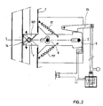
- the oven body 1 can be closed off by an articulated door 2, which door 2 is retained in the locked position and in the hooked position by a closure assembly 3 secured to the oven body.
- the closure assembly 3 comprises a fixed plate 4 provided with two transverse guide rods 5 and 6 perpendicular to the plate 4 and parallel to each other, spaced longitudinally along the longitudinal axis II of the device.
- a hook 7 is formed by a flat body 8 provided with an oblong posterior lumen 9 and an anterior lumen 10.
- the rod 5 slides with little play in the posterior lumen 9, while the rod 6 slides with little play in the anterior lumen 10.
- the oblong posterior lumen 9 is arranged along the longitudinal axis II of the device.
- the anterior lumen 10 is L-shaped, with a longitudinal branch 11 and a perpendicular L-shaped branch 12 connecting to the posterior part of the longitudinal branch 11.
- the anterior end of the flat hook body 8 protrudes outside the body oven 1, as shown in the figure, and includes a retaining housing 13 open upwards in which engages a lug 14 secured to the door 2, when the door is in the locking position and when the hook is in the position axial.
- the retaining ramp 15 limits the retaining housing 13 and forms a bearing surface for retaining the lug 14 in the locked position.
- a latching ramp 16 is provided on the front face of the hook to cooperate with the lug 14 when the door 2 is pushed towards the latching position.
- the perpendicular branch 12 of the anterior lumen 10 develops in the opening direction of the hook retaining housing 13.
- the hook 7 can slide longitudinally along the longitudinal axis II between a first position, or hooking position, shown in FIG. 1, in which the rods 5 and 6 bear against the rear ends of the rear lights 9 and anterior 10, and a second position or locking position in which the rods 5 and 6 are in abutment against the anterior ends of the openings 9 and 10.
- the branch 12 authorizes the pivoting of the hook 7 around the rod 5 according to a limited angular movement: in the position shown in FIG. 1, the lug 14 is housed in the retaining housing 13.
- the hook 7 pivots, the rod 6 coming into the bottom of the perpendicular branch 12, the hook releases the lug 14 which can then move along the longitudinal axis II, no longer being retained by the retaining ramp 15.
- the hook 7 is biased obliquely forward and upward by a tension spring 17, one end of which is fixed to the flat hook body 8 and the other end of which is fixed to the plate 4.
- the spring 17 tends to return the hook 7 to its axial position, along the longitudinal axis II when the latter has been moved laterally for the passage of the lug 14.
- the spring 17 also biases the hook 7 towards its anterior position d 'hooking shown in Figure 1, when it has been moved rearward in the locked position.
- the front part of the hook 7 comes out of the oven body 1 through a hole 18 formed in the wall of the oven body.
- the hook 7 comprises two protrusions 19 and 20, on either side of the hook 7, coming to bear against the front wall of the oven body 1 and thus closing the light 18 in the hooking position.
- the oven door 2 is provided with a push plate 21 which, when the door is brought from the hooking position towards the locking position, bears on the anterior end of the hook 7 to push the hook back to the locked position.
- the rear part of the flat hook body 8 7 includes an upper shoulder 22 intended to cooperate with a lower tooth 23 forming a movable stop and carried by a lever 24 rotating about a fixed axis 25 of the plate 4.
- the lever 24 is biased by an actuating rod 26 whose end comprises a core 27 of electromagnet 28 and a handle 29 for maneuvering.
- the electromagnet 28 is electrically connected in series on a power source 30 with a first switch 31 actuated by a door opening button 32 accessible by the user, and with a second switch 33 actuated by a ramp 34 of the hook 7.
- the second switch 33 is closed when the hook is in the locking position or back position, and is open when the hook is in all the other positions, and in particular in the hooking position shown in FIG. 1 .
- the operation of the device is as follows: in the open position, the hook 7 is in the position shown in Figure 1, in which it is brought by the spring 17, parallel to the longitudinal axis I-I.
- the lug 14 comes to bear on the interlocking ramp 16, and tends to move aside laterally the hook 7 retained longitudinally by the thrust exerted by the spring 17, allowing the passage of the lug 14 and its insertion into the retaining housing 13.
- the device is then in the hooking position, shown in FIG. 1. If the pushing of door 2 is continued, the pushing plate 21 pushes the hook 7 backwards, against the spring retaining force 17, and brings it into the locking position in which the rods 5 and 6 are in abutment in the front bottom of the slots 9 and 10.
- opening the door requires actuating the first switch 31, which powers the electromagnet 28 and lifts the lever 24 via the rod 26.
- the tooth 23 then leaves escape the shoulder 22, and the hook 7 returns to the hooking position under the action of the spring 17.
- the door 2 is then retained in this hooking position shown in Figure 1, position in which the lug 14 is engaged in the retaining housing 13.
- the complete opening of the door 2 requires pulling the door, to move the lug 14 longitudinally which is then in abutment against the retaining ramp 15, the movement of the lug 14 causing the hook 7 to pivot against the retaining force exerted by the spring 17.
- the hook 7 then returns to the latching position.
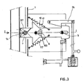
- FIGS. 2 an embodiment shown in FIGS. 2 can be used.
- the closure device comprises two identical hooks 7 and 107, arranged in symmetrical opposition relative to the longitudinal plane II, as shown in the figures.
- the two hooks 7 and 107 are guided by the same rods 5 and 6, retained by the same locking means such as the lever 24, and cooperate with the same lug 14 which they hold on either side in the locking position. shown in Figure 3 and in the hooking position shown in Figure 2.
- the hook 7 is biased by its spring 17 in an oblique position, while the hook 107 is biased by the spring 117 disposed in an oblique position symmetrically with respect to the spring 17.
- the operation of the two hooks 7 and 107 is symmetrical with respect to the plane II.
- FIG. 2 shows the position of the device with two hooks when the door is in the hanging position. Either hook can pivot around the rod 5 to engaging or disengaging the lug 14.
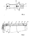
- FIG 4 there is shown the relative position of the hooks 7 and 107 during the passage of the lug 14 between the open position and the hooking position, the hooks 7 and 107 being spaced apart on either side of the longitudinal plane II, by rotation around the rod 5.
- FIG. 5 shows, in top view in partial section, an oven provided with a closing device according to the present invention.
- the oven body 1 has an opening 40 closed by the door 2.
- the door 2 comprises an outer wall 41 limited by a rigid frame 42 articulated on the oven body 1 along a vertical edge 43.
- the device closure 3 is arranged opposite the vertical articulation edge 43, and there are the hooks 7 and 107 cooperating with the lug 14 secured to a vertical upright of the frame 42.
- the door further comprises an inner plate 44, shaped to fit onto the opening 40 of the enclosure and close it in the closed position.
- the inner plate 44 is mounted on the outer wall 41 of the door, opposite its inner face 45, to which it is connected by connecting means allowing the relative movement of the inner plate 44 relative to the outer wall 41 of door parallel to the movement of said door around its articulations 43.
- the connection is ensured by guide rods such as rods 46 and 47, and compression springs pushing the inner plate 44 away from the outer wall 41, to bring it into abutment on rod stops 46 and 47 not shown.
- the stroke of the hooks 7 and 107 between their locking position and their hooking position is slightly greater than the stroke of the inner plate 44 relative to the outer wall 41. In this way, when unlocking, the door East brought into the hooking position in which the inner plate 44 slightly deviates from the body 1 of the oven and releases the gases and vapors contained inside the enclosure.
Landscapes
- Engineering & Computer Science (AREA)
- Mechanical Engineering (AREA)
- Chemical & Material Sciences (AREA)
- Combustion & Propulsion (AREA)
- General Engineering & Computer Science (AREA)
- Electric Ovens (AREA)
Applications Claiming Priority (2)
| Application Number | Priority Date | Filing Date | Title |
|---|---|---|---|
| FR8815209A FR2639096B1 (fr) | 1988-11-17 | 1988-11-17 | Fermeture pour four |
| FR8815209 | 1988-11-17 |
Publications (2)
| Publication Number | Publication Date |
|---|---|
| EP0369906A1 true EP0369906A1 (de) | 1990-05-23 |
| EP0369906B1 EP0369906B1 (de) | 1992-07-29 |
Family
ID=9372117
Family Applications (1)
| Application Number | Title | Priority Date | Filing Date |
|---|---|---|---|
| EP19890420443 Expired - Lifetime EP0369906B1 (de) | 1988-11-17 | 1989-11-15 | Backofen mit Verschluss |
Country Status (5)
| Country | Link |
|---|---|
| US (1) | US5012794A (de) |
| EP (1) | EP0369906B1 (de) |
| DE (1) | DE68902299T2 (de) |
| ES (1) | ES2034731T3 (de) |
| FR (1) | FR2639096B1 (de) |
Families Citing this family (32)
| Publication number | Priority date | Publication date | Assignee | Title |
|---|---|---|---|---|
| DE4040424A1 (de) * | 1990-12-18 | 1992-06-25 | Miele & Cie | Mikrowellenherd mit einer tuer |
| KR940007232B1 (ko) * | 1991-12-31 | 1994-08-10 | 대우전자 주식회사 | 전자렌지의 도어 개폐장치 |
| US5746456A (en) * | 1993-09-17 | 1998-05-05 | Societe Cooperative De Production Bourgeois | Oven door locking device |
| DE9401106U1 (de) * | 1994-01-24 | 1995-05-18 | Fischer Georg Gmbh & Co | Türverriegelung für einen Heizkessel für feste Brennstoffe |
| DE19629361C1 (de) * | 1996-07-20 | 1997-11-20 | Heraeus Instr Gmbh | Schloß |
| DE10027774C2 (de) * | 2000-04-20 | 2003-08-21 | Miwe Michael Wenz Gmbh | Vorrichtung zum Schließen der Tür eines Ofens und Ofen |
| US6315336B1 (en) * | 2000-05-30 | 2001-11-13 | Summit Manufacturing, Inc. | Motorized self-cleaning oven latch |
| US6474702B1 (en) | 2000-08-16 | 2002-11-05 | France/Scott Fetzer Company | Range door lock with nuisance latch |
| US7441812B2 (en) * | 2000-08-27 | 2008-10-28 | Southco, Inc. | Linear compression latch |
| EP1217117B1 (de) * | 2000-12-22 | 2005-03-02 | Elektromanufaktur Zangenstein, Hanauer GmbH & Co. KGaA | Vorrichtung zum Sperren und Freigeben eines Türschlosses eines elektrischen Gerätes |
| US7090263B2 (en) * | 2001-05-04 | 2006-08-15 | Spx Corporation | Door latching device and method |
| US6966582B1 (en) | 2001-11-02 | 2005-11-22 | France/Scott Fetzer Company | Lock rod clutch for oven latch |
| US7150480B2 (en) * | 2003-03-17 | 2006-12-19 | Maytag Corporation | Appliance lid lock and method for using same |
| DE102004002898A1 (de) * | 2004-01-20 | 2005-08-18 | Stolzlechner, Erwin, St. Johann | Automatische Schließeinrichtung für eine Ofentür |
| DE102004007122B4 (de) * | 2004-02-12 | 2006-11-16 | Miele & Cie. Kg | Verfahren zum Betreiben eines Gargeräts |
| US20050284460A1 (en) * | 2004-06-28 | 2005-12-29 | The Stanley Works | Oven door latch lock |
| DE102006001293B4 (de) * | 2006-01-10 | 2021-05-27 | BSH Hausgeräte GmbH | Gargerät und Verfahren zum Betreiben eines Gargeräts |
| US7334823B2 (en) * | 2006-05-05 | 2008-02-26 | Emerson Electric Co.. | Motorized oven lock having a reciprocating latch |
| DE102009019224B4 (de) * | 2008-04-30 | 2016-06-09 | Lg Electronics Inc. | Maschine zum Behandeln von Textil- und Lederwaren |
| US20100314889A1 (en) * | 2009-06-15 | 2010-12-16 | Solteam Electronics, Co., Ltd. | Latch assembly |
| JP2013527559A (ja) * | 2010-03-31 | 2013-06-27 | キーケルト アーゲー | 自動車用のアクチュエータおよび施錠装置および方法 |
| GB2480434B (en) * | 2010-05-17 | 2014-12-03 | Rolls Royce Plc | Toggle clamp locking device |
| US9958166B2 (en) * | 2012-05-31 | 2018-05-01 | Bsh Home Appliances Corporation | Household appliance having a latch retainer for an all glass inner door |
| KR101299634B1 (ko) * | 2013-06-13 | 2013-08-23 | 주식회사 중앙금속 | 잠금장치 |
| ITTO20130691A1 (it) * | 2013-08-13 | 2015-02-14 | Elbi Int Spa | Apparecchiatura per controllare la chiusura di una porta di un elettrodomestico, in particolare per una macchina lavatrice, quale una macchina lavastoviglie. |
| US10315842B2 (en) * | 2014-06-20 | 2019-06-11 | Western Disposal, Inc. | System for securing a lid of a container to prevent animal intrusion |
| KR102459278B1 (ko) * | 2016-06-20 | 2022-10-26 | 엘지전자 주식회사 | 잠금장치 및 이를 포함하는 가전기기 |
| CN107559907B (zh) * | 2016-06-30 | 2020-01-17 | 博西华电器(江苏)有限公司 | 抽油烟机 |
| DE202016103884U1 (de) | 2016-07-18 | 2016-09-06 | Rational Aktiengesellschaft | Gargerät mit Verriegelungsvorrichtung |
| CN108731054A (zh) * | 2017-04-25 | 2018-11-02 | 嵊州市惠宁达厨房电器有限公司 | 一种便于拆卸的油烟机罩 |
| DE102017111166A1 (de) * | 2017-05-22 | 2018-11-22 | Rahrbach Gmbh | Elektromechanische Verschlusseinrichtung für Gerätetüren |
| CN111288518B (zh) * | 2020-03-02 | 2022-01-25 | 宁波方太厨具有限公司 | 一种防脱挂钩组件及应用有该防脱挂钩组件的吸油烟机 |
Citations (4)
| Publication number | Priority date | Publication date | Assignee | Title |
|---|---|---|---|---|
| DE1906621B1 (de) * | 1969-02-11 | 1970-09-03 | Licentia Gmbh | Bratraumtuere fuer Kuechenherde |
| US3831580A (en) * | 1973-11-19 | 1974-08-27 | Corning Glass Works | Lockable oven door latch |
| US4163443A (en) * | 1977-08-15 | 1979-08-07 | Preway, Inc. | Latch mechanism for an oven door |
| US4554907A (en) * | 1983-12-12 | 1985-11-26 | Whirlpool Corporation | Latch for self-cleaning oven door |
Family Cites Families (1)
| Publication number | Priority date | Publication date | Assignee | Title |
|---|---|---|---|---|
| US4351288A (en) * | 1981-06-17 | 1982-09-28 | White Consolidated Industries, Inc. | Oven door latch |
-
1988
- 1988-11-17 FR FR8815209A patent/FR2639096B1/fr not_active Expired - Lifetime
-
1989
- 1989-11-15 EP EP19890420443 patent/EP0369906B1/de not_active Expired - Lifetime
- 1989-11-15 ES ES89420443T patent/ES2034731T3/es not_active Expired - Lifetime
- 1989-11-15 DE DE1989602299 patent/DE68902299T2/de not_active Expired - Fee Related
- 1989-11-17 US US07/438,625 patent/US5012794A/en not_active Expired - Lifetime
Patent Citations (4)
| Publication number | Priority date | Publication date | Assignee | Title |
|---|---|---|---|---|
| DE1906621B1 (de) * | 1969-02-11 | 1970-09-03 | Licentia Gmbh | Bratraumtuere fuer Kuechenherde |
| US3831580A (en) * | 1973-11-19 | 1974-08-27 | Corning Glass Works | Lockable oven door latch |
| US4163443A (en) * | 1977-08-15 | 1979-08-07 | Preway, Inc. | Latch mechanism for an oven door |
| US4554907A (en) * | 1983-12-12 | 1985-11-26 | Whirlpool Corporation | Latch for self-cleaning oven door |
Also Published As
| Publication number | Publication date |
|---|---|
| DE68902299D1 (de) | 1992-09-03 |
| FR2639096B1 (fr) | 1991-01-04 |
| ES2034731T3 (es) | 1993-04-01 |
| US5012794A (en) | 1991-05-07 |
| EP0369906B1 (de) | 1992-07-29 |
| DE68902299T2 (de) | 1993-02-04 |
| FR2639096A1 (fr) | 1990-05-18 |
Similar Documents
| Publication | Publication Date | Title |
|---|---|---|
| EP0369906B1 (de) | Backofen mit Verschluss | |
| CA2688143C (fr) | Dispositif de verrouillage d'une partie ouvrante de nacelle de turboreacteur par rapport a une partie fixe, et nacelle equipee d'un tel dispositif | |
| EP1081063B1 (de) | Vorrichtung zum automatisch durch Schwerkraft Verriegeln und Entriegeln des Deckels eines Behälters sowie Behälter mit einer derartigen Vorrichtung | |
| FR2669008A1 (fr) | Structure de couvercle. | |
| FR2652120A1 (fr) | Mecanisme de verrouillage pour porte coulissante. | |
| EP0911469B1 (de) | Drehbare Tür mit einem Flügel, an dem zwei parallele Treibstangen mittels zweiarmiger Hebel montiert sind | |
| FR2477991A1 (fr) | Dispositif de fixation d'une ferrure reglable dans differentes positions, en particulier d'une ferrure pour sieges de vehicule | |
| CA2696719A1 (fr) | Dispositif de verrouillage | |
| FR2734597A1 (fr) | Dispositif de degagement de verrou de maintien de porte ouverte et procede | |
| FR2782491A1 (fr) | Appareil de puericulture formant poussette et berceau | |
| CA1290208C (fr) | Porte guillotine perfectionnee pour foyer ferme de cheminee | |
| FR2641952A1 (fr) | Dispositif de fermeture au moyen d'un levier basculant et coulissant, notamment pour valises | |
| EP0002396B1 (de) | Lasthaken | |
| EP1104685B1 (de) | Automatische Snowboardbindung | |
| FR2738864A1 (fr) | Serrure a combinaison et bagage equipe de cette serrure | |
| FR2732062A1 (fr) | Serrure de porte assurant une fonction d'etancheite et une fonction de securite | |
| EP0704387B1 (de) | Sicherheitsvorrichtung, insbesondere Kindersicherheitsvorrichtung, für einen Müllsammelbehälter | |
| FR2650490A1 (de) | ||
| FR2736996A1 (fr) | Dispositif d'ouverture et de fermeture d'une porte d'acces a une enceinte, et four de cuisson equipe de ce dispositif | |
| FR2690478A1 (fr) | Foyer de cheminée à porte pivotante et escamotable. | |
| FR2697278A1 (fr) | Dispositif de verrouillage/déverrouillage pour portail à deux battants, et portail équipé d'un tel dispositif. | |
| FR2754163A1 (fr) | Friteuse a poignee rotative | |
| FR2627965A1 (fr) | Systeme de securite pour meuble a tiroirs | |
| FR2704737A1 (fr) | Cocotte à pression de vapeur avec une pièce de verrouillage de couvercle située sur l'extérieur de la cocotte. | |
| EP1033334A1 (de) | Sicherheitsvorrichtung für einen mit einem Deckel versehenen beräderten Behälter |
Legal Events
| Date | Code | Title | Description |
|---|---|---|---|
| PUAI | Public reference made under article 153(3) epc to a published international application that has entered the european phase |
Free format text: ORIGINAL CODE: 0009012 |
|
| AK | Designated contracting states |
Kind code of ref document: A1 Designated state(s): DE ES GB IT NL SE |
|
| 17P | Request for examination filed |
Effective date: 19901013 |
|
| 17Q | First examination report despatched |
Effective date: 19910328 |
|
| GRAA | (expected) grant |
Free format text: ORIGINAL CODE: 0009210 |
|
| AK | Designated contracting states |
Kind code of ref document: B1 Designated state(s): DE ES GB IT NL SE |
|
| REF | Corresponds to: |
Ref document number: 68902299 Country of ref document: DE Date of ref document: 19920903 |
|
| GBT | Gb: translation of ep patent filed (gb section 77(6)(a)/1977) | ||
| ITF | It: translation for a ep patent filed |
Owner name: MODIANO & ASSOCIATI S.R |
|
| REG | Reference to a national code |
Ref country code: ES Ref legal event code: FG2A Ref document number: 2034731 Country of ref document: ES Kind code of ref document: T3 |
|
| PLBE | No opposition filed within time limit |
Free format text: ORIGINAL CODE: 0009261 |
|
| STAA | Information on the status of an ep patent application or granted ep patent |
Free format text: STATUS: NO OPPOSITION FILED WITHIN TIME LIMIT |
|
| 26N | No opposition filed | ||
| EAL | Se: european patent in force in sweden |
Ref document number: 89420443.7 |
|
| PGFP | Annual fee paid to national office [announced via postgrant information from national office to epo] |
Ref country code: SE Payment date: 19951024 Year of fee payment: 7 |
|
| PGFP | Annual fee paid to national office [announced via postgrant information from national office to epo] |
Ref country code: GB Payment date: 19961107 Year of fee payment: 8 |
|
| PGFP | Annual fee paid to national office [announced via postgrant information from national office to epo] |
Ref country code: ES Payment date: 19961111 Year of fee payment: 8 |
|
| PG25 | Lapsed in a contracting state [announced via postgrant information from national office to epo] |
Ref country code: SE Effective date: 19961116 |
|
| PGFP | Annual fee paid to national office [announced via postgrant information from national office to epo] |
Ref country code: NL Payment date: 19961130 Year of fee payment: 8 |
|
| PGFP | Annual fee paid to national office [announced via postgrant information from national office to epo] |
Ref country code: DE Payment date: 19961227 Year of fee payment: 8 |
|
| EUG | Se: european patent has lapsed |
Ref document number: 89420443.7 |
|
| PG25 | Lapsed in a contracting state [announced via postgrant information from national office to epo] |
Ref country code: GB Free format text: LAPSE BECAUSE OF NON-PAYMENT OF DUE FEES Effective date: 19971115 |
|
| PG25 | Lapsed in a contracting state [announced via postgrant information from national office to epo] |
Ref country code: ES Free format text: LAPSE BECAUSE OF NON-PAYMENT OF DUE FEES Effective date: 19971116 |
|
| PG25 | Lapsed in a contracting state [announced via postgrant information from national office to epo] |
Ref country code: NL Free format text: LAPSE BECAUSE OF NON-PAYMENT OF DUE FEES Effective date: 19980601 |
|
| GBPC | Gb: european patent ceased through non-payment of renewal fee |
Effective date: 19971115 |
|
| PG25 | Lapsed in a contracting state [announced via postgrant information from national office to epo] |
Ref country code: DE Free format text: LAPSE BECAUSE OF NON-PAYMENT OF DUE FEES Effective date: 19980801 |
|
| NLV4 | Nl: lapsed or anulled due to non-payment of the annual fee |
Effective date: 19980601 |
|
| REG | Reference to a national code |
Ref country code: ES Ref legal event code: FD2A Effective date: 19981212 |
|
| PG25 | Lapsed in a contracting state [announced via postgrant information from national office to epo] |
Ref country code: IT Free format text: LAPSE BECAUSE OF NON-PAYMENT OF DUE FEES;WARNING: LAPSES OF ITALIAN PATENTS WITH EFFECTIVE DATE BEFORE 2007 MAY HAVE OCCURRED AT ANY TIME BEFORE 2007. THE CORRECT EFFECTIVE DATE MAY BE DIFFERENT FROM THE ONE RECORDED. Effective date: 20051115 |