EP0369866A1 - Steuervorrichtung für einen sich bewegenden Körper - Google Patents
Steuervorrichtung für einen sich bewegenden Körper Download PDFInfo
- Publication number
- EP0369866A1 EP0369866A1 EP89403108A EP89403108A EP0369866A1 EP 0369866 A1 EP0369866 A1 EP 0369866A1 EP 89403108 A EP89403108 A EP 89403108A EP 89403108 A EP89403108 A EP 89403108A EP 0369866 A1 EP0369866 A1 EP 0369866A1
- Authority
- EP
- European Patent Office
- Prior art keywords
- mobile member
- speed
- motor
- lower limit
- presetting
- Prior art date
- Legal status (The legal status is an assumption and is not a legal conclusion. Google has not performed a legal analysis and makes no representation as to the accuracy of the status listed.)
- Granted
Links
Images


Classifications
-
- G—PHYSICS
- G05—CONTROLLING; REGULATING
- G05B—CONTROL OR REGULATING SYSTEMS IN GENERAL; FUNCTIONAL ELEMENTS OF SUCH SYSTEMS; MONITORING OR TESTING ARRANGEMENTS FOR SUCH SYSTEMS OR ELEMENTS
- G05B19/00—Programme-control systems
- G05B19/02—Programme-control systems electric
- G05B19/18—Numerical control [NC], i.e. automatically operating machines, in particular machine tools, e.g. in a manufacturing environment, so as to execute positioning, movement or co-ordinated operations by means of programme data in numerical form
- G05B19/416—Numerical control [NC], i.e. automatically operating machines, in particular machine tools, e.g. in a manufacturing environment, so as to execute positioning, movement or co-ordinated operations by means of programme data in numerical form characterised by control of velocity, acceleration or deceleration
Definitions
- the present invention relates to a mobile member control apparatus, and more particularly relates to a control apparatus for controlling speed and position of a mobile member, such as an optical system in an electrophotographic copying machine and an original reading/writing head in a facsimile device.
- the present invention provides a mobile member control apparatus having a motor for accelerating a mobile member to move it from a first position, decelerating the mobile member after it reaches a second position and stopping the mobile member at a third position, comprising speed sensing means for sensing a travel speed of the mobile member; position detecting means for detecting a position of the mobile member; speed presetting means for presetting upper and lower limit values in speed, the upper and lower limit values being given by a function about a displacement of the mobile member and becoming smaller as the mobile member travels closer to the third position; deceleration rate presetting means for presetting at least two deceleration rates, large and small; comparing means for comparing comparing a travel speed received from the speed sensing means with the upper and lower limit values; motor control means for decelerating the motor according to either of the large or small deceleration rate when the position detecting means detects that the mobile member reaches the second position, decelerating the motor according to the large deceleration rate when a travel speed
- the present invention further provides a mobile member control apparatus having a motor for accelerating a mobile member to move it from a first position and decelerating the mobile member to stop it at a second position, comprising speed sensing means for sensing a travel speed of the mobile member; position detecting means for detecting a position of the mobile member; speed presetting means for presetting upper and lower limit values in speed which is given by a function about a displacement of the mobile member and which become smaller as the mobile member travels closer to the second position; first comparing means for comparing a travel speed received from the speed sensing means with the upper and lower limit values; deceleration start speed presetting means for presetting a speed at which deceleration is started, the deceleration start speed being a value between the upper and lower limit values, being given as a function of a displacement of the mobile member and becoming smaller as the mobile member travels closer to the second position; second comparing means for comparing a travel speed received from the speed sensing means with the deceleration
- the aforementioned upper and lower limit values in speed and the deceleraion start speed can be determined by a linear function of a displacement of the mobile member.
- the motor control means preferably accelerates and decelerates the motor by a PWM control, although not limited to that.
- the speed sensing means and the position detecting means are formed of a rotary encoder, for example, which is connected to the motor.
- the mobile member control apparatus includes a microcomputer having a ROM, a RAM, a CPU, etc.
- the microcomputer serves as the speed presetting means, the deceleration rate presetting means, the comparing means, the deceleration start speed presetting means and the motor control means.
- FIGs. 1 and 2 are block diagrams showing a basic architecture of each of control devices according to the present invention.
- the control device shown in Fig. 1 comprises speed sensing means 101 for sensing a travel speed of a mobile member which travels from a first position through a second position to a third position, position detecting means 102 for detecting of the mobile member, upper and lower limit speed presetting means 103 for presetting upper and lower limit values in speed which are given as a linear function about a distance from a position where the mobile member is to the third position and which become small as the mobile member travels closer to the third position, deceleration rate presetting means 104 for presetting at least two deceleration rates, large and small, comparing means 105 for comparing a travel speed received from the speed sensing means 101 with the upper and lower limit values, and motor control means 106 for decelerating a motor 107 according to either of the large or small deceleration rates when the mobile member reaches the second position, decelerating the motor 107 according to the large deceleration rate when the travel speed of the mobile member reaches the upper limit value and decelerating the
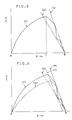
- Fig. 3 is a graph showing relations between position P (on an axis of abscissas) and speed V (on an axis of ordinates) of the mobile member with a curve (f).
- the mobile member accelerates from the first position A, decelerates after it reaches the second position C and stops at the third position B.
- (a) and (b) are functions which represent the upper and lower limit values in speed preset in the upper and lower limit speed presetting means 103, respectively.
- the control means decelerates the motor according to either of the large or small deceleration rates (the small deceleration rate in this case) preset in the deceleration presetting means 104.
- the comparing means 105 compares a speed of the mobile member with the upper and lower limit values in speed given as the functions (a), (b), so that the motor 107 is decelerated according to the large deceleration rate when the travel speed of the mobile member reaches the upper limit value, and the motor 107 is decelerated according to the small deceleration rate when the travel speed of the mobile member reaches the lower limit value.
- the reduction of speed V of the mobile member varies in a region between functions (a), (b), and eventually the mobile member stops at the third position B with high accuracy. Decelerating the mobile member in the above mentioned manner, the burden for the control apparatus can be lightened because the mobile member can be stopped at a predetermined position with high accuracy without calculating a deceleration rate in each of predetermined sections and controlling the speed of the mobile member every time.
- the control apparatus shown in Fig. 2 comprises speed sensing means 201 for sensing a travel speed of a mobile member which travels from a first position to a second position, position detecting means 202 for detecting a position of the mobile member, upper and lower limit speed presetting means 203 for presetting upper and lower limit values in speed which are given as a linear function about a distance from a position where the mobile member is to the second position and which become small as the mobile member travels closer to the second position, first comparing means 204 for comparing a travel speed received from the speed sensing means 201 with the upper and lower limit values in speed in relation to the position of the mobile member, deceleration start speed presetting means 205 for presetting a speed of the mobile member at which deceleration is started between the upper and lower limit values in speed, which is given as a linear function about a displacement of the mobile member to the second position and which becomes smaller as the mobile member travels closer to the second position, second comparing means 206 for comparing a travel speed received from the speed sens
- Fig. 4 is a graph showing relations between position P and speed V of the mobile member with a curve (f) similar to that of Fig. 3.
- the curve (f) shows a situation in which the mobile member accelerates from the first position A, and then it decelerates and stops at the second position B.
- (a) and (b) are functions representing the upper and lower limit values in speed which are preset in the upper and lower limit speed presetting means 203, respectively.
- (c) is a function representing a speed at which deceleration is started and the speed is preset at the deceleration start speed presetting means 205.
- Speed and position of the mobile member are detected by the speed sensing means 201 and the position detecting means 202.
- the control means 208 decelerates the motor 209 according to either of the large or small deceleration rates (the small deceleration rate in this case) preset in the deceleration rate presetting means 207.
- the control means 208 decelerates the motor 209 according to the large deceleration rate. Further, the control means 208 decelerates the motor 209 according to the small deceleration rate when the travel speed of the mobile member reaches the lower limit value (b).
- a curve (g) shows relations between position P and speed V in the case where a variation in load, for example, makes a speed of the mobile member which is accelerating change. Similar to the case with the curve (f), deceleration is started after a speed of the mobile member reaches a value determined by the function (c) to reduce the speed V between the functions (a) and (b) so that the mobile member stops at the second position B with high accuracy.
- the control means controls the mobile member in the above mentioned manner, there is no need for the control means to calculate a deceleration rate in each of many sections, so that the burden for the control means is lightened. Further, even if an acceleration condition of the mobile member varies in accordance with a variation in load, for example, a deceleration start speed is determined accordingly, so that braking is controlled with high accuracy.
- control device according to the present invention is applied to an electrophotographic copying machine to control the movement of an optical system will be described in detail.
- Fig. 5 is a perspective view showing a main portion of the optical system in the electrophotographic copying machine.
- the optical system comprises a lamp unit 1 holding an exposure lamp for exposing an original to light, a mirror unit 2 for reflecting the light reflected from the original to a photosensitive drum (not shown), a shaft 3 for slidably supporting one end of each of the lamp unit 1 and the mirror unit 2, a guide plate 4 for slidably supporting the other end of each of the lamp unit 1 and the mirror unit 2, a motor M, a driving pulley 5 connected to an output shaft of the motor M, pulleys 6, 7, 8 held in the body of the copying machine, a wire 9 having its one end connected to the driving pulley 5 and the other end connected to a holding member 9a, and extending between the fixed pulley 6 and a pulley 2a attached to the mirror unit 2, a wire 10 having its one end connected to the driving pulley 5 and the other end connected to a holding member 10a, and extending among the pulley
- the lamp unit 1 and the mirror unit 2 travel in a forward direction shown in an arrow A to expose and scan the original when the motor M rotates in the counterclockwise direction with regard to the shaft (forward rotation), or they travel in a reverse direction shown in an arrow B to return to the original position when the motor M rotates in the clockwise direction (reverse rotation).
- a travel speed of the mirror unit 2 is half of that of the lamp unit 1.
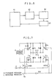
- Fig. 6 is a block diagram showing a control unit of the embodiment shown in Fig. 5.
- the control unit comprises a control circuit 11 including a microcomputer made up of a RAM, a ROM, a CPU, etc., a power amplifier 12 for driving the motor M, and a rotary encoder 13 connected to the motor M.
- Fig. 7 is a circuit diagram showing the power amplifier 12 shown in Fig. 6.
- the power amplifier 12 comprises a power source E, power transistors TR1 to TR4, diodes D1 to D4, resistances R1 to R4, AND gates AND1, AND2, an inverter INV, and input terminals Ta, Tb.
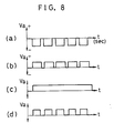
- Fig. 8 shows examples of a waveform of voltage Va at a terminal of the motor M: Fig. 8(a) shows a waveform of voltage applied to the motor M when the motor M is driven in the reverse direction, Fig. 8(b) shows a waveform of voltage applied when the motor M rotating in the reverse direction is controlled by 80% braking, Fig. 8(c) shows a waveform of voltage applied to the motor M when the motor M rotating in the reverse direction is controlled by full braking, and Fig. 8(d) shows a waveform of voltage applied to the motor M when the motor M rotating in the reverse direction is controlled by 60% braking.
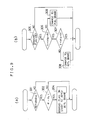
- the operation of the control apparatus which has the aforementioned constitution will be described in conjunction with flow charts in Fig. 9 and a graph in Fig.
- Fig. 10 showing relations between position P and speed V with a P-V curve.
- Fig. 10 is a graph in which values corresponding to position P of the lamp unit 1 (or of the mirror unit 2) are on an axis of abscissas and those corresponding to its speed V are on an axis of ordinates where positive numbers corresponds to positions during the movement in the forward direction.
- the motor M starts and rotates in the forward direction at a predetermined speed.
- voltage shown in Fig. 8(a) is applied to the motor M.
- step 302 This allows the motor M to rotate reversely, so that the lamp unit 1 travels in the reverse direction with its speed increased (step 301).
- a braking flag turns ON in the control circuit 11 and voltage of the waveform shown in Fig. 8(b) is applied to the motor M.
- step 304 80% braking
- step 305 While the braking flag is ON, namely, while the motor M is being controlled by braking (step 305), the speed V, the upper limit value in speed (a1P + b1) and the lower limit value (a2P + b2) are all compared one another, and V > a2P + b2 is obtained (step 306).
- V ⁇ a1P + b1 If V ⁇ a1P + b1 (step 307), the control of the motor by 80% braking is continued. On the other hand, if V ⁇ a1P + b1, voltage shown in Fig. 8(d) is applied to the motor M, and the motor M is controlled by 60% braking (step 308). Meanwhile, when the speed V reaches the lower limit value, namely, when V ⁇ a2P + b2 (step 306), voltage shown in Fig. 8(c) is applied to the motor M, and the motor M is controlled by full braking. Thus, the motor M is controlled by 80%, 60% or full braking to decelerate between the upper and lower limit values.
- a point where braking is started is accordingly set at a position close to the original position. Conversely, if the speed V increases as the load is reduced, braking is started at a point apart from the original position. Therefore, even if the speed of the motor varies as the load varies, a point where braking is started is determined according to circumstances, so that the lamp unit 1 is braked without difficulties.
- the lamp unit 1 can return to the original position with high accuracy by simply braking the motor M according to a predetermined deceleration rate when the speed V of the lamp unit 1 reaches either of the upper or lower limit values. Accordingly, there is no need to calculate a deceleration rate in each of predetermined sections. Further, appropriate braking with high accuracy is attained, because even if the load varies while the lamp unit 1 is returning, a point where braking is started is accordingly determined.
- the control apparatus there is no need for the control apparatus to calculate relations between a position and a deceleration rate of a mobile member in each of sections when the mobile member is braked. Further, the mobile member is braked appropriately with high accuracy, because even if the load of the mobile member varies, a point where braking is started is accordingly determined.
Applications Claiming Priority (2)
| Application Number | Priority Date | Filing Date | Title |
|---|---|---|---|
| JP63286341A JPH0786776B2 (ja) | 1988-11-12 | 1988-11-12 | 移動体の制御装置 |
| JP286341/88 | 1988-11-12 |
Publications (2)
| Publication Number | Publication Date |
|---|---|
| EP0369866A1 true EP0369866A1 (de) | 1990-05-23 |
| EP0369866B1 EP0369866B1 (de) | 1994-04-27 |
Family
ID=17703132
Family Applications (1)
| Application Number | Title | Priority Date | Filing Date |
|---|---|---|---|
| EP89403108A Expired - Lifetime EP0369866B1 (de) | 1988-11-12 | 1989-11-10 | Steuervorrichtung für einen sich bewegenden Körper |
Country Status (4)
| Country | Link |
|---|---|
| US (1) | US5017850A (de) |
| EP (1) | EP0369866B1 (de) |
| JP (1) | JPH0786776B2 (de) |
| DE (1) | DE68914947T2 (de) |
Cited By (1)
| Publication number | Priority date | Publication date | Assignee | Title |
|---|---|---|---|---|
| WO1993002405A1 (en) * | 1991-07-22 | 1993-02-04 | United Technologies Corporation | Adaptive control system input limiting |
Families Citing this family (4)
| Publication number | Priority date | Publication date | Assignee | Title |
|---|---|---|---|---|
| FR2653902B1 (de) * | 1989-10-27 | 1994-03-11 | Asahi Kogaku Kogyo Kk | |
| IT1260518B (it) * | 1992-06-03 | 1996-04-09 | Claudio Locatelli | Procedimento e dispositivo per il controllo di una macchina pettinatrice |
| US5451851A (en) * | 1993-12-06 | 1995-09-19 | Delco Electronics Corp. | Method and apparatus for one wire motor speed and direction decoding |
| JPH10248295A (ja) * | 1997-03-03 | 1998-09-14 | Zexel Corp | アクチュエータ制御装置 |
Citations (4)
| Publication number | Priority date | Publication date | Assignee | Title |
|---|---|---|---|---|
| DE2334455A1 (de) * | 1973-07-06 | 1975-01-23 | Siemens Ag | Verfahren und schaltungsanordnung zum abbremsen eines numerisch gesteuerten antriebs |
| US4254371A (en) * | 1978-08-28 | 1981-03-03 | Am International, Inc. | Photocomposer escapement carriage control |
| DE3333007A1 (de) * | 1982-09-13 | 1984-03-15 | Ricoh Co., Ltd., Tokyo | System zum steuern eines servomotors |
| US4460968A (en) * | 1981-10-16 | 1984-07-17 | International Business Machines Corporation | Print head motor control with stop distance compensation |
Family Cites Families (5)
| Publication number | Priority date | Publication date | Assignee | Title |
|---|---|---|---|---|
| US4337428A (en) * | 1980-09-08 | 1982-06-29 | Bodine Electric Company | Deceleration initiation circuit for a stepper motor |
| JPS5917472A (ja) * | 1982-07-21 | 1984-01-28 | 三菱電機株式会社 | エレベ−タの速度パタ−ン発生装置 |
| DE3422351A1 (de) * | 1983-06-16 | 1984-12-20 | Canon K.K., Tokio/Tokyo | Bilderzeugungssystem |
| US4751984A (en) * | 1985-05-03 | 1988-06-21 | Otis Elevator Company | Dynamically generated adaptive elevator velocity profile |
| US4698567A (en) * | 1985-12-27 | 1987-10-06 | Xerox Corporation | Ribbon deck motor control |
-
1988
- 1988-11-12 JP JP63286341A patent/JPH0786776B2/ja not_active Expired - Lifetime
-
1989
- 1989-11-09 US US07/433,903 patent/US5017850A/en not_active Expired - Fee Related
- 1989-11-10 EP EP89403108A patent/EP0369866B1/de not_active Expired - Lifetime
- 1989-11-10 DE DE68914947T patent/DE68914947T2/de not_active Expired - Fee Related
Patent Citations (4)
| Publication number | Priority date | Publication date | Assignee | Title |
|---|---|---|---|---|
| DE2334455A1 (de) * | 1973-07-06 | 1975-01-23 | Siemens Ag | Verfahren und schaltungsanordnung zum abbremsen eines numerisch gesteuerten antriebs |
| US4254371A (en) * | 1978-08-28 | 1981-03-03 | Am International, Inc. | Photocomposer escapement carriage control |
| US4460968A (en) * | 1981-10-16 | 1984-07-17 | International Business Machines Corporation | Print head motor control with stop distance compensation |
| DE3333007A1 (de) * | 1982-09-13 | 1984-03-15 | Ricoh Co., Ltd., Tokyo | System zum steuern eines servomotors |
Cited By (2)
| Publication number | Priority date | Publication date | Assignee | Title |
|---|---|---|---|---|
| WO1993002405A1 (en) * | 1991-07-22 | 1993-02-04 | United Technologies Corporation | Adaptive control system input limiting |
| AU657157B2 (en) * | 1991-07-22 | 1995-03-02 | United Technologies Corporation | Adaptive control system input limiting |
Also Published As
| Publication number | Publication date |
|---|---|
| DE68914947D1 (de) | 1994-06-01 |
| DE68914947T2 (de) | 1994-08-11 |
| EP0369866B1 (de) | 1994-04-27 |
| JPH0786776B2 (ja) | 1995-09-20 |
| US5017850A (en) | 1991-05-21 |
| JPH02132506A (ja) | 1990-05-22 |
Similar Documents
| Publication | Publication Date | Title |
|---|---|---|
| US4436416A (en) | Mirror scanning control mechanism in variable magnification type copying machine | |
| US5017850A (en) | Mobile member control apparatus | |
| US6031633A (en) | Control method of scanner optical system of original image reading apparatus, motor control device and moving unit driving device of image reading apparatus | |
| US4693595A (en) | Method of controlling a stop position of an optical system in a copying machine | |
| JP3306082B2 (ja) | スキャナ光学系の制御方法 | |
| JPH10201276A (ja) | 画像形成装置のスキャナにおけるサーボ制御装置 | |
| JPH0522975A (ja) | モータの駆動制御方法および装置 | |
| JP3556390B2 (ja) | 画像形成装置の光学系の駆動方法 | |
| JP3815590B2 (ja) | 画像読み取り装置の駆動方法 | |
| JPS6059342A (ja) | 光学装置の駆動制御方法 | |
| JP2551590B2 (ja) | 複写機光学系の速度制御方法 | |
| JP3302747B2 (ja) | 走行体駆動装置 | |
| JPS63154083A (ja) | 複写機における移動体駆動源モ−タの制御装置 | |
| JPS6083110A (ja) | 位置制御機械の原点検出方式 | |
| JPH06113576A (ja) | モータ制御装置 | |
| JPH0965059A (ja) | 画像読取装置 | |
| JPH04347842A (ja) | スキャナ制御装置 | |
| JP3187088B2 (ja) | スキャナ駆動方法及びその装置 | |
| JPH11150975A (ja) | スキャナ用サーボ制御装置 | |
| JPH04133047A (ja) | スキャナ光学系の制御装置 | |
| KR930004925A (ko) | 복사기의 스캐너 리턴 제어 방법 | |
| JP3576581B2 (ja) | スキャナ制御装置 | |
| JPH0534837A (ja) | 複写機 | |
| JPH05229781A (ja) | クレーン走行端における速度制御方法 | |
| JPH05100324A (ja) | 光学系走行体駆動モータの制御方法 |
Legal Events
| Date | Code | Title | Description |
|---|---|---|---|
| PUAI | Public reference made under article 153(3) epc to a published international application that has entered the european phase |
Free format text: ORIGINAL CODE: 0009012 |
|
| AK | Designated contracting states |
Kind code of ref document: A1 Designated state(s): DE FR GB NL |
|
| 17P | Request for examination filed |
Effective date: 19901112 |
|
| 17Q | First examination report despatched |
Effective date: 19930503 |
|
| GRAA | (expected) grant |
Free format text: ORIGINAL CODE: 0009210 |
|
| AK | Designated contracting states |
Kind code of ref document: B1 Designated state(s): DE FR GB NL |
|
| REF | Corresponds to: |
Ref document number: 68914947 Country of ref document: DE Date of ref document: 19940601 |
|
| ET | Fr: translation filed | ||
| PLBE | No opposition filed within time limit |
Free format text: ORIGINAL CODE: 0009261 |
|
| STAA | Information on the status of an ep patent application or granted ep patent |
Free format text: STATUS: NO OPPOSITION FILED WITHIN TIME LIMIT |
|
| 26N | No opposition filed | ||
| PGFP | Annual fee paid to national office [announced via postgrant information from national office to epo] |
Ref country code: GB Payment date: 19951101 Year of fee payment: 7 |
|
| PGFP | Annual fee paid to national office [announced via postgrant information from national office to epo] |
Ref country code: FR Payment date: 19951109 Year of fee payment: 7 |
|
| PGFP | Annual fee paid to national office [announced via postgrant information from national office to epo] |
Ref country code: DE Payment date: 19951113 Year of fee payment: 7 |
|
| PGFP | Annual fee paid to national office [announced via postgrant information from national office to epo] |
Ref country code: NL Payment date: 19951129 Year of fee payment: 7 |
|
| PG25 | Lapsed in a contracting state [announced via postgrant information from national office to epo] |
Ref country code: GB Effective date: 19961110 |
|
| PG25 | Lapsed in a contracting state [announced via postgrant information from national office to epo] |
Ref country code: NL Effective date: 19970601 |
|
| GBPC | Gb: european patent ceased through non-payment of renewal fee |
Effective date: 19961110 |
|
| PG25 | Lapsed in a contracting state [announced via postgrant information from national office to epo] |
Ref country code: FR Effective date: 19970731 |
|
| NLV4 | Nl: lapsed or anulled due to non-payment of the annual fee |
Effective date: 19970601 |
|
| PG25 | Lapsed in a contracting state [announced via postgrant information from national office to epo] |
Ref country code: DE Effective date: 19970801 |
|
| REG | Reference to a national code |
Ref country code: FR Ref legal event code: ST |