EP0366153B1 - Liquid crystal apparatus - Google Patents
Liquid crystal apparatus Download PDFInfo
- Publication number
- EP0366153B1 EP0366153B1 EP89120038A EP89120038A EP0366153B1 EP 0366153 B1 EP0366153 B1 EP 0366153B1 EP 89120038 A EP89120038 A EP 89120038A EP 89120038 A EP89120038 A EP 89120038A EP 0366153 B1 EP0366153 B1 EP 0366153B1
- Authority
- EP
- European Patent Office
- Prior art keywords
- signal
- scanning
- data
- electrodes
- liquid crystal
- Prior art date
- Legal status (The legal status is an assumption and is not a legal conclusion. Google has not performed a legal analysis and makes no representation as to the accuracy of the status listed.)
- Expired - Lifetime
Links
Images


Classifications
-
- G—PHYSICS
- G09—EDUCATION; CRYPTOGRAPHY; DISPLAY; ADVERTISING; SEALS
- G09G—ARRANGEMENTS OR CIRCUITS FOR CONTROL OF INDICATING DEVICES USING STATIC MEANS TO PRESENT VARIABLE INFORMATION
- G09G3/00—Control arrangements or circuits, of interest only in connection with visual indicators other than cathode-ray tubes
- G09G3/04—Control arrangements or circuits, of interest only in connection with visual indicators other than cathode-ray tubes for presentation of a single character by selection from a plurality of characters, or by composing the character by combination of individual elements, e.g. segments using a combination of such display devices for composing words, rows or the like, in a frame with fixed character positions
- G09G3/16—Control arrangements or circuits, of interest only in connection with visual indicators other than cathode-ray tubes for presentation of a single character by selection from a plurality of characters, or by composing the character by combination of individual elements, e.g. segments using a combination of such display devices for composing words, rows or the like, in a frame with fixed character positions by control of light from an independent source
- G09G3/18—Control arrangements or circuits, of interest only in connection with visual indicators other than cathode-ray tubes for presentation of a single character by selection from a plurality of characters, or by composing the character by combination of individual elements, e.g. segments using a combination of such display devices for composing words, rows or the like, in a frame with fixed character positions by control of light from an independent source using liquid crystals
-
- G—PHYSICS
- G09—EDUCATION; CRYPTOGRAPHY; DISPLAY; ADVERTISING; SEALS
- G09G—ARRANGEMENTS OR CIRCUITS FOR CONTROL OF INDICATING DEVICES USING STATIC MEANS TO PRESENT VARIABLE INFORMATION
- G09G3/00—Control arrangements or circuits, of interest only in connection with visual indicators other than cathode-ray tubes
- G09G3/20—Control arrangements or circuits, of interest only in connection with visual indicators other than cathode-ray tubes for presentation of an assembly of a number of characters, e.g. a page, by composing the assembly by combination of individual elements arranged in a matrix no fixed position being assigned to or needed to be assigned to the individual characters or partial characters
- G09G3/34—Control arrangements or circuits, of interest only in connection with visual indicators other than cathode-ray tubes for presentation of an assembly of a number of characters, e.g. a page, by composing the assembly by combination of individual elements arranged in a matrix no fixed position being assigned to or needed to be assigned to the individual characters or partial characters by control of light from an independent source
- G09G3/36—Control arrangements or circuits, of interest only in connection with visual indicators other than cathode-ray tubes for presentation of an assembly of a number of characters, e.g. a page, by composing the assembly by combination of individual elements arranged in a matrix no fixed position being assigned to or needed to be assigned to the individual characters or partial characters by control of light from an independent source using liquid crystals
- G09G3/3611—Control of matrices with row and column drivers
- G09G3/3622—Control of matrices with row and column drivers using a passive matrix
- G09G3/3629—Control of matrices with row and column drivers using a passive matrix using liquid crystals having memory effects, e.g. ferroelectric liquid crystals
-
- G—PHYSICS
- G09—EDUCATION; CRYPTOGRAPHY; DISPLAY; ADVERTISING; SEALS
- G09G—ARRANGEMENTS OR CIRCUITS FOR CONTROL OF INDICATING DEVICES USING STATIC MEANS TO PRESENT VARIABLE INFORMATION
- G09G2310/00—Command of the display device
- G09G2310/02—Addressing, scanning or driving the display screen or processing steps related thereto
- G09G2310/0224—Details of interlacing
- G09G2310/0227—Details of interlacing related to multiple interlacing, i.e. involving more fields than just one odd field and one even field
-
- G—PHYSICS
- G09—EDUCATION; CRYPTOGRAPHY; DISPLAY; ADVERTISING; SEALS
- G09G—ARRANGEMENTS OR CIRCUITS FOR CONTROL OF INDICATING DEVICES USING STATIC MEANS TO PRESENT VARIABLE INFORMATION
- G09G2310/00—Command of the display device
- G09G2310/02—Addressing, scanning or driving the display screen or processing steps related thereto
- G09G2310/0232—Special driving of display border areas
-
- G—PHYSICS
- G09—EDUCATION; CRYPTOGRAPHY; DISPLAY; ADVERTISING; SEALS
- G09G—ARRANGEMENTS OR CIRCUITS FOR CONTROL OF INDICATING DEVICES USING STATIC MEANS TO PRESENT VARIABLE INFORMATION
- G09G2320/00—Control of display operating conditions
- G09G2320/04—Maintaining the quality of display appearance
- G09G2320/041—Temperature compensation
Definitions
- the present invention relates to a liquid crystal apparatus using a ferroelectric liquid crystal material and, more particularly, to a liquid crystal apparatus which can suppress a flicker generated in a display drive operation at a low temperature.
- a liquid crystal display element In a known liquid crystal display element, scanning electrodes and signal electrodes are arranged in a matrix, and a liquid crystal compound is filled between these electrodes to form a large number of pixels so as to display an image or information.
- a time-divisional driving method is adopted. In this method, address signals are sequentially, periodically, and selectively applied to the scanning electrodes, and a predetermined information signal is parallelly and selectively applied to the signal electrodes in synchronism with the address signals.
- TN Transmission Nematic
- a liquid crystal element having bistability is proposed in, e.g., Japanese Patent Laid-Open (Kokai) JP-A-56107216 and U.S. Patent US-A-4,367,924 by Clark and Lagerwall.
- a bistable liquid crystal a ferroelectric liquid crystal having a chiral smectic C phase (SmC*) or H phase (SmH*) is used.
- SmC* chiral smectic C phase
- SmH* H phase
- the ferroelectric liquid crystal takes a first or second optically stable state in response to an applied electric field, and maintains the state when no electric field is applied. That is, the ferroelectric liquid crystal has bistability, and is expected to be widely used in the field of high-speed storage type display apparatuses having a quick response property with respect to a change in electric field.
- the ferroelectric liquid crystal element is driven by driving apparatuses disclosed in, e.g., U.S. Patent US-A-4,548,476, US-A-4,665,561, US-A-4,697,887, US-A-4,709,995, US-A-4,712,872.
- threshold characteristics of a ferroelectric liquid crystal largely depend on an external temperature, as shown in Fig. 10. More specifically, as a temperature becomes lower, an applied voltage necessary for inversion is increased and a voltage application time is prolonged.
- a ferroelectric liquid crystal must increase a drive pulse width (scanning selection period) in a driving operation at a low temperature as compared to a scanning driving operation at a frame frequency of 15 Hz at a high temperature.
- the ferroelectric liquid crystal requires a scanning driving operation at a low frame frequency of, e.g., 5 to 10 Hz. For this reason, in a driving operation at a low temperature, a flicker caused by the scanning driving operation at a low frame frequency occurs.
- Document EP-A-0 149 899 discloses a liquid crystal apparatus comprising a liquid crystal element having a matrix of electrodes including scanning electrodes and information electrodes.
- Driving means include means for applying a scanning selection signal to the scanning signal electrodes and means for applying an information signal to the information signal electrodes in synchronism with the scanning selection signal.
- the control means operates in a time sharing mode.
- an object of the present invention to provide a liquid crystal apparatus with high-quality display wherein the generation of a flicker is suppressed over a wide temperature range.
- a liquid crystal apparatus comprising a liquid crystal display having a matrix of electrodes including scanning electrodes and information electrodes; driving means including means for applying a scanning selection signal to said scanning electrodes and means for applying an information signal to said information electrodes in synchronism with said scanning selection signal; and control means for controlling a driving frequency of said driving means, said control means using a time sharing, said apparatus being characterized in that said control means comprises means for setting the number of lines to be scanned per field, the number of fields to be scanned per frame and the number of frames to be scanned between temperature compensation operations, and means for changing in dependence on the external temperature the number of line selection periods constituting a field period and the number of field periods constituting a frame period.
- FIG. 1 shows an embodiment of the present invention.
- a word processor body 1 is a host apparatus serving as a supply source of image data to be displayed on a display according the present invention.
- a display control apparatus 50 controls a driving operation of the display on the basis of display data supplied from the word processor body 1 in accordance with various conditions (to be described later).
- a display 100 employs an FLC (ferroelectric liquid crystal).
- a segment side driver 200 and a common side driver 300 respectively drive information electrodes and scanning electrodes provided to the display 100 in accordance with drive data supplied from the display control apparatus 50, and the like.
- a thermo sensor 400 is arranged at an appropriate position of the display 100, e.g., a portion at an average temperature.
- the display 100 includes a display screen 102, an effective display region 104 on the display screen 102, and a frame 106 provided outside the effective display region on the display screen 102.
- electrodes corresponding to the frame 106 are arranged on the display 100, and are driven to form the frame on the screen 102.
- the display control apparatus 50 includes a controller 500 (to be described later with reference to Fig. 2) for controlling transmission/reception of various data with the display 100 and the word processor body 1, a data output unit 600 (to be described later with reference to Fig. 4) for driving the display drivers 200 and 300 based on display data supplied from the word processor body 1 in accordance with setting data from the controller 500, and driving the drivers to set data for the controller 500, and a frame driver 700 for forming the frame 106 on the display screen 102 on the basis of output data from the data output unit 600.
- a controller 500 to be described later with reference to Fig. 2
- a data output unit 600 to be described later with reference to Fig. 4
- a frame driver 700 for forming the frame 106 on the display screen 102 on the basis of output data from the data output unit 600.
- the display control apparatus 50 also includes a power controller 800 for appropriately changing a voltage signal from the word processor body 1 under the control of the controller 500 to generate a voltage to be applied from the display drivers 200 and 300 to power sources, a D/A converter 900, arranged between the controller 500 and the power controller 800, for converting digital setting data of the controller 500 into analog data and supplying the analog data to the power controller 800, and an A/D converter 950, arranged between the thermo sensor 400 and the controller 500, for converting analog temperature data detected at the display 100 into digital data and supplying the digital data to the controller 500.
- a power controller 800 for appropriately changing a voltage signal from the word processor body 1 under the control of the controller 500 to generate a voltage to be applied from the display drivers 200 and 300 to power sources
- a D/A converter 900 arranged between the controller 500 and the power controller 800, for converting digital setting data of the controller 500 into analog data and supplying the analog data to the power controller 800
- an A/D converter 950 arranged between the thermo sensor 400 and the controller 500
- the word processor body 1 has a function of a host apparatus serving as a display data supply source to the display 100 and the display control apparatus 50, and may be replaced with another host apparatus, e.g., a computer, an image reader, or the like. In any case, according to this embodiment, the word processor body 1 is assumed to be able to exchange the following data. That is, data to be supplied to the display control apparatus 50 are:
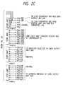
- Fig. 2 shows an arrangement of the controller 500.
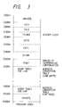
- the controller 500 comprises a CPU (microprocessor) 501 for controlling respective units in accordance with a control procedure shown in Fig. 5, a ROM 503 in which various tables shown in Fig. 3 are developed in addition to a program corresponding to the control procedure shown in Fig. 5 to be executed by the CPU 501, and a RAM 505 serving as a work area when the CPU 501 executes the control procedure.
- a CPU microprocessor
- Port units PORT1 to PORT6 can set I/O directions, and respectively have ports P10 to P17, P20 to P27, P30 to P37, P40 to P47, P50 to P57, and P60 to P67.
- a port unit PORT7 serves as an output port, and has ports P70 to P74.
- I/O setting registers (data direction registers) DDR1 to DDR6 switch I/O directions of the port units PORT1 to PORT6.
- the ports P13 to P17 (corresponding to signals A3 to A7) of the port unit PORT1, the ports P21 to P25 and P27 of the port unit PORT2, the ports P40 and P41 (corresponding to signals A8 and A9) of the port unit PORT4, the ports P53 to P57 of the port unit PORT5, the port P62 of the port unit PORT6, the ports P72 to P74 of the port unit PORT7, and terminals MP0, MP1, and STBY of the CPU 501 are unused.
- the controller 500 also comprises a reset unit 507 for resetting the CPU 501, and a clock generator 509 for supplying an operation reference clock (4 MHz) to the CPU 501.
- Timers TMR1, TMR2, and SC1 respectively have reference clock generation sources and registers, and can frequency-divide the reference clock in accordance with setting to the registers.
- the timer TMR2 frequency-divides the reference clock in accordance with setting to the register, and generates the signal Tout serving as a system clock of the data output unit 600.
- the data output unit 600 generates a clock signal for defining one horizontal scanning period (1H) of the display 100 on the basis of the signal Tout.
- the timer TMR1 is used for adjusting an operation time on the program and 1H of the display screen 102, and realizes such adjustment in accordance with a setting value to its register.
- timers TMR1 and TMR2 supply the signal IRQ3 as an internal interrupt signal to the CPU 501 upon time-up of a setting time based on the setting value or at the beginning of the next count operation after time-up, and the CPU 501 accepts this signal as needed.
- timer SCI is not used in this embodiment.
- the controller 500 also includes an internal address bus AB and an internal data bus DB for connecting the CPU 501 and the respective units, and a hand-shake controller 511 connected between the port units PORT5 and PORT6, and the CPU 501.
- Fig. 3 shows memory areas allocated in the ROM 503. Data shown in Table 1 below are developed (stored) in the memory areas.
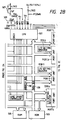
- Fig. 4 shows an arrangement of the data output unit 600.
- a data input unit 601 is linked to the word processor body 1 to receive the signal D and the transfer clock CLK.
- the signal D is a sum signal of the image signal and the horizontal sync signal, and is transmitted from the word processor body 1.
- real address data is superposed on the horizontal sync signal or the horizontal blanking period, and the superposed signal is supplied.
- the data input unit 601 switches a data output path in accordance with the presence/absence of detection of the horizontal sync signal or the horizontal blanking period.
- the data input unit 601 Upon detection of the horizontal sync signal or the horizontal blanking period, the data input unit 601 recognizes the superposed signal component as the real address data, and outputs it as the real address data RA/D.
- the unit 601 recognizes a signal component during this interval as image data, and outputs it as 4-bit parallel image data D0 to D3.
- the data input unit 601 When the data input unit 601 recognizes input of the real address data, it enables the address/data identification signal A/ D .
- the signal A/ D is supplied to an IRQ generator 603 and a DACT generator 605.
- the IRQ generator 603 outputs the interrupt signal IRQ upon reception of the signal A/ D
- the signal IRQ is supplied to the controller 500 as the interrupt instruction IRQ1 in accordance with setting at a switch 520 to perform operation in a line access mode or a block access mode.
- the DACT generator 605 outputs the DACT signal for identifying the presence/absence of access of the display 100 upon reception of the signal A/ D , and supplies it to the controller 500, an FEN generator 611, and a gate array 680.
- the FEN generator 611 generates the signal FEN which starts the gate array 680 in accordance with a trigger signal input from an FEN trigger generator 613 when the DACT signal is enabled.
- the FEN trigger generator 613 generates a trigger signal in response to a write signal ADWR which is output from the controller 500 to cause the A/D converter 950 to fetch temperature information from the thermo sensor 400.
- the FEN trigger generator 613 is selected by the chip select signal DS0 generated by a device selector 621. More specifically, when the controller 500 performs chip selection of the A/D converter 950 to fetch temperature data, the FEN trigger generator 613 is also selected, and frame drive is started in response to the write signal ADWR .
- a busy gate 619 supplies, to the word processor body 1, a signal BUSY for acknowledging a busy state of the display control apparatus 50 in accordance with the busy signal IBUSY from the controller 500.
- the device selector 621 receives the signals A10 to A15 from the controller 500, and outputs the signals DS0 to DS2 for performing chip selection of the A/D converter 950, the D/A converter 900, and the data output unit 600 in accordance with the values of the input signals.
- a register selector 623 is started in response to the signal DS2 , and sets a latch pulse gate array 625 on the basis of the signals A0 to A4 from the controller 500 at that time.
- the latch pulse gate array 625 selects registers in a register unit 630, and consists of bits corresponding in number to the number of registers in the register unit 630.
- the register unit 630 has 22 1-byte areas
- the latch pulse gate array 625 has a 22-bit configuration, each bit of which corresponds to the 1-byte area. More specifically, when the register selector 623 sets bits of the latch pulse gate array 625, the areas corresponding to the set bits are selected, and data read or write access from or to the selected registers is performed through the system data bus in accordance with the read signal RD or the write signal WR supplied from the controller 500 to the latch pulse gate array 625.
- the register unit 630 includes real address data registers RA/DL and RA/DU for respectively storing lower and upper 1-byte data of the real address data RA/D under the control of a real address store controller 641.
- Horizontal dot count data registers DCL and DCU respectively store lower and upper 1-byte data of data corresponding to the number of dots (800 dots in this embodiment) in the horizontal scanning direction of the display.
- a counter 643 for horizontal dot number is started at the beginning of transfer of the image data D0 to D3 to counts clocks. When the counter 643 counts the clocks corresponding to the numerical values stored in the registers DCL and DCU, it causes an LATH generator 645 to generate the latch signal LATH .
- a drive mode register DM stores mode data corresponding to the line or block access mode.
- Registers DLL and DLU store common line selection address data. Data stored in the register DLL is output as address data CA6 and CA5 for designating a block, and address data CA4 to CA0 for designating a line. Data stored in the register DLU is supplied to a decoder 650 to be output as the chip select signals CS0 to CS7 for selecting a common driving element 310.
- One-byte areas CL1 and CL2 store drive data to be supplied to the common side driver 300 when common side lines are driven (line write access) in the block access mode.
- 1-byte areas SL1 and SL2 similarly store drive data to be supplied to the segment side driver 200.
- One-byte areas CB1 and CB2 store drive data to be supplied to the common side driver 300 when common side lines are driven upon block erasure in the block access mode.
- 1-byte areas SB1 and SB2 similarly store drive data to be supplied to the segment side driver 200.
- One-byte areas CC1 and CC2 store data to be supplied to the common side driver 300 when common side lines are driven upon line write access in the line access mode.
- 1-byte areas SC1 and SC2 similarly store drive data to be supplied to the segment side driver 200.
- the following three 1-byte areas are areas for storing data for switching the frame driver 700, and are divided in units of 4 bits, so that registers FV1, FCVc, FV2, FV3, FSVc, and FV4 are allocated.
- a multiplier 661 multiplies, e.g., doubles, the pulse signal Tout from the controller 500.
- Ring counters 663A, 663B, 663C, and 663D respectively count 3-, 4-, 6-, and 12-phase outputs of the multiplier 661, and are respectively used for dividing one horizontal scanning period (1H) by 4, 3, 2, and 1.
- the divided period will be referred to as ⁇ T hereinafter. For example, when the 1H is divided by 3, 3 ⁇ T defines the 1H.
- a multiplexer 665 selects one of the outputs from the ring counters 663A to 663D, and is set in accordance with the content of the drive mode register DM, i.e., data indicating the number of divisions of the 1H. For example, if the number of divisions is 3, the multiplexer 665 selects the output from the 4-phase ring counter 663B.
- a 4-phase ring counter 667 counts the outputs from the ring counters 663A to 663D.
- a multiplexer 669 is set in the same manner as the multiplexer 665.
- Fig. 6 shows the clock Tout, the output waveform of the multiplexer 661, and the output waveforms of the ring counters 663A to 663D and 667. More specifically, when the multiplexer 665 selects one of the outputs from the ring counters 663A to 663D, one of 4 ⁇ T/1H, 3 ⁇ T/1H, 2 ⁇ T/1H, and ⁇ T/1H is selected, and its output waveform is supplied to a shift register unit 673 as a shift clock, thus outputting ON/OFF data for every ⁇ T. One of the outputs from the 4-phase ring counter 667 is selected by the multiplexer 669, and its output waveform is supplied to the shift register unit 673 as a shift/load signal, thus setting an operation based on the selected number of divisions.
- the areas CL1, CB1, and CC1 of the register unit 630 store ON/OFF data for every ⁇ T of the clear signal CCLR and the enable signal CEN to be supplied to the common side driver 300.
- the areas CL2, CB2, and CC2 similarly store ON/OFF data for every ⁇ T of the drive waveform defining signals CM1 and CM2.
- the areas SL1, SB1, and SC1 store ON/OFF state for every ⁇ T of the clear signal SCLR and the enable signal SEN to be supplied to the segment side driver 200.
- the areas SL2, SB2, and SC2 similarly store ON/OFF data for every ⁇ T of the waveform defining signals SM1 and SM2.
- a storage area for each signal data has a 4-bit configuration, and 1 bit corresponds to ON/OFF data of 1 ⁇ T. More specifically, in this embodiment, the maximum number of divisions of 1H is 4.
- a multiplexer unit 671 is linked to the areas CL1 to SC2.
- the multiplexer unit 671 selects one of signal data in line write access and block erasure access in the block access mode and the line write access in the line access mode in accordance with the content of the drive mode register DM.
- the multiplexer unit 671 includes a multiplexer MPX1 for selecting 4-bit data for the signal CCLR from the areas CL1, CB1, and CC1, a multiplexer MPX2 for similarly selecting 4-bit data for the signal CEN, a multiplexer MPX3 for selecting 4-bit data for the signal CM1 from the areas CL2, CB2, and CC2, and a multiplexer MPX4 for similarly selecting 4-bit data for the signal CM2.
- the multiplexer unit 671 also includes a multiplexer MPX5 for selecting 4-bit data for the signal SCLR from the areas SL1, SB1, and SC1, a multiplexer MPX6 for similarly selecting 4-bit data for the signal SEN, a multiplexer MPX7 for selecting 4-bit data for the signal SM1 from the areas SL2, SB2 and SC2, and a multiplexer MPX8 for similarly selecting 4-bit data for the signal SM2.
- a multiplexer MPX5 for selecting 4-bit data for the signal SCLR from the areas SL1, SB1, and SC1
- a multiplexer MPX6 for similarly selecting 4-bit data for the signal SEN
- a multiplexer MPX7 for selecting 4-bit data for the signal SM1 from the areas SL2, SB2 and SC2
- a multiplexer MPX8 for similarly selecting 4-bit data for the signal SM2.
- the shift register unit 673 includes shift registers P/S1 to P/S8 for parallel/serial (P/S) conversion linked to the multiplexers MPX1 to MPX8 of the multiplexer unit 671, respectively.
- the shift register unit 673 receives the output from the multiplexer 665 as a shift clock signal, and defines an output period ⁇ T of the 1-bit ON/OFF data.
- the unit 673 also receives the output from the multiplexer 669 as a preset signal for performing an operation with the preset number of divisions.
- a multiplexer unit 675 includes multiplexers MPX11 to MPX18 linked to the shift registers P/S1 to P/S8, respectively.
- the unit 675 outputs P/S-converted ON/OFF data on the basis of bit selection data (stored in the register DM) of the 4-bit ON/OFF data of the signals stored in the registers CL1 to SC2.
- An output unit 677 performs the same processing as in the shift register unit 673 and the multiplexer unit 675 for the registers FV1, FCVc, FV2, FV3, FSVc, and FV4.
- a gate array 680 is enabled in accordance with the signals DACT and FEN to supply the switch signals V1 to V4 , CVc , and SVc to the frame driver 700.
- An MR generator 690 supplies the signal MR to the controller 500 when the chip select signal DS1 of the D/A converter 900 is enabled, i.e., when the D/A converter 900 is accessed, thereby changing a pulse width of the clock E generated by the CPU 501.
- Fig. 5 shows a program flow of a display control mode. Display control of this embodiment will be briefly described below with reference to Fig. 5.
- step S101 when the power switch of the word processor body 1 is set "ON”, an INIT routine is automatically started (step S101).
- the Busy signal is set to "ON” to perform temperature compensation upon power-on.
- the Busy signal is set to "OFF”, and the control waits until the interrupt request IRQ1 is input (step S102).
- the interrupt request IRQ1 is generated when address data is transferred from the word processor body 1. If no address data is input, the program is not executed, and the display screen 102 is left unchanged.
- control advances to an LSTART routine in accordance with the procedure in step S102.
- the LSTART routine is started, and the corresponding program is executed.
- the transferred address data is loaded from the data output unit 600, and it is checked if this address corresponds to the final line of the effective display region 104 (step S104). If it is determined that the address does not correspond to the final line, program execution branches to an LLINE routine (step S106).
- the Busy signal is set to "ON”, and line write access for one scanning line is performed on the basis of the image data following the address data. Then, the Busy signal is set to "OFF", and the control waits for the interrupt request IRQ1 (step S105).
- the request signal IRQ1 is supplied, the LSTART routine is started again.
- step S105 If it is determined in step S105 that the address data corresponds to the final line, program execution branches to an FLLINE routine. In this routine, line write access of the final line is performed on the basis of the transferred image data. Frame driving and temperature compensation data are then updated, and the Busy signal is set to "OFF" to wait for the interrupt request IRQ1 (step S105). If the interrupt request IRQ1 is input, the LSTART routine is started again. With the above-mentioned procedure, display control in the line access mode is performed.
- display control is performed using three associated counters.
- the three counters are respectively used to determine a frame driving period, an inter-unit correction period, and a temperature compensation period in display control.
- a first counter C1 is a down counter for determining a field driving timing.
- the counter C1 is initialized to a predetermined value in accordance with a temperature, and is decremented by one for each line scanning.
- a field driving operation is performed when the counter value becomes zero, and at that time, the counter is reset.
- the initial value of the counter according to a temperature is set in temperature compensation.
- a second counter C2 is a down counter for determining a timing of inter-unit temperature compensation table correction.
- the counter C2 is initialized to a predetermined value in accordance with a temperature, and is decremented every time the first counter C1 becomes zero, thereby counting the number of field scannings.
- a dip switch for inter-unit correction is read to calculate an offset value for performing temperature compensation table correction.
- a driving condition reflecting the offset value is set. The counter is then reset.
- a third counter C3 is a down counter for determining a temperature compensation timing.
- the counter C3 is initialized to a predetermined value in accordance with a temperature, and is decremented every time the second counter C2 becomes zero, thus counting the number of frame scannings.
- the third counter C3 becomes zero, the output from the temperature sensor is A/D-converted, and the driving condition is set on the basis of this temperature data. The counter is then reset.
- the first and second counters C1 and C2 are set as follows. That is, if the first counter C1 is represented by m and the second counter C2 is represented by n , a product of m and n coincides with the number of scanning lines forming one frame.
- the third counter C3 is read from the look-up table shown in Fig. 3 so that even if one scanning selection period changes due to a change in temperature, waveform setting by temperature compensation is performed at almost a constant cycle over the entire operation temperature range of the display. For example, if the following liquid crystal display apparatus is assumed, the number of lines is set as shown in Table 2 below at respective temperatures.
- the control advances to a field driving routine; 8 fields, an inter-unit correction routine; and 625 frames, a temperature compensation routine.
- the control advances to the field driving routine; 16 fields, the inter-unit correction routine; and 107 frames, the temperature compensation routine.
- Fig. 9 shows an arrangement of the frame driver 700.
- the frame driver 700 includes switches 710, 715, 720, 730, 735, and 740 for respectively turning on/off supply paths of the voltage signals V1, VC, V2, V3, VC, and V4. These switches are controlled by the switch signals V1 , CVc , V2 , V3 , SVc , and V4 supplied from the gate array 680 of the data output unit 600 respectively through inverters 711, 716, 721, 731, 736, and 741.
- the switches 710, 715, and 720 are switched in accordance with the contents of the registers FV1, FCVc, and FV2 allocated in the register unit 630 of the data output unit 600, i.e., the states of the signals V1 , CVc , and V2 , so that a waveform signal selectively having a value of V1, VC, or V2 can be applied to a frame transparent electrode 151 parallel to the common line.
- the switches 730, 735, and 740 are switched in accordance with the contents of the registers FV3, FSVc, and FV4, i.e., the states of the signals V3 , SVc , and V4 , so that a waveform signal selectively having a value of V3, VC, or V4 can be applied to a frame transparent electrode 150 parallel to the segment line.
- Inter-unit correction is performed to set a driving condition to a predetermined correction value since a driving condition varies in units of display units due to a variation in a manufacturing process.
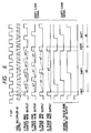
- Figs. 8A to 8E show drive waveforms used in the present invention.
- Fig. 8A shows a scanning selection signal, a scanning nonselection signal, a white information signal, and a black information signal.
- the white information signal is applied from an information electrode to a pixel on a scanning electrode to which the scanning selection signal is applied, the pixel is erased to a black state in a phase T1 (erased to the black state upon application of a voltage V2 in a phase t1 and a voltage of V3 + V2 in a phase t2).
- a voltage of V1 + V3 is applied, and the pixel is written in a white state.
- the pixel is erased to the black state in the phase T1 (erased to the black state upon application of a voltage V2 in a phase t1 and a voltage of -V3 + V2 in a phase t2), and is applied with a voltage of V3 - V1 in the next phase t3, so that the immediately preceding black state is maintained and the pixel is written in the black state.
- the above-mentioned scanning selection signal is applied to every third or more scanning electrodes.
- Fig. 8B exemplifies a case wherein the scanning selection signal is applied to every third scanning electrodes.
- Fig. 8C shows a voltage waveform to be applied to a ferroelectric liquid crystal pixel.
- every third scanning electrodes are selected.
- the present invention is not limited to such an interlace selection method of selecting every third scanning electrodes.
- interlace selection methods of selecting every fourth, fifth, or (N+1)th scanning electrodes may be employed (the number of field scannings at that time is N + 1).
- an interlace selection method of selecting every ninth scanning electrodes is effective to suppress a flicker.
- Figs. 8D and 8E show more preferable examples.
- the scanning selection signal is applied to every seventh scanning electrode. More specifically, the scanning selection signal is applied to 1st (F+1)th, 5th (F+5)th, 3rd (F+3)th, 7th (F+7)th, 2nd (F+2)th, 6th (F+6)th, and 4th (F+4)th scanning electrodes in the order of 1st, 2nd,..., 7th fields (the number of field scannings is represented by F). That is, the application order of scanning signals does not coincide with the order of lines in correspondence with the field order.
- the scanning selection signal is applied to non-adjacent scanning electrodes in continuous seven fields constituting one frame scanning.
- Fig. 8E shows another example (interlace selection method of selecting every fourth electrodes).
- the drive examples shown in Figs. 8D and 8E are more effective in terms of flicker suppression than in a case of the scanning signal application method shown in Fig. 8B.
- ferroelectric liquid crystal elements can be employed. More specifically, an SSFLC disclosed in U.S. Patent US-A-4,367,924 (Clark et al.), a ferroelectric liquid crystal element in an orientation state having a helical residue disclosed in U.S. Patent No. 4,586,791 (Isogai et al.), or a ferroelectric liquid crystal element disclosed in UK Patent Application No. 2,159,635 may be used.
Applications Claiming Priority (2)
| Application Number | Priority Date | Filing Date | Title |
|---|---|---|---|
| JP63274016A JP2632974B2 (ja) | 1988-10-28 | 1988-10-28 | 駆動装置及び液晶装置 |
| JP274016/88 | 1988-10-28 |
Publications (3)
| Publication Number | Publication Date |
|---|---|
| EP0366153A2 EP0366153A2 (en) | 1990-05-02 |
| EP0366153A3 EP0366153A3 (en) | 1991-05-08 |
| EP0366153B1 true EP0366153B1 (en) | 1995-05-31 |
Family
ID=17535786
Family Applications (1)
| Application Number | Title | Priority Date | Filing Date |
|---|---|---|---|
| EP89120038A Expired - Lifetime EP0366153B1 (en) | 1988-10-28 | 1989-10-27 | Liquid crystal apparatus |
Country Status (8)
| Country | Link |
|---|---|
| US (2) | US5506600A (ja) |
| EP (1) | EP0366153B1 (ja) |
| JP (1) | JP2632974B2 (ja) |
| KR (1) | KR940002288B1 (ja) |
| AT (1) | ATE123351T1 (ja) |
| AU (1) | AU627512B2 (ja) |
| DE (1) | DE68922892T2 (ja) |
| ES (1) | ES2072882T3 (ja) |
Families Citing this family (15)
| Publication number | Priority date | Publication date | Assignee | Title |
|---|---|---|---|---|
| JP2632974B2 (ja) * | 1988-10-28 | 1997-07-23 | キヤノン株式会社 | 駆動装置及び液晶装置 |
| JP2584871B2 (ja) * | 1989-08-31 | 1997-02-26 | キヤノン株式会社 | 表示装置 |
| US5757352A (en) * | 1990-06-18 | 1998-05-26 | Canon Kabushiki Kaisha | Image information control apparatus and display device |
| JPH04371998A (ja) * | 1991-06-21 | 1992-12-24 | Canon Inc | 駆動装置 |
| JP2942092B2 (ja) * | 1993-04-20 | 1999-08-30 | キヤノン株式会社 | 液晶素子の制御方法 |
| US6115021A (en) * | 1994-07-04 | 2000-09-05 | Sharp Kabushiki Kaisha | Method and apparatus for driving a liquid crystal panel using a ferroelectric liquid crystal material having a negative dielectric anisotropy |
| US5751257A (en) | 1995-04-28 | 1998-05-12 | Teletransactions, Inc. | Programmable shelf tag and method for changing and updating shelf tag information |
| US6269342B1 (en) | 1995-04-28 | 2001-07-31 | Telxon Corporation | Programmable shelf tag system |
| US5699074A (en) * | 1995-03-24 | 1997-12-16 | Teletransaction, Inc. | Addressing device and method for rapid video response in a bistable liquid crystal display |
| JPH10319896A (ja) * | 1997-05-15 | 1998-12-04 | Sony Corp | 情報表示装置、ならびにその表示状態検出方法、表示状態調整方法、および保守管理方法 |
| JP3281298B2 (ja) * | 1997-09-22 | 2002-05-13 | シャープ株式会社 | 液晶表示素子の駆動装置 |
| US6297816B1 (en) | 1998-05-22 | 2001-10-02 | Hitachi, Ltd. | Video signal display system |
| JP4014895B2 (ja) * | 2001-11-28 | 2007-11-28 | 東芝松下ディスプレイテクノロジー株式会社 | 表示装置およびその駆動方法 |
| US20070016460A1 (en) * | 2005-07-14 | 2007-01-18 | Vocollect, Inc. | Task management system having selectively variable check data |
| CN101546528B (zh) * | 2008-03-28 | 2011-05-18 | 群康科技(深圳)有限公司 | 液晶显示装置及其驱动方法 |
Family Cites Families (23)
| Publication number | Priority date | Publication date | Assignee | Title |
|---|---|---|---|---|
| US4367924A (en) * | 1980-01-08 | 1983-01-11 | Clark Noel A | Chiral smectic C or H liquid crystal electro-optical device |
| US4462027A (en) * | 1980-02-15 | 1984-07-24 | Texas Instruments Incorporated | System and method for improving the multiplexing capability of a liquid crystal display and providing temperature compensation therefor |
| JPS58173718A (ja) * | 1982-04-07 | 1983-10-12 | Hitachi Ltd | 液晶光変調素子およびその製造方法 |
| JPS59129837A (ja) * | 1983-01-14 | 1984-07-26 | Canon Inc | 時分割電圧印加方法及び装置 |
| US4655561A (en) * | 1983-04-19 | 1987-04-07 | Canon Kabushiki Kaisha | Method of driving optical modulation device using ferroelectric liquid crystal |
| AU584867B2 (en) * | 1983-12-09 | 1989-06-08 | Seiko Instruments & Electronics Ltd. | A liquid crystal display device |
| US4701799A (en) * | 1984-03-13 | 1987-10-20 | Sharp Kabushiki Kaisha | Image display panel drive |
| US4712872A (en) * | 1984-03-26 | 1987-12-15 | Canon Kabushiki Kaisha | Liquid crystal device |
| JPS60220316A (ja) * | 1984-04-16 | 1985-11-05 | Canon Inc | 液晶光学素子 |
| US4697887A (en) * | 1984-04-28 | 1987-10-06 | Canon Kabushiki Kaisha | Liquid crystal device and method for driving the same using ferroelectric liquid crystal and FET's |
| GB8413830D0 (en) * | 1984-05-31 | 1984-07-04 | Seltronix Ltd | Blood glucose monitor |
| US4709995A (en) * | 1984-08-18 | 1987-12-01 | Canon Kabushiki Kaisha | Ferroelectric display panel and driving method therefor to achieve gray scale |
| US4923285A (en) * | 1985-04-22 | 1990-05-08 | Canon Kabushiki Kaisha | Drive apparatus having a temperature detector |
| FR2581209B1 (fr) * | 1985-04-26 | 1993-11-05 | Canon Kk | Dispositif optique a cristal liquide |
| JP2576969B2 (ja) * | 1985-11-05 | 1997-01-29 | 株式会社日立製作所 | 液晶表示装置 |
| JPH06101830B2 (ja) * | 1986-03-24 | 1994-12-12 | 日本電信電話株式会社 | 画像表示方式 |
| US5051739A (en) * | 1986-05-13 | 1991-09-24 | Sanyo Electric Co., Ltd. | Driving circuit for an image display apparatus with improved yield and performance |
| US4952032A (en) * | 1987-03-31 | 1990-08-28 | Canon Kabushiki Kaisha | Display device |
| JP2612267B2 (ja) * | 1987-03-31 | 1997-05-21 | キヤノン株式会社 | 表示制御装置 |
| JP2738681B2 (ja) * | 1987-03-31 | 1998-04-08 | キヤノン株式会社 | 表示制御装置 |
| CA1319767C (en) * | 1987-11-26 | 1993-06-29 | Canon Kabushiki Kaisha | Display apparatus |
| JP2632974B2 (ja) * | 1988-10-28 | 1997-07-23 | キヤノン株式会社 | 駆動装置及び液晶装置 |
| JP2794226B2 (ja) * | 1991-04-15 | 1998-09-03 | キヤノン株式会社 | 強誘電性液晶素子の駆動装置および駆動方法 |
-
1988
- 1988-10-28 JP JP63274016A patent/JP2632974B2/ja not_active Expired - Fee Related
-
1989
- 1989-10-27 DE DE68922892T patent/DE68922892T2/de not_active Expired - Fee Related
- 1989-10-27 EP EP89120038A patent/EP0366153B1/en not_active Expired - Lifetime
- 1989-10-27 AU AU43886/89A patent/AU627512B2/en not_active Ceased
- 1989-10-27 AT AT89120038T patent/ATE123351T1/de not_active IP Right Cessation
- 1989-10-27 ES ES89120038T patent/ES2072882T3/es not_active Expired - Lifetime
- 1989-10-28 KR KR1019890015566A patent/KR940002288B1/ko not_active IP Right Cessation
-
1994
- 1994-11-10 US US08/339,299 patent/US5506600A/en not_active Expired - Fee Related
-
1996
- 1996-01-22 US US08/589,456 patent/US5675356A/en not_active Expired - Fee Related
Also Published As
| Publication number | Publication date |
|---|---|
| JPH02120721A (ja) | 1990-05-08 |
| US5675356A (en) | 1997-10-07 |
| ES2072882T3 (es) | 1995-08-01 |
| KR940002288B1 (ko) | 1994-03-21 |
| KR900006904A (ko) | 1990-05-09 |
| EP0366153A2 (en) | 1990-05-02 |
| ATE123351T1 (de) | 1995-06-15 |
| AU4388689A (en) | 1990-05-03 |
| AU627512B2 (en) | 1992-08-27 |
| DE68922892D1 (de) | 1995-07-06 |
| JP2632974B2 (ja) | 1997-07-23 |
| DE68922892T2 (de) | 1995-12-21 |
| US5506600A (en) | 1996-04-09 |
| EP0366153A3 (en) | 1991-05-08 |
Similar Documents
| Publication | Publication Date | Title |
|---|---|---|
| EP0366153B1 (en) | Liquid crystal apparatus | |
| US4964699A (en) | Display device | |
| US4952032A (en) | Display device | |
| US4922241A (en) | Display device for forming a frame on a display when the device operates in a block or line access mode | |
| JP2612267B2 (ja) | 表示制御装置 | |
| US5642128A (en) | Display control device | |
| EP0355693B1 (en) | Display apparatus | |
| US5686934A (en) | Display control apparatus | |
| US5233446A (en) | Display device | |
| US6326943B1 (en) | Display device | |
| JP2670044B2 (ja) | 表示制御装置 | |
| US5248965A (en) | Device for driving liquid crystal display including signal supply during non-display | |
| JP2670045B2 (ja) | 表示制御装置 | |
| JP2738681B2 (ja) | 表示制御装置 | |
| JP3227200B2 (ja) | 表示制御装置及び方法 | |
| EP0452870A2 (en) | Display apparatus and driving circuit | |
| JP2641206B2 (ja) | 表示制御装置 | |
| JP2579934B2 (ja) | 表示制御装置 | |
| JP2554104C (ja) | ||
| JP2575194B2 (ja) | 液晶装置 | |
| JP2738688B2 (ja) | 表示制御装置 | |
| JP2738689B2 (ja) | 表示制御装置 |
Legal Events
| Date | Code | Title | Description |
|---|---|---|---|
| PUAI | Public reference made under article 153(3) epc to a published international application that has entered the european phase |
Free format text: ORIGINAL CODE: 0009012 |
|
| AK | Designated contracting states |
Kind code of ref document: A2 Designated state(s): AT BE CH DE ES FR GB GR IT LI LU NL SE |
|
| 17P | Request for examination filed |
Effective date: 19901221 |
|
| PUAL | Search report despatched |
Free format text: ORIGINAL CODE: 0009013 |
|
| AK | Designated contracting states |
Kind code of ref document: A3 Designated state(s): AT BE CH DE ES FR GB GR IT LI LU NL SE |
|
| 17Q | First examination report despatched |
Effective date: 19930329 |
|
| GRAA | (expected) grant |
Free format text: ORIGINAL CODE: 0009210 |
|
| AK | Designated contracting states |
Kind code of ref document: B1 Designated state(s): AT BE CH DE ES FR GB GR IT LI LU NL SE |
|
| PG25 | Lapsed in a contracting state [announced via postgrant information from national office to epo] |
Ref country code: LI Effective date: 19950531 Ref country code: GR Free format text: LAPSE BECAUSE OF FAILURE TO SUBMIT A TRANSLATION OF THE DESCRIPTION OR TO PAY THE FEE WITHIN THE PRESCRIBED TIME-LIMIT Effective date: 19950531 Ref country code: CH Effective date: 19950531 Ref country code: BE Effective date: 19950531 Ref country code: AT Effective date: 19950531 |
|
| REF | Corresponds to: |
Ref document number: 123351 Country of ref document: AT Date of ref document: 19950615 Kind code of ref document: T |
|
| REF | Corresponds to: |
Ref document number: 68922892 Country of ref document: DE Date of ref document: 19950706 |
|
| REG | Reference to a national code |
Ref country code: ES Ref legal event code: FG2A Ref document number: 2072882 Country of ref document: ES Kind code of ref document: T3 |
|
| ET | Fr: translation filed | ||
| ITF | It: translation for a ep patent filed |
Owner name: SOCIETA' ITALIANA BREVETTI S.P.A. |
|
| REG | Reference to a national code |
Ref country code: CH Ref legal event code: PL |
|
| PG25 | Lapsed in a contracting state [announced via postgrant information from national office to epo] |
Ref country code: LU Free format text: LAPSE BECAUSE OF NON-PAYMENT OF DUE FEES Effective date: 19951031 |
|
| PLBE | No opposition filed within time limit |
Free format text: ORIGINAL CODE: 0009261 |
|
| STAA | Information on the status of an ep patent application or granted ep patent |
Free format text: STATUS: NO OPPOSITION FILED WITHIN TIME LIMIT |
|
| 26N | No opposition filed | ||
| REG | Reference to a national code |
Ref country code: GB Ref legal event code: IF02 |
|
| PGFP | Annual fee paid to national office [announced via postgrant information from national office to epo] |
Ref country code: SE Payment date: 20021004 Year of fee payment: 14 |
|
| PGFP | Annual fee paid to national office [announced via postgrant information from national office to epo] |
Ref country code: FR Payment date: 20021008 Year of fee payment: 14 |
|
| PGFP | Annual fee paid to national office [announced via postgrant information from national office to epo] |
Ref country code: GB Payment date: 20021023 Year of fee payment: 14 |
|
| PGFP | Annual fee paid to national office [announced via postgrant information from national office to epo] |
Ref country code: NL Payment date: 20021031 Year of fee payment: 14 Ref country code: ES Payment date: 20021031 Year of fee payment: 14 Ref country code: DE Payment date: 20021031 Year of fee payment: 14 |
|
| PG25 | Lapsed in a contracting state [announced via postgrant information from national office to epo] |
Ref country code: GB Free format text: LAPSE BECAUSE OF NON-PAYMENT OF DUE FEES Effective date: 20031027 |
|
| PG25 | Lapsed in a contracting state [announced via postgrant information from national office to epo] |
Ref country code: SE Free format text: LAPSE BECAUSE OF NON-PAYMENT OF DUE FEES Effective date: 20031028 Ref country code: ES Free format text: LAPSE BECAUSE OF NON-PAYMENT OF DUE FEES Effective date: 20031028 |
|
| PG25 | Lapsed in a contracting state [announced via postgrant information from national office to epo] |
Ref country code: NL Free format text: LAPSE BECAUSE OF NON-PAYMENT OF DUE FEES Effective date: 20040501 Ref country code: DE Free format text: LAPSE BECAUSE OF NON-PAYMENT OF DUE FEES Effective date: 20040501 |
|
| EUG | Se: european patent has lapsed | ||
| GBPC | Gb: european patent ceased through non-payment of renewal fee |
Effective date: 20031027 |
|
| PG25 | Lapsed in a contracting state [announced via postgrant information from national office to epo] |
Ref country code: FR Free format text: LAPSE BECAUSE OF NON-PAYMENT OF DUE FEES Effective date: 20040630 |
|
| NLV4 | Nl: lapsed or anulled due to non-payment of the annual fee |
Effective date: 20040501 |
|
| REG | Reference to a national code |
Ref country code: FR Ref legal event code: ST |
|
| REG | Reference to a national code |
Ref country code: ES Ref legal event code: FD2A Effective date: 20031028 |
|
| PG25 | Lapsed in a contracting state [announced via postgrant information from national office to epo] |
Ref country code: IT Free format text: LAPSE BECAUSE OF NON-PAYMENT OF DUE FEES Effective date: 20051027 |