EP0366147A2 - Rétroviseur extérieur escamotable pour véhicule automobile - Google Patents
Rétroviseur extérieur escamotable pour véhicule automobile Download PDFInfo
- Publication number
- EP0366147A2 EP0366147A2 EP89120025A EP89120025A EP0366147A2 EP 0366147 A2 EP0366147 A2 EP 0366147A2 EP 89120025 A EP89120025 A EP 89120025A EP 89120025 A EP89120025 A EP 89120025A EP 0366147 A2 EP0366147 A2 EP 0366147A2
- Authority
- EP
- European Patent Office
- Prior art keywords
- mirror
- spring
- detent spring
- mirror housing
- base
- Prior art date
- Legal status (The legal status is an assumption and is not a legal conclusion. Google has not performed a legal analysis and makes no representation as to the accuracy of the status listed.)
- Granted
Links
- 239000011324 bead Substances 0.000 claims description 12
- 210000005069 ears Anatomy 0.000 claims description 5
- 230000000903 blocking effect Effects 0.000 claims 1
- 239000002184 metal Substances 0.000 description 2
- 230000000694 effects Effects 0.000 description 1
- 230000004048 modification Effects 0.000 description 1
- 238000012986 modification Methods 0.000 description 1
- 230000002093 peripheral effect Effects 0.000 description 1
- 230000008719 thickening Effects 0.000 description 1
Images


Classifications
-
- B—PERFORMING OPERATIONS; TRANSPORTING
- B60—VEHICLES IN GENERAL
- B60R—VEHICLES, VEHICLE FITTINGS, OR VEHICLE PARTS, NOT OTHERWISE PROVIDED FOR
- B60R1/00—Optical viewing arrangements; Real-time viewing arrangements for drivers or passengers using optical image capturing systems, e.g. cameras or video systems specially adapted for use in or on vehicles
- B60R1/02—Rear-view mirror arrangements
- B60R1/06—Rear-view mirror arrangements mounted on vehicle exterior
- B60R1/076—Rear-view mirror arrangements mounted on vehicle exterior yieldable to excessive external force and provided with an indexed use position
Definitions
- the invention relates to an exterior mirror for a vehicle with a mirror base that can be fastened to the body of the vehicle, with a mirror housing held on the mirror base with spring force in the position of use, wherein an edge of the mirror housing near the mirror base rests on a shoulder of the mirror base and the mirror housing against its rear edge section in the direction of travel the spring force can be pivoted backwards relative to the mirror base and a locking member is attached to the mirror housing or mirror base and is detachably captured in a pivoted end position in a case formed on the mirror base or mirror housing by a movement of the mirror housing beyond the pivoting end position.
- the driver must push the swivel arm backwards out of the locking position. This can result in a safety risk for the driver insofar as his fingers can be pinched between the front edge of the mirror housing and the mirror base when the mirror housing is folded back into the position of use under the effect of a tension spring which is usually designed to be strong.
- a releasable locking device between the mirror housing and the mirror base is provided to reduce this safety risk, which on the one hand holds the mirror housing in the pivoted end position and on the other hand can be released by a light impact on the outer edge of the mirror housing that the driver is no longer required to intervene with his hands in the opening between the folded mirror housing and mirror base.
- the mirror housing can only be released from the end of the leg position by the application of force in the direction of its position of use. To do this, intervene in the space between the vehicle body and the folded mirror housing.
- a locking mechanism having a spring-loaded rocker in which the folded mirror housing can be released from its swivel end position by the application of force in the direction of the folding movement.
- the latching connection between the locking member and the case is released and changes the relative position of the locking member to the case so that the mirror housing can return to its position of use under the action of the tension springs which are usually attached to it and to the mirror base .
- the present invention has for its object to simplify the design of the locking mechanism known from the last-mentioned utility model.
- the locking member is an elongated detent spring provided transversely to its longitudinal direction with a profile adapted to the trap, and a link deflecting the detent spring is provided, the path of the detent spring defined by the pivoting movement of the mirror housing providing the link or by the pivoting movement of the
- Mirror housing defined path of the backdrop crosses the detent spring such that the catch spring is tensioned in the sense of its release when the profile is trapped in the trap.
- the invention uses the relative stiffness of the detent spring in its longitudinal direction and its soft elasticity transverse to its surface to create a releasable detent mechanism that manages with fewer components than before and without joints and is therefore cheaper with the same functionality and easier to install.
- the detent spring is anchored in a wall of the mirror housing near the mirror base and extends in the position of use in the direction of the mirror base, the latch then being formed on at least one latching ear protruding from the mirror base in the position of use in the mirror housing.
- the profile can consist of an at least one-sided widening of the detent spring and the trap can be formed on the backdrop, which projects into the pivoting path of the widening.
- the trap in the form of a locking shoulder for the widening that blocks the locking spring from pivoting back.
- the link has a cam protruding from its underside at its end remote from the mirror base. So that the detent spring finally finds an unobstructed return to the position of use of the mirror housing after it has been released from the trap, it proves expedient to then keep the top of the backdrop smooth.
- the engagement of the profile in the trap is improved in this embodiment of the invention in that the detent spring is bent at its free end.
- a transverse bead is embossed in the locking spring, the locking ear having a locking seat which has a shape adapted to the bead. It is then advisable to provide on the locking ear a link assigned to the locking seat, which is arranged in the swivel path of a lateral widening at the free end of the locking spring.
- this embodiment of the invention can also be characterized by a further development, according to which the latching ear has two spaced legs connected to the mirror base, which are connected by a latching seat, and each carry a backdrop, which is located in the pivoting path of two opposing, at the end of the Latching spring-formed extensions are arranged and leave a space between them that is larger than the width of a main part of the locking spring and narrower than the width of the locking spring at its end widenings.
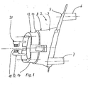
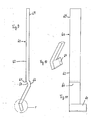
- the exterior mirror consists of a mirror base 2 which can be fastened to a body of a vehicle (not shown), for example the left driver's door of a car, and a mirror housing 4 which is attached to this by means of one or more tension springs.
- the mirror base 2 has a plurality of mounting plates 5 facing inwards protruding mounting pin 6, 7 with which the mirror base can be attached to the vehicle. From the outside of the mounting plate 5 opposite the fastening pin, a round base part 8, provided with a smooth edge contour 3, rises, which merges into a raised base 12 via a circumferential, radially inwardly pointing shoulder 10.
- the base 12 has a circumferential edge 14 which delimits the shoulder 10 inwards and which has a recess 13 in a section which is front with respect to the direction of travel of the vehicle.
- the base is closed off towards the mirror housing by a plate 17, into which the peripheral edge 14 merges and which has an opening 18 communicating with the recess 13.
- a bracket 15 with a through hole 16 in which one end of a tension spring, not shown, is hung either directly or via an intermediate link, the other end of the tension spring being suspended in the mirror housing, for example in the nose 39 fixed to the mirror housing.
- a tension spring not shown
- the line of action 90 of the tension spring is shown in the position of use of the mirror housing.
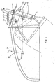
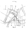
- the position of use is defined in that a circumferential housing edge 19, which is crowned at the free end, on the shoulder 10, the base 12 lies on all sides, as shown in FIG. 2.
- the mirror housing 4 is held by the tension spring, as is known.
- a rear view mirror, not shown, fastened in the mirror housing 4 can then provide the driver with a rearward view.
- the locking tubes 20, 22 are designed symmetrically with respect to a central plane 21 through their space, so that the description of the locking tube 22 applies accordingly to the locking tube 20.
- the locking ear 22 consists of an essentially flat, strong, pointed hat-shaped plate 24, on the upper part of which a curved guide bar 26 protruding from the surface of the plate 24 is formed as a backdrop.
- the guide part 26 On its top 27 facing away from the mirror base, the guide part 26 is smooth and slightly convex with respect to the plate 17.
- the lower side 29 of the guide part 26 opposite the upper side 27 is provided in its lower section with an outwardly projecting latching shoulder 30 as a trap, so that the guide part 26 is thickened in the lower section and tapers downwards from there.
- a sliding cam 28 also protruding from this is formed as a thickening of the guide part 26.
- the locking ear 20 has a guide part 23 as a backdrop with a locking shoulder 25 as a trap on the underside and an upper side 31 corresponding to the upper side 27 (FIG. 2).
- the locking tubes 20, 22 are aligned so that their guide parts 23, 26 extend substantially transversely to a plane in which the mirror housing 4 is pivoted backwards relative to the direction of travel against the force developed by the tension spring from the mirror base 2 can be.
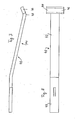
- the mirror housing 4 has in a section which is adjacent to the housing edge 19 and the opening 18 of the plate 17, an inwardly projecting wall 36 in which a detent spring 40 in the form of a profiled narrow sheet metal strip is anchored so that it is secure against pulling and pushing in such a way that the freely movable main part 42 of the detent spring 40 can pass inside the housing edge 19 from the mirror housing 4 into the mirror base 2.
- the detent spring 40 has the property that it is softly elastic transversely to the thickness exaggerated in FIG. 7, that is to say approximately in the direction of the arrow 41, but is practically not elastic in its longitudinal direction.
- the front main part 42 is widened at right angles at the front end on both opposite sides and is bent slightly transversely to its longitudinal extension in a direction which, with the leaf spring 40 installed and in the position of use, points slightly forward on the mirror housing.
- the two opposite widenings of the detent spring 40 are denoted by 44 and 46 and the back of the bend by 48.
- the locking spring 40 installed in the manner described, together with the guide parts 23 and 26, represents a locking mechanism which holds the mirror housing 4 in a rear pivoting end position, which can be released by the force acting on the mirror housing 4 in the direction of pivoting backwards and operates as follows:
- the main part 42 of the detent spring extends through the recess 13 into the hollow interior of the mirror base 2.
- the front housing edge 19 lifts off the associated part of the annular shoulder 10, while the rear section of the housing edge 19 rolls on the back of the ring shoulder 10 against the action of the tension spring.
- the hooks 44 and 46 describe a path corresponding to the relaxed detent spring 40, which traverses the lower part of the guide parts 23 and 26 in the vicinity of the rear pivoting end position.
- the guide parts 23 and 26 are arranged so far crossing the pivoting path of the relaxed detent spring 40 that the lower tip of the guide parts 23, 26 above and the upper end of the upper sides 31, 27 clearly below, each with respect to the plate 17, this way. It can also be seen that the space between the guide parts 23 and 26 is wider than the width of the main part 42 and narrower than the width of the detent spring 40 at their widenings 44, 46.
- the locking mechanism can also be reached with the locking spring 40 and one of the two locking ears 20 or 22, in which case only one of the two hooks 44 or 46 is required.
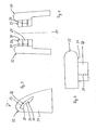
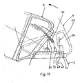
- a detent spring 60 which is cut from a slender, narrow elastic sheet metal strip similar to the detent spring 40, has a section 69 provided for fastening in a mirror housing wall 56 and a main part 62 which is softly elastic in relation to its thickness.
- the free lower end of the detent spring 60 is again bent forward and widened there at right angles to form a hook 64.
- a transverse bead 66 pointing to the kink of the hook 64 is embossed as a profile in the catch spring 60, the concave inside of which is designated by 68.
- the locking spring 60 extends straight from the bead 66 to the hook 64.
- a locking ear 70 is shaped similarly to one of the locking tubes 20 and 22, but instead of the guide parts described above, it has a guide part 76 with a parallelogram cross section as a backdrop and a locking seat 80 as a latch on the side above the guide part 76.
- the detent seat 80 has a round top, the shape of the bead 68 is adapted.
- the locking seat 80 like the guide part 76 and the guide parts 23 and 26, projects transversely from the surface of the locking ear 70.
- the locking ear 70 rises next to the opening 13 or the opening 18 in the base 12 of the mirror base 2 so that the locking seat 80 and the guide member 76 in the pivoting path anchored in the mirror housing wall 56 and with the main part 62 in the position of use of the mirror housing 4 in the Base 12 immersed detent spring 60 or its hook 64 protrudes.
- the detent spring 60 in cooperation with the detent ear 70, forms a detent mechanism which holds the mirror housing 4 in the rear pivoting end position and can be released by further pivoting the mirror housing 4 backwards, so that the mirror housing 4 under the action of the tension spring the position of use can return.
- the main part 62 of the detent spring 60 extends through the opening 18 into the base 12 in the position of use.
- the underside 79 of the guide part 76 engages over the free end section of the main part 62 with hooks 64 and deflects the detent spring 60 to the rear.
- the sharp edge 65 of the bead 68 facing away from the hook 64 can no longer reach the front over the detent seat 80 because the underside 79 catches the hook 64 reaches over and presses the bead 68 onto the rest seat 80.
- the mirror housing 4 can then no longer return to the position of use due to the tension spring, and is therefore in the rear pivoting end position.
- the bead 68 slips from the rest seat 80 with respect to the plate 17 until the hook 64 is released from the underside 79.
- the detent spring 60 relaxes and lifts forward from the detent seat. As shown in FIG.
- the relaxed detent spring 60 has such a distance from both the detent seat 80 and from the guide part 76 that both the hook 64 and the bead 68 move freely over the path Rest seat 80 and the top 77 of the guide member 76 can find away.
- the guide member 76 crosses the swivel path of the hook 64 when the detent spring 60 is relaxed such that the lower edge of the underside 79 is above and the upper edge of the underside 79 is below, in each case with respect to the plate 17, the swivel path of the hook .
- the opening 18 and the opening 13 give the free end of the detent spring 60 enough scope for unimpeded movement without this affecting the guide part 76 or the detent seat 80.
- the catch spring 60 only interacts with a catch ear 70, this can also be the Fig. 13 form can be given.
- the latching ear 70 is supplemented by a part which is symmetrical with respect to the central plane 51, which consequently has a separate guide part 74 with a bottom 73 parallel to the underside 79 and a latching seat 86 passing through the intermediate space between the two guide parts 76, 74.
- the locking ear 71 thus formed stands with the two opposite legs 72 and 75 on the plate 17 of the base 12.
- the locking spring 60 must be supplemented by a hook 64 opposite the center line of the locking spring 60, not shown, which hook then can reach under the bottom 73 when pivoting the mirror housing backwards.
Landscapes
- Engineering & Computer Science (AREA)
- Multimedia (AREA)
- Mechanical Engineering (AREA)
- Rear-View Mirror Devices That Are Mounted On The Exterior Of The Vehicle (AREA)
Priority Applications (1)
| Application Number | Priority Date | Filing Date | Title |
|---|---|---|---|
| AT89120025T ATE91981T1 (de) | 1988-10-27 | 1989-10-27 | Abklappbarer aussenspiegel fuer fahrzeuge. |
Applications Claiming Priority (2)
| Application Number | Priority Date | Filing Date | Title |
|---|---|---|---|
| DE8813505U | 1988-10-27 | ||
| DE8813505U DE8813505U1 (de) | 1988-10-27 | 1988-10-27 | Abklappbarer Außenspiegel für Fahrzeuge |
Publications (3)
| Publication Number | Publication Date |
|---|---|
| EP0366147A2 true EP0366147A2 (fr) | 1990-05-02 |
| EP0366147A3 EP0366147A3 (fr) | 1991-10-02 |
| EP0366147B1 EP0366147B1 (fr) | 1993-07-28 |
Family
ID=6829322
Family Applications (1)
| Application Number | Title | Priority Date | Filing Date |
|---|---|---|---|
| EP89120025A Expired - Lifetime EP0366147B1 (fr) | 1988-10-27 | 1989-10-27 | Rétroviseur extérieur escamotable pour véhicule automobile |
Country Status (4)
| Country | Link |
|---|---|
| EP (1) | EP0366147B1 (fr) |
| AT (1) | ATE91981T1 (fr) |
| DE (3) | DE8813505U1 (fr) |
| ES (1) | ES2042934T3 (fr) |
Families Citing this family (1)
| Publication number | Priority date | Publication date | Assignee | Title |
|---|---|---|---|---|
| BR9802655A (pt) * | 1998-01-22 | 2000-04-25 | Metagal Ind & Comercio | Dispositivo de basculamento e estabilização de espelho retrovisor externo. |
Family Cites Families (3)
| Publication number | Priority date | Publication date | Assignee | Title |
|---|---|---|---|---|
| DE3220893A1 (de) * | 1982-06-03 | 1983-12-08 | Hohe Kg, 6981 Collenberg | Aussenspiegel mit rueckhaltehebel fuer fahrzeuge |
| DE8711959U1 (de) * | 1987-09-03 | 1987-12-23 | Hohe Kg, 6981 Collenberg | Außenspiegel für ein Fahrzeug mit einem Spiegelfuß und einem relativ zum Spiegelfuß aus einer Gebrauchslage nach vorne und hinten abklappbaren Spiegelgehäuse |
| DE8804802U1 (de) * | 1988-04-12 | 1988-09-01 | Hohe Kg, 6981 Collenberg | Abklappbarer Außenspiegel für Fahrzeuge |
-
1988
- 1988-10-27 DE DE8813505U patent/DE8813505U1/de not_active Expired
-
1989
- 1989-10-27 DE DE8912763U patent/DE8912763U1/de not_active Expired - Lifetime
- 1989-10-27 AT AT89120025T patent/ATE91981T1/de not_active IP Right Cessation
- 1989-10-27 DE DE8989120025T patent/DE58905037D1/de not_active Expired - Fee Related
- 1989-10-27 EP EP89120025A patent/EP0366147B1/fr not_active Expired - Lifetime
- 1989-10-27 ES ES89120025T patent/ES2042934T3/es not_active Expired - Lifetime
Also Published As
| Publication number | Publication date |
|---|---|
| ATE91981T1 (de) | 1993-08-15 |
| EP0366147B1 (fr) | 1993-07-28 |
| DE8813505U1 (de) | 1989-03-23 |
| DE58905037D1 (de) | 1993-09-02 |
| ES2042934T3 (es) | 1993-12-16 |
| EP0366147A3 (fr) | 1991-10-02 |
| DE8912763U1 (de) | 1990-03-08 |
Similar Documents
| Publication | Publication Date | Title |
|---|---|---|
| DE69907471T2 (de) | Kraftfahrzeugscheibenwischer | |
| DE2423969C3 (de) | Feststellvorrichtung für längsverschiebbare Fahrzeugsitze | |
| DE3906903C2 (fr) | ||
| DE4424509C2 (de) | Sonnendachvorrichtung für ein Fahrzeug | |
| DE60103816T2 (de) | Schieber für Reissverschluss mit Verriegelungsvorrichtung | |
| DE4320637B4 (de) | Scheibenwischblatt mit einem mehrgliedrigen Tragbügelgestell | |
| DE2940463C2 (de) | Längsverschiebbarer Kraftfahrzeugsitz | |
| DE202005017077U1 (de) | Schiebetüranordnung für ein Kraftfahrzeug | |
| DE2607816B2 (de) | Windabweiseranordnung an einem Kraftfahrzeugdach | |
| DE69403683T2 (de) | Verbindungs-und Gelenkeinrichtung zur Befestigung eines Scheibenwischblatts an einem Wischarm | |
| DE2936051C2 (de) | Hebevorrichtung für ein Kraftfahrzeug-Schiebedach | |
| DE3813049A1 (de) | Gleitschuh, insbesondere fuer fahrzeugschiebedaecher | |
| DE2904616A1 (de) | Vorrichtung zum festhalten der tuer eines kraftfahrzeugs | |
| EP0324926B1 (fr) | Rétroviseur extérieur rabattable pour un véhicule | |
| DE2119209A1 (de) | Schiebetür für das Fahrerhaus von Fahrzeugen | |
| EP0096355B1 (fr) | Pare-chocs pour véhicules automobiles notamment pour une voiture particulière | |
| DE2653106C2 (de) | Klappenhalter | |
| EP1834544A1 (fr) | Verrouillage pour tables de ping-pong dotée de demi-panneaux pivotants | |
| DE69100036T2 (de) | Beschlag fuer einen fensterfluegel eines kippfensters mit verbesserter schliessung. | |
| EP0337364A2 (fr) | Rétroviseur extérieur rabattable pour véhicules | |
| EP0366147B1 (fr) | Rétroviseur extérieur escamotable pour véhicule automobile | |
| EP0367274A2 (fr) | Guidage à glissière double simplifié | |
| DE19719644C2 (de) | Windabweiseranordnung für ein Fahrzeugdach | |
| DE1805420C3 (de) | Türbefestigungseinrichtung | |
| DE2758974C3 (de) | Scharnier |
Legal Events
| Date | Code | Title | Description |
|---|---|---|---|
| PUAI | Public reference made under article 153(3) epc to a published international application that has entered the european phase |
Free format text: ORIGINAL CODE: 0009012 |
|
| AK | Designated contracting states |
Kind code of ref document: A2 Designated state(s): AT BE CH DE ES FR GB IT LI LU NL SE |
|
| PUAL | Search report despatched |
Free format text: ORIGINAL CODE: 0009013 |
|
| AK | Designated contracting states |
Kind code of ref document: A3 Designated state(s): AT BE CH DE ES FR GB IT LI LU NL SE |
|
| 17P | Request for examination filed |
Effective date: 19920324 |
|
| 17Q | First examination report despatched |
Effective date: 19930111 |
|
| GRAA | (expected) grant |
Free format text: ORIGINAL CODE: 0009210 |
|
| AK | Designated contracting states |
Kind code of ref document: B1 Designated state(s): AT BE CH DE ES FR GB IT LI LU NL SE |
|
| REF | Corresponds to: |
Ref document number: 91981 Country of ref document: AT Date of ref document: 19930815 Kind code of ref document: T |
|
| REF | Corresponds to: |
Ref document number: 58905037 Country of ref document: DE Date of ref document: 19930902 |
|
| GBT | Gb: translation of ep patent filed (gb section 77(6)(a)/1977) |
Effective date: 19930810 |
|
| ITF | It: translation for a ep patent filed | ||
| ET | Fr: translation filed | ||
| EPTA | Lu: last paid annual fee | ||
| REG | Reference to a national code |
Ref country code: ES Ref legal event code: FG2A Ref document number: 2042934 Country of ref document: ES Kind code of ref document: T3 |
|
| PLBE | No opposition filed within time limit |
Free format text: ORIGINAL CODE: 0009261 |
|
| STAA | Information on the status of an ep patent application or granted ep patent |
Free format text: STATUS: NO OPPOSITION FILED WITHIN TIME LIMIT |
|
| 26N | No opposition filed | ||
| PGFP | Annual fee paid to national office [announced via postgrant information from national office to epo] |
Ref country code: DE Payment date: 19940929 Year of fee payment: 6 |
|
| PGFP | Annual fee paid to national office [announced via postgrant information from national office to epo] |
Ref country code: LU Payment date: 19941001 Year of fee payment: 6 |
|
| PGFP | Annual fee paid to national office [announced via postgrant information from national office to epo] |
Ref country code: GB Payment date: 19941010 Year of fee payment: 6 |
|
| PGFP | Annual fee paid to national office [announced via postgrant information from national office to epo] |
Ref country code: FR Payment date: 19941017 Year of fee payment: 6 |
|
| PGFP | Annual fee paid to national office [announced via postgrant information from national office to epo] |
Ref country code: AT Payment date: 19941020 Year of fee payment: 6 |
|
| PGFP | Annual fee paid to national office [announced via postgrant information from national office to epo] |
Ref country code: SE Payment date: 19941021 Year of fee payment: 6 |
|
| PGFP | Annual fee paid to national office [announced via postgrant information from national office to epo] |
Ref country code: ES Payment date: 19941025 Year of fee payment: 6 |
|
| PGFP | Annual fee paid to national office [announced via postgrant information from national office to epo] |
Ref country code: NL Payment date: 19941031 Year of fee payment: 6 |
|
| PGFP | Annual fee paid to national office [announced via postgrant information from national office to epo] |
Ref country code: BE Payment date: 19941103 Year of fee payment: 6 |
|
| PGFP | Annual fee paid to national office [announced via postgrant information from national office to epo] |
Ref country code: CH Payment date: 19941121 Year of fee payment: 6 |
|
| EAL | Se: european patent in force in sweden |
Ref document number: 89120025.5 |
|
| PG25 | Lapsed in a contracting state [announced via postgrant information from national office to epo] |
Ref country code: LU Free format text: LAPSE BECAUSE OF NON-PAYMENT OF DUE FEES Effective date: 19951027 Ref country code: GB Effective date: 19951027 Ref country code: AT Effective date: 19951027 |
|
| PG25 | Lapsed in a contracting state [announced via postgrant information from national office to epo] |
Ref country code: SE Effective date: 19951028 Ref country code: ES Free format text: LAPSE BECAUSE OF THE APPLICANT RENOUNCES Effective date: 19951028 |
|
| PG25 | Lapsed in a contracting state [announced via postgrant information from national office to epo] |
Ref country code: LI Effective date: 19951031 Ref country code: CH Effective date: 19951031 Ref country code: BE Effective date: 19951031 |
|
| BERE | Be: lapsed |
Owner name: HOHE K.G. Effective date: 19951031 |
|
| PG25 | Lapsed in a contracting state [announced via postgrant information from national office to epo] |
Ref country code: NL Effective date: 19960501 |
|
| REG | Reference to a national code |
Ref country code: CH Ref legal event code: PL |
|
| GBPC | Gb: european patent ceased through non-payment of renewal fee |
Effective date: 19951027 |
|
| PG25 | Lapsed in a contracting state [announced via postgrant information from national office to epo] |
Ref country code: FR Effective date: 19960628 |
|
| EUG | Se: european patent has lapsed |
Ref document number: 89120025.5 |
|
| PG25 | Lapsed in a contracting state [announced via postgrant information from national office to epo] |
Ref country code: DE Effective date: 19960702 |
|
| NLV4 | Nl: lapsed or anulled due to non-payment of the annual fee |
Effective date: 19960501 |
|
| REG | Reference to a national code |
Ref country code: FR Ref legal event code: ST |
|
| REG | Reference to a national code |
Ref country code: ES Ref legal event code: FD2A Effective date: 19991102 |
|
| PG25 | Lapsed in a contracting state [announced via postgrant information from national office to epo] |
Ref country code: IT Free format text: LAPSE BECAUSE OF NON-PAYMENT OF DUE FEES Effective date: 20051027 |