EP0366053B1 - Vorrichtung zur Herstellung einer Profilschablone - Google Patents
Vorrichtung zur Herstellung einer Profilschablone Download PDFInfo
- Publication number
- EP0366053B1 EP0366053B1 EP89119672A EP89119672A EP0366053B1 EP 0366053 B1 EP0366053 B1 EP 0366053B1 EP 89119672 A EP89119672 A EP 89119672A EP 89119672 A EP89119672 A EP 89119672A EP 0366053 B1 EP0366053 B1 EP 0366053B1
- Authority
- EP
- European Patent Office
- Prior art keywords
- template
- profile
- support
- screen
- grinding
- Prior art date
- Legal status (The legal status is an assumption and is not a legal conclusion. Google has not performed a legal analysis and makes no representation as to the accuracy of the status listed.)
- Expired - Lifetime
Links
Images
Classifications
-
- B—PERFORMING OPERATIONS; TRANSPORTING
- B24—GRINDING; POLISHING
- B24B—MACHINES, DEVICES, OR PROCESSES FOR GRINDING OR POLISHING; DRESSING OR CONDITIONING OF ABRADING SURFACES; FEEDING OF GRINDING, POLISHING, OR LAPPING AGENTS
- B24B17/00—Special adaptations of machines or devices for grinding controlled by patterns, drawings, magnetic tapes or the like; Accessories therefor
- B24B17/04—Special adaptations of machines or devices for grinding controlled by patterns, drawings, magnetic tapes or the like; Accessories therefor involving optical auxiliary means, e.g. optical projection form grinding machines
-
- B—PERFORMING OPERATIONS; TRANSPORTING
- B23—MACHINE TOOLS; METAL-WORKING NOT OTHERWISE PROVIDED FOR
- B23Q—DETAILS, COMPONENTS, OR ACCESSORIES FOR MACHINE TOOLS, e.g. ARRANGEMENTS FOR COPYING OR CONTROLLING; MACHINE TOOLS IN GENERAL CHARACTERISED BY THE CONSTRUCTION OF PARTICULAR DETAILS OR COMPONENTS; COMBINATIONS OR ASSOCIATIONS OF METAL-WORKING MACHINES, NOT DIRECTED TO A PARTICULAR RESULT
- B23Q17/00—Arrangements for observing, indicating or measuring on machine tools
- B23Q17/24—Arrangements for observing, indicating or measuring on machine tools using optics or electromagnetic waves
Definitions
- the invention relates to a device for producing a profile template according to the preamble of claim 1.
- cutter heads are used which are equipped with profile knives with which woods can be profiled.
- profile knives are manufactured according to profile templates, which in turn have to be manufactured according to a pre-made pattern.
- a blank is used to produce the template, which is placed on the template pattern. Then the profile contour of the template pattern is traversed with a grinding wheel and the profile is produced accordingly in the blank.
- the preparation of the template with such a device requires great care, high skill and a lot of experience.
- the profile contour of the template pattern and the profile contour of the profile template to be produced in each case are projected onto the screen of the projector.
- part of the tool is projected onto the screen, with which the profile contour of the profile template is produced.
- the invention has for its object to design the generic device so that stencils can be produced with it exactly, without this requiring the operation of the device experience and skill.
- the contour of the template pattern is preferably projected onto the screen of the projector in a greatly enlarged scale.
- the profile contour of the profile template to be produced is outside the projection path of the projector, so that it does not appear on the screen.
- the marking on the screen corresponds to the grinding wheel of the profile template support.
- the copy support is now set so that the profile contour of the stencil pattern lies on the screen at the marking at the beginning of the profile contour. Since the two supports are firmly connected to each other during the production of the profile template, the setting to be produced is the same with this setting Adjust the template so that the grinding wheel lies at the beginning of the profile contour to be produced.
- the user of the device according to the invention can now very easily adjust the two supports so that the profile contour of the template pattern visible on the screen is guided along the marking.
- This movement is transferred to the profile template support and thus to the profile template to be produced, the profile contour being produced on the profile template.
- the shifting movement can be controlled very easily because of the preferably high magnification, so that the profile template can be manufactured without difficulty even by less experienced forces. Since the profile contour is projected onto the screen, a model as a template pattern is no longer required. It is sufficient if a transparent drawing sheet is used as the template pattern, which shows the profile contour to be produced. This drawing can then, for example, be projected onto the screen of the projector using the transmitted light method.
- the invention is explained in more detail using an exemplary embodiment shown in the drawing.
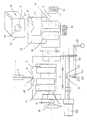
- the drawing shows a schematic representation of a template profiling device according to the invention.
- the template profiling device has a grinding support 1, which is firmly connected to a copy support 2.
- the grinding support 1 carries a grinding mandrel 3 which has a clamping device 4 for the profile template 5 to be ground.
- the profile 6 is ground in a copy-controlled manner using a grinding wheel 7.
- the grinding arbor 3 can be advanced in the direction of arrow 9 on the grinding support 1 against the grinding wheel 7.
- the copy support 2 carries two holders 10, 11 with which two plates 12 made of transparent material, preferably glass, can be held on the copy support 2. Between the plates 12, a transparent drawing sheet 13 is inserted, on which the profile template 5 'to be produced is drawn on a scale of 1: 1. The two plates 12 protrude beyond the copy support 2 that the drawing 5 'is outside the copy support. In order to be able to adjust the holders 10, 11 with the plates 12 in the X and Y directions, two setting wheels 14 and 15 are mounted on the copy support 2.
- the drawing 5 ' shows exactly the profile contour 6', which is to be produced on the profile template 5.
- the template profiling device also has a projector 16 with a screen 17. It bears a circular marking 18, the radius R of which corresponds to the radius r of the grinding wheel jacket 19, multiplied by a magnification factor z. In the exemplary embodiment, the radius R is 20 times the radius r of the grinding wheel jacket 19.
- the profile contour 6 'of the drawing 5' is shown in the sublight method on a scale of z: 1, in the exemplary embodiment 20: 1, on the screen 17 of the projector 16.
- the unit from grinding support 1 and copy support 2 is now moved in the X and Y directions so that the profile contour 6 'of the drawing 5' is guided along the circular marking 18 of the screen 17.
- the circular marking 18 symbolizes the grinding wheel 7.
- the profile template 5 is profiled by the grinding wheel 7 in accordance with the scanned profile contour 6 '.
- the template profiling device is set so that the distance between the grinding wheel 7 and the center of the circular marking 18 is the same as the distance between the profile template 5 and the drawing 5 '.
- the grinding wheel 7 thus profiles when moving the circular marking 18 through the profile contour 6 'in a single process, the template 5 to the desired profile contour 6.
- the profile template 5 according to the drawing 5' can be made on a scale of 1: 1. Since the plates 12 and the drawing sheet 13 are transparent, the drawing sheet 5 'on the screen 17 of the Projector 16 are projected. Instead of the transparent drawing sheet 13, for example, a 1: 1 scale wood sample can also be used. In this case, the contour of this wood pattern is projected onto the screen 17 of the projector 16 using the incident light method. Even then, the profile contour 6 'on the circular marking 18 can easily move.
- a preferably controllable drive motor 20 is provided, which is arranged on the grinding support 1.
- a lever 23 is articulated on the grinding support 1 between two tabs 21, 22, the other end of which is articulated between two tabs 25, 26 projecting perpendicularly from a shaft 24.
- a radially projecting lever 27 is fastened in a rotationally fixed manner, with which the shaft 24 can be rotated about its axis.
- the unit consisting of grinding support 1 and copying support 3 is moved in the X direction by the drive motor 20.
- the drive motor 20 can be regulated, it is possible to move the support unit 1, 2 in the X direction at a somewhat higher speed in the case of less complicated profiles 6, while the travel speed can be reduced in the case of more complicated profiles. Different speeds can be set within a single profile and are particularly advantageous.
- Within a profile 6 Provide areas that can be traversed very quickly and areas that require a slower travel speed in the X direction, such as. B. Steep edges on the profile 6.
- the support unit 1, 2 Since with the drive motor 20, the support unit 1, 2 is constantly moved by the drive motor 20 in the X direction, the user of the stencil profiling means by means of the lever 27, the support unit 1, 2 only in the Y direction move that the circular marking 18 is always exactly on the profile contour 6 'of the drawing 5'.
- the drive motor 20 is not controllable, but rather moves the support unit 1, 2 at a constant, as low as possible speed.
- a major advantage of the template profiling device is that the radius r of the grinding wheel jacket 19 is imaged with the magnification factor z in the projector 16.
- the profile contour 6 'of the drawing 5' is shown with a corresponding magnification factor. If inaccuracies should now occur when the profile contour 6 is traversed, then these inaccuracies have only an insignificant effect on the profile contour 6 to be produced, because there these inaccuracies are smaller by the magnification factor z than on the screen 17.
- the lever 27 is preferably attached to the shaft 24 with a clamp. This makes it possible to adjust the lever 27 relative to the shaft 24 so that it is at the correct height depending on the size of the operator.
- the gear ratio in the Y direction can be set. For example, in one setting the lever 27 has to be pivoted over a larger angular range in order to achieve a specific Y-path, while in another setting of the lever 27 to the shaft 24 a smaller pivoting path is required for the same Y-path. As a result, individual adjustment is possible both with regard to the size of the operator and with regard to their sensitivity or skill.
- the corresponding profile knives are produced in the grinding machine.
- the template profiling device described is preferably part of the grinding machine. However, it is possible to use the template profiling device as an additional device.
- the grinding wheel 7 can of course have a wide variety of profiles depending on the profile 6 of the template 5 to be produced.
- the marking 18 on the screen 17 of the projector 16 is also designed accordingly.
Description
- Die Erfindung betrifft eine Vorrichtung zur Herstellung einer Profilschablone nach dem Oberbegriff des Anspruches 1.
- Beispielsweise bei Holzbearbeitungsmaschinen werden Messerköpfe eingesetzt, die mit Profilmessern bestückt sind, mit denen Hölzer profiliert werden können. Diese Profilmesser werden nach Profilschablonen hergestellt, die ihrerseits nach einem vorgefertigten Muster hergestellt werden müssen. Zur Herstellung der Schablone wird ein Rohling verwendet, der an das Schablonenmuster angelegt wird. Dann wird mit einer Schleifscheibe die Profilkontur des Schablonenmusters abgefahren und hierbei entsprechend das Profil im Rohling hergestellt. Die Herstellung der Schablone mit einer solchen Vorrichtung erfordert große Sorgfalt, hohe Geschicklichkeit und viel Erfahrung.
- Bei der gattungsgemäßen Vorrichtung (US-A-2 887 827) werden in den Bildschirm des Projektors die Profilkontur des Schablonenmusters und die Profilkontur der jeweils herzustellenden Profilschablone projiziert. Außerdem wird in den Bildschirm ein Teil des Werkzeuges projiziert, mit dem die Profilkontur der Profilschablone hergestellt wird.
- Der Erfindung liegt die Aufgabe zugrunde, die gattungsgemäße Vorrichtung so auszubilden, daß mit ihr Schablonen genau hergestellt werden können, ohne daß hierzu die Bedienung der Vorrichtung Erfahrung und Geschick erfordert.
- Diese Aufgabe wird bei der gattungsgemäßen Vorrichtung erfindungsgemäß mit den kennzeichnenden Merkmalen des Anspruches 1 gelöst.
- Bei der erfindungsgemäßen Vorrichtung wird ausschließlich die Kontur des Schablonenmusters vorzugsweise in stark vergrößertem Maßstab auf den Bildschirm des Projektors projiziert. Die Profilkontur der herzustellenden Profilschablone befindet sich außerhalb des Projektionsweges der Projektors, so daß sie nicht auf dem Bildschirm erscheint. Dadurch kann sich der Benutzer ausschließlich darauf konzentrieren, mit der Profilkontur des Schablonenmusters exakt die Markierung auf dem Bildschirm abzufahren. Die im Bildschirm befindliche Markierung entspricht der Schleifscheibe des Profilschablonensupports. Der Kopiersupport wird nun so eingestellt, daß die Profilkontur des Schablonenmusters im Bildschirm an der Markierung zu Beginn der Profilkontur anliegt. Da die beiden Supporte während der Herstellung der Profilschablone fest miteinander verbunden sind, wird bei dieser Einstellung in gleichem Maße die herzustellende Schablone so verstellt, daß die Schleifscheibe am Beginn der herzustellenden Profilkontur liegt. Der Benutzer der erfindungsgemäßen Vorrichtung kann nun sehr einfach die beiden Supporte so verstellen, daß die im Bildschirm sichtbare Profilkontur des Schablonenmusters an der Markierung entlang geführt wird. Diese Bewegung wird auf den Profilschablonensupport und damit auf die herzustellende Profilschablone übertragen, wobei die Profilkontur an der Profilschablone hergestellt wird. Auf dem Bildschirm des Projektors läßt sich die Verschiebebewegung wegen der vorzugsweise hohen Vergrößerung sehr einfach kontrollieren, so daß die Profilschablone ohne Schwierigkeiten auch von weniger geübten Kräften genau gefertigt werden kann. Da die Profilkontur auf den Bildschirm projiziert wird, ist ein Modell als Schablonenmuster nicht mehr erforderlich. Es reicht aus, wenn als Schablonenmuster ein transparentes Zeichnungsblatt verwendet wird, das die herzustellende Profilkontur zeigt. Diese Zeichnung kann dann beispielsweise im Durchlichtverfahren auf den Bildschirm des Projektors projiziert werden.
- Weitere vorteilhafte Merkmale ergeben sich aus den weiteren Ansprüchen, der Beschreibung und der Zeichnung.
- Die Erfindung wird anhand eines in der Zeichnung dargestellten Ausführungsbeispieles näher erläutert. Die Zeichnung zeigt in schematischer Darstellung eine erfindungsgemäße Schablonenprofiliereinrichtung.
- Die Schablonenprofiliereinrichtung hat einen Schleifsupport 1, der fest mit einem Kopiersupport 2 verbunden ist. Der Schleifsupport 1 trägt einen Schleifdorn 3, der eine Spannvorrichtung 4 für die zu schleifende Profilschablone 5 aufweist. An ihr wird das Profil 6 mit einer Schleifscheibe 7 kopiergesteuert geschliffen. Der Schleifdorn 3 kann in Pfeilrichtung 9 auf dem Schleifsupport 1 gegen die Schleifscheibe 7 zugestellt werden.
- Der Kopiersupport 2 trägt zwei Halter 10, 11, mit denen zwei aus durchsichtigem Material, vorzugsweise Glas, bestehende Platten 12 auf dem Kopiersupport 2 gehalten werden können. Zwischen die Platten 12 ist ein transparentes Zeichnungsblatt 13 eingelegt, auf dem im Maßstab 1:1 die herzustellende Profilschablone 5′ gezeichnet ist. Die beiden Platten 12 ragen derart über den Kopiersupport 2, daß die Zeichnung 5′ außerhalb des Kopiersupportes liegt. Um die Halter 10, 11 mit den Platten 12 in X- und Y-Richtung verstellen zu können, sind zwei Stellräder 14 und 15 am Kopiersupport 2 gelagert.
- Die Zeichnung 5′ zeigt genau die Profilkontur 6′, die an der Profilschablone 5 hergestellt werden soll.
- Die Schablonenprofiliereinrichtung weist ferner einen Projektor 16 mit einem Bildschirm 17 auf. Er trägt eine Kreismarkierung 18, deren Radius R dem Radius r des Schleifscheibenmantels 19, multipliziert mit einem Vergrößerungsfaktor z, entspricht. Im Ausführungsbeispiel beträgt der Radius R das 20fache des Radius r des Schleifscheibenmantels 19.
- Die Profilkontur 6′ der Zeichnung 5′ wird im Unterlichtverfahren im Maßstab z:1, im Ausführungsbeispiel 20:1, auf dem Bildschirm 17 des Projektors 16 abgebildet. Die Einheit aus Schleifsupport 1 und Kopiersupport 2 wird nun so in X- und in Y-Richtung bewegt, daß die Profilkontur 6′ der Zeichnung 5′ an der Kreismarkierung 18 des Bildschirms 17 entlanggeführt wird. Die Kreismarkierung 18 symbolisiert die Schleifscheibe 7. Beim Abfahren der Kreismarkierung 18 wird die Profilschablone 5 entsprechend der abgetasteten Profilkontur 6′ durch die Schleifscheibe 7 profiliert. Die Schablonenprofiliereinrichtung ist so eingestellt, daß der Abstand zwischen der Schleifscheibe 7 und dem Mittelpunkt der Kreismarkierung 18 gleich ist dem Abstand zwischen der Profilschablone 5 und der Zeichnung 5′. Die Schleifscheibe 7 profiliert somit beim Abfahren der Kreismarkierung 18 durch die Profilkontur 6′ in einem einzigen Verfahrensgang die Schablone 5 auf die gewünschte Profilkontur 6. Mit dieser Einrichtung läßt sich die Profilschablone 5 nach der Zeichnung 5′ im Maßstab 1:1 fertigen. Da die Platten 12 und das Zeichnungsblatt 13 transparent sind, kann im beschriebenen Durchlichtverfahren das Zeichnungsblatt 5′ auf den Bildschirm 17 des Projektors 16 projiziert werden. Anstelle des transparenten Zeichnungsblattes 13 kann beispielsweise auch ein Holzmuster im Maßstab 1:1 verwendet werden. In diesem Falle wird die Kontur dieses Holzmusters im Auflichtverfahren auf den Bildschirm 17 des Projektors 16 projiziert. Auch dann läßt sich die Profilkontur 6′ an der Kreismarkierung 18 leicht abfahren.
- Zum Verstellen des Schleifsupportes 1 und des fest mit ihm verbundenen Kopiersupportes 2 ist ein vorzugsweise regelbarer Antriebsmotor 20 vorgesehen, der am Schleifsupport 1 angeordnet ist. Zur Verstellung in Y-Richtung ist am Schleifsupport 1 zwischen zwei Laschen 21, 22 das eine Ende eines Hebels 23 angelenkt, dessen anderes Ende zwischen zwei senkrecht von einer Welle 24 abstehenden Laschen 25, 26 angelenkt ist. An dem den Laschen 25, 26 gegenüberliegenden Ende ist drehfest ein radial abstehender Hebel 27 befestigt, mit dem die Welle 24 um ihre Achse gedreht werden kann. Beim Schwenken des Hebels 27 wird über die Hebel 23 der Schleifsupport 1 und damit auch der Kopiersupport 2 in Y-Richtung bewegt.
- Während des Profiliervorganges wird die Einheit aus Schleifsupport 1 und Kopiersupport 3 durch den Antriebsmotor 20 in X-Richtung bewegt. Ist der Antriebsmotor 20 regelbar, besteht die Möglichkeit, bei weniger komplizierten Profilen 6 die Supporteinheit 1, 2 mit etwas höherer Geschwindigkeit in X-Richtung zu verfahren, während bei komplizierteren Profilen die Verfahrgeschwindigkeit herabgesetzt werden kann. Die Einstellung unterschiedlicher Geschwindigkeiten ist innerhalb eines einzigen Profiles möglich und besonders vorteilhaft. Es kann innerhalb eines Profiles 6 Bereiche geben, die sehr rasch abgefahren werden können, und Bereiche, die eine langsamere Verfahrgeschwindigkeit in X-Richtung erfordern, wie z. B. Steilkanten am Profil 6. Da mit dem Antriebsmotor 20 die Supporteinheit 1, 2 ständig durch den Antriebsmotor 20 in X-Richtung bewegt wird, muß der Benutzer der Schablonenprofiliereinrichtung mittels des Hebels 27 die Supporteinheit 1, 2 nur noch in Y-Richtung so bewegen, daß die Kreismarkierung 18 stets genau an der Profilkontur 6′ der Zeichnung 5′ anliegt.
- Bei einer einfachen Ausführungsform ist es auch möglich, daß der Antriebsmotor 20 nicht regelbar ist, sondern die Supporteinheit 1, 2 mit einer konstanten, möglichst geringen Geschwindigkeit bewegt.
- Es ist auch möglich, anstelle des Antriebsmotors 20 eine Handverstellung auch in X-Richtung vorzusehen. In diesem Fall muß die Bedienungsperson die Supporteinheit 1, 2 sowohl in X- als auch in Y-Richtung von Hand bewegen.
- Ein wesentlicher Vorteil der Schablonenprofiliereinrichtung besteht darin, daß im Projektor 16 der Radius r des Schleifscheibenmantels 19 mit dem Vergrößerungsfaktor z abgebildet wird. Auch die Profilkontur 6′ der Zeichnung 5′ wird mit einem entsprechenden Vergrößerungsfaktor abgebildet. Wenn nun beim Abfahren der Profilkontur 6′ Ungenauigkeiten auftreten sollten, dann wirken sich diese Ungenauigkeiten bei der herzustellenden Profilkontur 6 nur unwesentlich aus, weil dort diese Ungenauigkeiten um den Vergrößerungsfaktor z geringer ausfallen als am Bildschirm 17.
- Der Hebel 27 ist vorzugweise mit einer Klemme auf der Welle 24 befestigt. Dadurch besteht die Möglichkeit, den Hebel 27 gegenüber der Welle 24 so einzustellen, daß er je nach Größe der Bedienungsperson in der richtigen Höhe liegt. Außerdem kann dadurch das Übersetzungsverhältnis in Y-Richtung eingestellt werden. So muß in der einen Einstellung beispielsweise der Hebel 27 über einen größeren Winkelbereich geschwenkt werden, um einen bestimmten Y-Weg zu erzielen, während bei einer anderen Einstellung des Hebels 27 zur Welle 24 für den gleichen Y-Weg ein geringerer Schwenkweg erforderlich ist. Dadurch ist eine individuelle Anpassung sowohl hinsichtlich der Größe der Bedienungsperson als auch hinsichtlich deren Feinfühligkeit bzw. Geschicklichkeit möglich.
- Mit den hergestellten Schablonen 5 werden in der Schleifmaschine die entsprechenden Profilmesser hergestellt.
- Bevorzugt ist die beschriebene Schablonenprofiliereinrichtung Bestandteil der Schleifmaschine. Es ist aber möglich, die Schablonenprofiliereinrichtung als Zusatzeinrichtung zu verwenden.
- Die Schleifscheibe 7 kann selbstverständlich je nach herzustellendem Profil 6 der Schablone 5 die unterschiedlichsten Profile aufweisen. Entsprechend ist auch die Markierung 18 auf dem Bildschirm 17 des Projektors 16 ausgebildet.
Claims (15)
- Vorrichtung zur Herstellung einer Profilschablone (5), mit einem Halter (4) zur Befestigung der herzustellenden Profilschablone (5), der auf einem Profilschablonensupport (1) vorgesehen ist, der einem Werkzeug (7) zugeordnet und der mit einem Kopiersupport (2) fest verbunden ist, der gemeinsam mit dem Profilschablonensupport (1) bei der Herstellung der Profilschablone (5) verstellbar ist und der ein Schablonenmuster (5') trägt, dessen Profilkontur (6') auf einen Bildschirm (17) eines Projektors (16) projizierbar ist, dadurch gekennzeichnet, daß der Bildschirm (17) des Projektors (16) mit einer Markierung (18) versehen ist, längs der die Profilkontur (6') des Schablonenmusters (5') während der Herstellung der Profilschablone (5) mittels des Kopiersupportes (2) bewegbar ist, und daß die Profilkontur (6) der herzustellenden Profilschablone (5) sowie das als Schleifscheibe (7) ausgebildete Werkzeug außerhalb des Projektionsweges des Projektors (16) liegen.
- Vorrichtung nach Anspruch 1,
dadurch gekennzeichnet, daß das Schablonenmuster (5') eine die herzustellende Schablone (5) vorzugsweise im Maßstab 1:1 zeigende Zeichnung auf einem transparenten Zeichnungsblatt ist. - Vorrichtung nach Anspruch 2,
dadurch gekennzeichnet, daß das transparente Zeichnungsblatt (5') zwischen zwei transparenten, vorzugweise aus Glas bestehenden Platten (12) liegt. - Vorrichtung nach Anspruch 1,
dadurch gekennzeichnet, daß das Schablonemuster ein der herzustellenden Schablone (5) vorzugweise im Maßstab 1:1 entsprechendes Modell, vorzugsweise ein Holzmuster, ist. - Vorrichtung nach einem der Ansprüche 1 bis 4,
dadurch gekennzeichnet, daß die Markierung (18) im Bildschirm (17) eine der Form des Mantels (19) einer Schleifscheibe (7) entsprechende Form hat. - Vorrichtung nach Anspruch 5,
dadurch gekennzeichnet, daß die Form der Markierung (18) um einen Vergrößerungsfaktor (z) größer ist als die Form des Schleifscheibenmantels (19). - Vorrichtung nach einem der Ansprüche 1 bis 6,
dadurch gekennzeichnet, daß die auf den Bildschirm (17) projizierte Profilkontur (6') des Schablonenmusters (5') um einen Vergrößerungsfaktor (z) größer ist als die herzustellende Profilkontur (6) der Schablone (5). - Vorrichtung nach einem der Ansprüche 1 bis 7,
dadurch gekennzeichnet, daß die Einheit aus Schleifsupport (1) und Kopiersupport (2) mit einem vorzugsweise regelbaren Antriebsmotor (20) in X-Richtung bewegbar ist. - Vorrichtung nach einem der Ansprüche 1 bis 8,
dadurch gekennzeichnet, daß zum Verstellen der Einheit aus Schleifsupport (1) und Kopiersupport (2) in Y-Richtung ein Handantrieb (23, 24, 27) vorgesehen ist. - Vorrichtung nach Anspruch 8 oder 9,
dadurch gekennzeichnet, daß der Antriebsmotor (20) am Schleifsupport (1) vorgesehen ist. - Vorrichtung nach Anspruch 9 oder 10,
dadurch gekennzeichnet, daß der Handantrieb (23, 24, 27) am Schleifsupport (1) angeordnet ist. - Vorrichtung nach einem der Ansprüche 9 bis 11,
dadurch gekennzeichnet, daß der Handantrieb eine mit dem Schleifsupport (1) verbundene Welle (24) aufweist, die mit einem Hebel (27) drehbar ist. - Vorrichtung nach Anspruch 12,
dadurch gekennzeichnet, daß die Welle (24) über einen weiteren, quer von ihr abstehenden Hebel (23) mit dem Schleifsupport (1) antriebsverbunden ist. - Vorrichtung nach Anspruch 12 oder 13,
dadurch gekennzeichnet, daß der Hebel (27) auf der Welle (24) verstellbar angeordnet ist. - Vorrichtung nach einem der Ansprüche 1 bis 14,
dadurch gekennzeichnet, daß der Abstand zwischen der Schleifscheibe (7) und der Markierung (18) im Bildschirm (17) gleich dem Abstand zwischen der Schablone (5) und dem Schablonenmuster (5') ist.
Priority Applications (1)
| Application Number | Priority Date | Filing Date | Title |
|---|---|---|---|
| AT89119672T ATE95103T1 (de) | 1988-10-28 | 1989-10-24 | Vorrichtung zur herstellung einer profilschablone. |
Applications Claiming Priority (2)
| Application Number | Priority Date | Filing Date | Title |
|---|---|---|---|
| DE8813579U DE8813579U1 (de) | 1988-10-28 | 1988-10-28 | |
| DE8813579U | 1988-10-28 |
Publications (3)
| Publication Number | Publication Date |
|---|---|
| EP0366053A2 EP0366053A2 (de) | 1990-05-02 |
| EP0366053A3 EP0366053A3 (de) | 1991-03-06 |
| EP0366053B1 true EP0366053B1 (de) | 1993-09-29 |
Family
ID=6829378
Family Applications (1)
| Application Number | Title | Priority Date | Filing Date |
|---|---|---|---|
| EP89119672A Expired - Lifetime EP0366053B1 (de) | 1988-10-28 | 1989-10-24 | Vorrichtung zur Herstellung einer Profilschablone |
Country Status (5)
| Country | Link |
|---|---|
| US (1) | US5155942A (de) |
| EP (1) | EP0366053B1 (de) |
| JP (1) | JPH02279264A (de) |
| AT (1) | ATE95103T1 (de) |
| DE (2) | DE8813579U1 (de) |
Families Citing this family (6)
| Publication number | Priority date | Publication date | Assignee | Title |
|---|---|---|---|---|
| GB2293996B (en) * | 1995-07-20 | 1996-10-23 | Wadkin Public Ltd Co | System for working wood |
| US6852766B1 (en) * | 2000-06-15 | 2005-02-08 | 3M Innovative Properties Company | Multiphoton photosensitization system |
| US6629877B2 (en) * | 2001-02-21 | 2003-10-07 | Leon A. Cerniway | Precision glass grinding |
| US8210411B2 (en) | 2008-09-23 | 2012-07-03 | Ethicon Endo-Surgery, Inc. | Motor-driven surgical cutting instrument |
| CN110509145B (zh) * | 2019-07-10 | 2021-06-25 | 宁波可可磁业股份有限公司 | 一种钕铁硼精密器件的异形磨加工装置 |
| CN111037458A (zh) * | 2019-12-17 | 2020-04-21 | 西安奕斯伟硅片技术有限公司 | 一种监测装置和硅片处理装置 |
Family Cites Families (4)
| Publication number | Priority date | Publication date | Assignee | Title |
|---|---|---|---|---|
| US2397933A (en) * | 1943-02-19 | 1946-04-09 | Linde Air Prod Co | Line tracker control |
| US2887827A (en) * | 1957-09-30 | 1959-05-26 | Optical Gaging Prod Inc | Apparatus for filing templates and the like |
| DE3136241C2 (de) * | 1981-09-12 | 1984-10-31 | Präzisions-Technik GmbH Wertheim, 6980 Wertheim | Verwendung eines mit der Schleifscheibe einer NC-repetiergesteuerten Projektionsformenschleifmaschine verfahrbaren Tastelements und Tastelement für diese Verwendung |
| DE3215188C1 (de) * | 1982-04-23 | 1983-11-17 | Alfred Dipl.-Ing. 6980 Wertheim Kolb | Projektionspult einer optischen Projektions-Formen-Schleifmaschine |
-
1988
- 1988-10-28 DE DE8813579U patent/DE8813579U1/de not_active Expired
-
1989
- 1989-10-24 EP EP89119672A patent/EP0366053B1/de not_active Expired - Lifetime
- 1989-10-24 AT AT89119672T patent/ATE95103T1/de not_active IP Right Cessation
- 1989-10-24 DE DE89119672T patent/DE58905763D1/de not_active Expired - Fee Related
- 1989-10-27 US US07/428,493 patent/US5155942A/en not_active Expired - Fee Related
- 1989-10-27 JP JP1278740A patent/JPH02279264A/ja active Pending
Also Published As
| Publication number | Publication date |
|---|---|
| DE8813579U1 (de) | 1988-12-22 |
| EP0366053A2 (de) | 1990-05-02 |
| US5155942A (en) | 1992-10-20 |
| JPH02279264A (ja) | 1990-11-15 |
| EP0366053A3 (de) | 1991-03-06 |
| DE58905763D1 (de) | 1993-11-04 |
| ATE95103T1 (de) | 1993-10-15 |
Similar Documents
| Publication | Publication Date | Title |
|---|---|---|
| DE2420139C3 (de) | Verfahren und Vorrichtung zur Herstellung einer Wasserzeichenprageform | |
| EP0810088A2 (de) | Vorrichtung zum Bearbeiten von Hohlzylindern | |
| DE3202362A1 (de) | Vorrichtung zum anschleifen, insbesondere zum ausspitzen eines wendelbohrers | |
| EP0366053B1 (de) | Vorrichtung zur Herstellung einer Profilschablone | |
| DE3218492C2 (de) | Maschine zum Herstellen von Kopierschablonen zum Randschleifen von Brillengläsern | |
| DE3338240A1 (de) | Vorrichtung zum bearbeiten der kanten von glastafeln | |
| DE1752718B2 (de) | Maschine zum automatischen Schärfen von Räumwerkzeugen | |
| DE2045244B2 (de) | fräsmaschine zum Einfräsen von Ausnehmungen in Profilstücke für Türoder Fensterrahmen | |
| DE1091835B (de) | Verfahren und Vorrichtung zum Erzeugen von Gegenstaenden mit unregelmaessigen Oberflaechen | |
| DE3110624C2 (de) | Vorrichtung zum Herstellen einer Kontaktlinse | |
| DE3935356A1 (de) | Vorrichtung zur herstellung einer profilschablone | |
| DE514551C (de) | Schneid- oder Schweissmaschine | |
| DE2328439C3 (de) | Schwenkbarer Werkstück-Aufspanntisch für Werkzeugmaschinen, insbesondere für Universal-Fräsmaschinen | |
| DE1929925C3 (de) | Elektrische Kopiersteuerungsvorrichtung für Fräsmaschinen | |
| CH631375A5 (en) | Process and apparatus for profiling a grinding wheel | |
| EP0122456A2 (de) | Verfahren und Vorrichtung zum Bestimmen des Bildausschnitts von Vorlagen für die Reproduktion in der Drucktechnik | |
| DE2751281A1 (de) | Steuervorrichtung fuer schneidbrenner | |
| DE2546284C2 (de) | Kopiervorrichtung für eine Drückmaschine | |
| DE689047C (de) | Verfahren zur Festlegung der Umrissformen von Bauteilen | |
| DE965619C (de) | Vorrichtung zur elektromechanischen Herstellung von Druckformen mit veraenderlichem Reproduktionsmassstab | |
| DE2323737C3 (de) | Vorrichtung zum Gravieren rotationssymmetrischer Werkstücke | |
| EP0124784A2 (de) | Vorrichtung zum Beschriften von Werkstücken | |
| DE2329221C3 (de) | Graviervorrichtung | |
| CH640450A5 (en) | Apparatus for grinding a tool | |
| DE2648013C2 (de) | Verfahren und Vorrichtung zum Positionieren des auf einer Projektionsformenschleifmaschine zu schleifenden oder nachzuschleifenden Profils eines Formstahls |
Legal Events
| Date | Code | Title | Description |
|---|---|---|---|
| PUAI | Public reference made under article 153(3) epc to a published international application that has entered the european phase |
Free format text: ORIGINAL CODE: 0009012 |
|
| AK | Designated contracting states |
Kind code of ref document: A2 Designated state(s): AT BE CH DE ES FR GB GR IT LI LU NL SE |
|
| PUAL | Search report despatched |
Free format text: ORIGINAL CODE: 0009013 |
|
| AK | Designated contracting states |
Kind code of ref document: A3 Designated state(s): AT BE CH DE ES FR GB GR IT LI LU NL SE |
|
| RHK1 | Main classification (correction) |
Ipc: B23Q 17/24 |
|
| 17P | Request for examination filed |
Effective date: 19910905 |
|
| 17Q | First examination report despatched |
Effective date: 19920909 |
|
| GRAA | (expected) grant |
Free format text: ORIGINAL CODE: 0009210 |
|
| AK | Designated contracting states |
Kind code of ref document: B1 Designated state(s): AT BE CH DE ES FR GB GR IT LI LU NL SE |
|
| PG25 | Lapsed in a contracting state [announced via postgrant information from national office to epo] |
Ref country code: SE Effective date: 19930929 Ref country code: NL Effective date: 19930929 Ref country code: GR Free format text: LAPSE BECAUSE OF FAILURE TO SUBMIT A TRANSLATION OF THE DESCRIPTION OR TO PAY THE FEE WITHIN THE PRESCRIBED TIME-LIMIT Effective date: 19930929 Ref country code: ES Free format text: THE PATENT HAS BEEN ANNULLED BY A DECISION OF A NATIONAL AUTHORITY Effective date: 19930929 Ref country code: BE Effective date: 19930929 |
|
| REF | Corresponds to: |
Ref document number: 95103 Country of ref document: AT Date of ref document: 19931015 Kind code of ref document: T |
|
| ET | Fr: translation filed | ||
| PG25 | Lapsed in a contracting state [announced via postgrant information from national office to epo] |
Ref country code: AT Effective date: 19931024 |
|
| PG25 | Lapsed in a contracting state [announced via postgrant information from national office to epo] |
Ref country code: LU Free format text: LAPSE BECAUSE OF NON-PAYMENT OF DUE FEES Effective date: 19931031 Ref country code: LI Effective date: 19931031 Ref country code: CH Effective date: 19931031 |
|
| REF | Corresponds to: |
Ref document number: 58905763 Country of ref document: DE Date of ref document: 19931104 |
|
| ITF | It: translation for a ep patent filed |
Owner name: STUDIO JAUMANN |
|
| GBT | Gb: translation of ep patent filed (gb section 77(6)(a)/1977) |
Effective date: 19940106 |
|
| NLV1 | Nl: lapsed or annulled due to failure to fulfill the requirements of art. 29p and 29m of the patents act | ||
| REG | Reference to a national code |
Ref country code: CH Ref legal event code: PL |
|
| PLBE | No opposition filed within time limit |
Free format text: ORIGINAL CODE: 0009261 |
|
| STAA | Information on the status of an ep patent application or granted ep patent |
Free format text: STATUS: NO OPPOSITION FILED WITHIN TIME LIMIT |
|
| 26N | No opposition filed | ||
| PGFP | Annual fee paid to national office [announced via postgrant information from national office to epo] |
Ref country code: GB Payment date: 19991006 Year of fee payment: 11 |
|
| PGFP | Annual fee paid to national office [announced via postgrant information from national office to epo] |
Ref country code: FR Payment date: 19991020 Year of fee payment: 11 |
|
| PGFP | Annual fee paid to national office [announced via postgrant information from national office to epo] |
Ref country code: DE Payment date: 19991215 Year of fee payment: 11 |
|
| PG25 | Lapsed in a contracting state [announced via postgrant information from national office to epo] |
Ref country code: GB Free format text: LAPSE BECAUSE OF NON-PAYMENT OF DUE FEES Effective date: 20001024 |
|
| GBPC | Gb: european patent ceased through non-payment of renewal fee |
Effective date: 20001024 |
|
| PG25 | Lapsed in a contracting state [announced via postgrant information from national office to epo] |
Ref country code: FR Free format text: LAPSE BECAUSE OF NON-PAYMENT OF DUE FEES Effective date: 20010629 |
|
| PG25 | Lapsed in a contracting state [announced via postgrant information from national office to epo] |
Ref country code: DE Free format text: LAPSE BECAUSE OF NON-PAYMENT OF DUE FEES Effective date: 20010703 |
|
| REG | Reference to a national code |
Ref country code: FR Ref legal event code: ST |
|
| PG25 | Lapsed in a contracting state [announced via postgrant information from national office to epo] |
Ref country code: IT Free format text: LAPSE BECAUSE OF NON-PAYMENT OF DUE FEES Effective date: 20051024 |