EP0364705B1 - Luftförderer für Gasprüfröhrchen - Google Patents
Luftförderer für Gasprüfröhrchen Download PDFInfo
- Publication number
- EP0364705B1 EP0364705B1 EP89116091A EP89116091A EP0364705B1 EP 0364705 B1 EP0364705 B1 EP 0364705B1 EP 89116091 A EP89116091 A EP 89116091A EP 89116091 A EP89116091 A EP 89116091A EP 0364705 B1 EP0364705 B1 EP 0364705B1
- Authority
- EP
- European Patent Office
- Prior art keywords
- bellows
- air conveyor
- conveyor according
- lever
- control stick
- Prior art date
- Legal status (The legal status is an assumption and is not a legal conclusion. Google has not performed a legal analysis and makes no representation as to the accuracy of the status listed.)
- Expired - Lifetime
Links
- 238000005070 sampling Methods 0.000 title claims 5
- 239000007789 gas Substances 0.000 claims description 21
- 238000007789 sealing Methods 0.000 claims description 7
- 238000001514 detection method Methods 0.000 claims description 2
- 230000009191 jumping Effects 0.000 claims description 2
- 244000286663 Ficus elastica Species 0.000 claims 1
- RRHGJUQNOFWUDK-UHFFFAOYSA-N Isoprene Chemical compound CC(=C)C=C RRHGJUQNOFWUDK-UHFFFAOYSA-N 0.000 claims 1
- 239000000463 material Substances 0.000 claims 1
- 229920001195 polyisoprene Polymers 0.000 claims 1
- 238000000034 method Methods 0.000 description 7
- 230000006835 compression Effects 0.000 description 4
- 238000007906 compression Methods 0.000 description 4
- POIUWJQBRNEFGX-XAMSXPGMSA-N cathelicidin Chemical compound C([C@@H](C(=O)N[C@@H](CCCNC(N)=N)C(=O)N[C@@H](CCCCN)C(=O)N[C@@H](CO)C(=O)N[C@@H](CCCCN)C(=O)N[C@@H](CCC(O)=O)C(=O)N[C@@H](CCCCN)C(=O)N[C@@H]([C@@H](C)CC)C(=O)NCC(=O)N[C@@H](CCCCN)C(=O)N[C@@H](CCC(O)=O)C(=O)N[C@@H](CC=1C=CC=CC=1)C(=O)N[C@@H](CCCCN)C(=O)N[C@@H](CCCNC(N)=N)C(=O)N[C@@H]([C@@H](C)CC)C(=O)N[C@@H](C(C)C)C(=O)N[C@@H](CCC(N)=O)C(=O)N[C@@H](CCCNC(N)=N)C(=O)N[C@@H]([C@@H](C)CC)C(=O)N[C@@H](CCCCN)C(=O)N[C@@H](CC(O)=O)C(=O)N[C@@H](CC=1C=CC=CC=1)C(=O)N[C@@H](CC(C)C)C(=O)N[C@@H](CCCNC(N)=N)C(=O)N[C@@H](CC(N)=O)C(=O)N[C@@H](CC(C)C)C(=O)N[C@@H](C(C)C)C(=O)N1[C@@H](CCC1)C(=O)N[C@@H](CCCNC(N)=N)C(=O)N[C@@H]([C@@H](C)O)C(=O)N[C@@H](CCC(O)=O)C(=O)N[C@@H](CO)C(O)=O)NC(=O)[C@H](CC=1C=CC=CC=1)NC(=O)[C@H](CC(O)=O)NC(=O)CNC(=O)[C@H](CC(C)C)NC(=O)[C@@H](N)CC(C)C)C1=CC=CC=C1 POIUWJQBRNEFGX-XAMSXPGMSA-N 0.000 description 3
- 210000002414 leg Anatomy 0.000 description 3
- 239000013013 elastic material Substances 0.000 description 2
- 238000004891 communication Methods 0.000 description 1
- 230000000994 depressogenic effect Effects 0.000 description 1
- 239000012530 fluid Substances 0.000 description 1
- 230000001960 triggered effect Effects 0.000 description 1
- 210000000689 upper leg Anatomy 0.000 description 1
- 238000009423 ventilation Methods 0.000 description 1
- 238000013022 venting Methods 0.000 description 1
Images

Classifications
-
- G—PHYSICS
- G01—MEASURING; TESTING
- G01N—INVESTIGATING OR ANALYSING MATERIALS BY DETERMINING THEIR CHEMICAL OR PHYSICAL PROPERTIES
- G01N1/00—Sampling; Preparing specimens for investigation
- G01N1/02—Devices for withdrawing samples
- G01N1/22—Devices for withdrawing samples in the gaseous state
- G01N1/24—Suction devices
-
- G—PHYSICS
- G01—MEASURING; TESTING
- G01N—INVESTIGATING OR ANALYSING MATERIALS BY DETERMINING THEIR CHEMICAL OR PHYSICAL PROPERTIES
- G01N31/00—Investigating or analysing non-biological materials by the use of the chemical methods specified in the subgroup; Apparatus specially adapted for such methods
- G01N31/22—Investigating or analysing non-biological materials by the use of the chemical methods specified in the subgroup; Apparatus specially adapted for such methods using chemical indicators
- G01N31/223—Investigating or analysing non-biological materials by the use of the chemical methods specified in the subgroup; Apparatus specially adapted for such methods using chemical indicators for investigating presence of specific gases or aerosols
Definitions
- the invention relates to an air conveyor for gas test tubes for the detection of foreign gases or suspended matter in air according to the preamble of claim 1.
- a spring-loaded counting ring is arranged around the device body axis, which unlocks the control rod by rotation to trigger the suction stroke of the bellows (DE 3330578 C2).
- the control rod is locked in the device body for both end positions by means of a radially directed spring-loaded locking cam arranged in the control rod, which, depending on the end position assumed, engages in radial locking recesses in the wall of the device body, with the spring-loaded locking cam for the end position when the bellows is vented a spring-loaded locking element arranged below the counting ring interacts.
- This type of locking of the control rod can disadvantageously result in inaccuracies in determining the start and end of the suction process.
- the invention has for its object to improve an air conveyor of the type mentioned so that a clear definition of the beginning and end of the stroke for the suction process is achieved in order to ensure an accurate reproducible stroke volume.
- the advantages achieved by the invention are in particular that the locking and triggering for the suction element is combined in one assembly, whereby an identical suction characteristic is achieved with each suction stroke, which means that the measuring accuracy is increased.
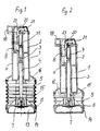
- the air conveyor 1 essentially consists of a device body 2 with a concentrically arranged through channel 3, a control rod 4, which is guided in the through channel 3 in a form-fitting or slidable manner, a suction element designed as a bellows 5, a piston 6, which is firmly connected to the control rod 4 and an air outlet valve 7 arranged on the piston 6, and a locking and triggering device 8 for locking and triggering the control rod 4th
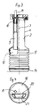
- a so-called gas channel 9 extends over its entire length, which has at one end a sealing insert 10 made of rubber-elastic material for the pluggable reception of a gas test tube 11, and with its other end in connection with the interior 12 the bellows 5 is (see Fig. 3).
- the bellows 5 consists of rubber-elastic material and is flanged with one end to the device body 2 and with its other end to the piston 6 connected to the control rod 4.
- the air outlet valve 7 On the outside of the piston 6 forming a cavity 13, the air outlet valve 7 is arranged, which is in fluid communication with the interior 12 of the bellows 6.
- the air outlet valve 7 serves to blow out the air when the bellows 5 is compressed and is closed during a suction stroke of the bellows 5.
- the cavity 13 of the piston 6 is covered by a cover 14.
- a cylindrical compression spring 15 extends around the control rod 4 within the bellows 5 and is supported on the piston 6 and the end face 16 of the device body 2 opposite it.
- the bellows 5 is circular in cross-section and its diameter corresponds essentially to the diameter of the device body 2 flanged to the bellows 5.
- the device body 2 is above the bellows 5 designed as a handle piece a for gripping with one hand, with a so-called head piece 17 being formed at the end, into which the locking and release device 8 for the control rod 4 is inserted.
- a cap 18 is placed on the head piece 17 so that it cannot be lost, an opening 19 for receiving the gas test tube 11 (see FIGS. 3 and 4) corresponding to the sealing insert 10 and a cutout 20 for receiving a push button 21 being incorporated in the cap 18 ( compare Figure 1, 2 and 4).
- the push button 21 is part of the locking and release device 8.
- the locking and release device 8 consists of an insert piece 22 as a carrier for a locking lever 23 and a pivoting lever 24, both of which interact with the control rod 4 during the process of venting the bellows 5 and trigger and / or lock the control rod 4 from one starting position to the other.
- the angled locking lever 23 is rotatably mounted by means of a bolt 25 in the insert 22 against the force of a spring 26, the leg side protruding from the insert 22 being provided with the pushbutton 21 and the other leg side having a hook 27 projecting outwards.
- the rod-shaped pivot lever 24 is arranged vertically below the locking lever 23 in the direction of its longitudinal axis and rotatably supported with its lower end by means of a bolt 29 in the insert 22 against the force of a spring 30, the pivot lever 24 with its free end in operative contact with the Hook 27 leg side of the locking lever 23 is.
- the pivot lever 24 has a hook 28 projecting outwards from the insert piece 22.
- FIGS. 5, 6 and 7 show the mode of operation of the locking and triggering device 8 with the control rod 4, namely: at the beginning of the suction position (FIG. 5), with the air conveyor 1 being cocked, in a triggering position of the device 8 for implementation of the suction process (FIG. 6) and at the end of the suction position, the air conveyor 1 being relaxed (FIG. 7).
- the bellows In the starting position at the end of a suction process of the air conveyor 1, the bellows is fully ventilated (FIGS. 1, 3 and 7).
- a gas test tube 11 is inserted in the sealing insert 10 (FIG. 3).
- the device body 2 designed as a handle is taken by the operator in one hand and pressed against a firm surface or the thigh of the operator with the cover 14 of the piston 6 with bellows 5 and compression spring 15, whereupon the air in the bellows 5 through the air outlet valve 7 in the cavity 13 escapes and the bellows 5 is vented in this way.
- the device body 2 with the locking and release device 8 moves against the compression spring 15 in the bellows 5 on the control rod 4 sliding in the through-channel 3 until the locking and release device 8 with its spring-loaded hook 27 of the locking lever 23 into the notch 32 the control rod 4 snaps into place and thus fixes the exact end position for the complete ventilation of the bellows 5 and ensures that the suction delivery rate of the air conveyor 1 is always even with each actuation stroke.
- each suction stroke that is carried out must always correspond to the full suction volume of the fully vented bellows 5, so that a precise and reproducible gas volume is sucked through a gas test tube at all times.
- the push button 21 is depressed.
- the locking lever 23 moves with its hook 27 out of the notch 32 of the control rod 4 which is under spring pressure of the compression spring 15, which is thereby unlocked and released and carries out a suction stroke with the bellows 5 and pulls a defined test volume through the attached gas test tube 11.
- the push button is held in the lower position and only released again when the pivot lever 24 engages with its hook 28 at the end of the suction stroke in the recess 32 of the control rod 4 and locks it. By jumping up the spring-loaded button, the end of the suction stroke is suddenly shown and felt.
Landscapes
- Life Sciences & Earth Sciences (AREA)
- Health & Medical Sciences (AREA)
- Chemical & Material Sciences (AREA)
- Biochemistry (AREA)
- Molecular Biology (AREA)
- Physics & Mathematics (AREA)
- Analytical Chemistry (AREA)
- General Health & Medical Sciences (AREA)
- General Physics & Mathematics (AREA)
- Immunology (AREA)
- Pathology (AREA)
- Biomedical Technology (AREA)
- Engineering & Computer Science (AREA)
- Dispersion Chemistry (AREA)
- Biophysics (AREA)
- Sampling And Sample Adjustment (AREA)
Applications Claiming Priority (2)
| Application Number | Priority Date | Filing Date | Title |
|---|---|---|---|
| DE3835885 | 1988-10-21 | ||
| DE3835885A DE3835885C1 (enExample) | 1988-10-21 | 1988-10-21 |
Publications (3)
| Publication Number | Publication Date |
|---|---|
| EP0364705A2 EP0364705A2 (de) | 1990-04-25 |
| EP0364705A3 EP0364705A3 (en) | 1990-12-05 |
| EP0364705B1 true EP0364705B1 (de) | 1993-10-13 |
Family
ID=6365623
Family Applications (1)
| Application Number | Title | Priority Date | Filing Date |
|---|---|---|---|
| EP89116091A Expired - Lifetime EP0364705B1 (de) | 1988-10-21 | 1989-08-31 | Luftförderer für Gasprüfröhrchen |
Country Status (8)
| Country | Link |
|---|---|
| US (1) | US4984476A (enExample) |
| EP (1) | EP0364705B1 (enExample) |
| AU (1) | AU620649B2 (enExample) |
| DE (2) | DE3835885C1 (enExample) |
| ES (1) | ES2045313T3 (enExample) |
| HU (1) | HU209209B (enExample) |
| PL (1) | PL162315B1 (enExample) |
| ZA (1) | ZA897916B (enExample) |
Families Citing this family (6)
| Publication number | Priority date | Publication date | Assignee | Title |
|---|---|---|---|---|
| US5260212A (en) * | 1987-02-09 | 1993-11-09 | Quest International Flavors & Food Ingredients Co., Division Of Indopco | Cloned gene encoding for bacteriocin from Pediococcus acidilactici |
| DE4216404A1 (de) * | 1992-05-18 | 1993-11-25 | Testoterm Mestechnik Gmbh & Co | Gasentnahmevorrichtung für ein Rauchgas-Analysegerät |
| US5437201A (en) * | 1994-03-30 | 1995-08-01 | Shell Oil Company | Negative pressure gas sampling device |
| DE19929777C1 (de) * | 1999-06-29 | 2001-04-19 | Microtape Gmbh | Gasindikator mit einer Nachweissubstanz über die zumindestens zeitweise ein Gasstrom führbar ist |
| CN104122122B (zh) * | 2014-07-31 | 2016-06-29 | 中国环境科学研究院 | 压力稳定采样装置 |
| JP7527729B2 (ja) * | 2020-11-16 | 2024-08-05 | 株式会社ディスコ | 加工装置 |
Family Cites Families (13)
| Publication number | Priority date | Publication date | Assignee | Title |
|---|---|---|---|---|
| BE522197A (enExample) * | 1952-10-14 | |||
| CH440759A (de) * | 1964-10-01 | 1967-07-31 | Ceskoslovenska Akademie Ved | Einrichtung zum Füllen von Proben oder Schutzlösungen in Probegefässe |
| DE1598332C3 (de) * | 1965-08-11 | 1974-02-14 | Draegerwerk Ag, 2400 Luebeck | Gasspürgerät |
| US3422681A (en) * | 1966-06-14 | 1969-01-21 | Atomic Energy Commission | Vehicle actuated roadside air sampling device |
| DE2143282C3 (de) * | 1971-08-30 | 1980-12-04 | Draegerwerk Ag, 2400 Luebeck | Gasspür- bzw. Staubspür- und -meßgerät |
| DE2146248C3 (de) * | 1971-09-16 | 1980-06-26 | Draegerwerk Ag, 2400 Luebeck | Gasspür- bzw. Staubspür- und -meßgerät |
| DE2212363A1 (de) * | 1972-03-15 | 1973-09-20 | Draegerwerk Ag | Gasspuergeraet |
| US3884081A (en) * | 1974-06-24 | 1975-05-20 | California Inst Of Techn | Automated sequential air sampler |
| US4159942A (en) * | 1977-09-22 | 1979-07-03 | Iowa State University Research Foundation, Inc. | Method and apparatus for separating particles |
| SU887995A1 (ru) * | 1980-02-11 | 1981-12-07 | Предприятие П/Я А-3503 | Пробоотборник |
| DE3330578A1 (de) * | 1983-08-22 | 1985-03-14 | Auergesellschaft Gmbh, 1000 Berlin | Luftfoerderer fuer gaspruefroehrchen |
| US4522056A (en) * | 1983-08-26 | 1985-06-11 | Chevron Research Company | Method and apparatus for measuring Reid Vapor Pressure |
| HU195333B (en) * | 1985-05-30 | 1988-04-28 | Zsolt Csillag | Method and device for detecting distrubution of grain size of the grains in suspension |
-
1988
- 1988-10-21 DE DE3835885A patent/DE3835885C1/de not_active Expired
-
1989
- 1989-08-31 DE DE89116091T patent/DE58905903D1/de not_active Expired - Fee Related
- 1989-08-31 ES ES89116091T patent/ES2045313T3/es not_active Expired - Lifetime
- 1989-08-31 EP EP89116091A patent/EP0364705B1/de not_active Expired - Lifetime
- 1989-09-13 HU HU894824A patent/HU209209B/hu not_active IP Right Cessation
- 1989-10-19 US US07/423,937 patent/US4984476A/en not_active Expired - Fee Related
- 1989-10-19 PL PL89281900A patent/PL162315B1/pl unknown
- 1989-10-19 ZA ZA897916A patent/ZA897916B/xx unknown
- 1989-10-20 AU AU43596/89A patent/AU620649B2/en not_active Ceased
Also Published As
| Publication number | Publication date |
|---|---|
| HU209209B (en) | 1994-03-28 |
| EP0364705A2 (de) | 1990-04-25 |
| US4984476A (en) | 1991-01-15 |
| HUT52252A (en) | 1990-06-28 |
| DE58905903D1 (de) | 1993-11-18 |
| ES2045313T3 (es) | 1994-01-16 |
| ZA897916B (en) | 1990-07-25 |
| EP0364705A3 (en) | 1990-12-05 |
| PL162315B1 (pl) | 1993-09-30 |
| AU620649B2 (en) | 1992-02-20 |
| DE3835885C1 (enExample) | 1989-11-16 |
| AU4359689A (en) | 1990-04-26 |
Similar Documents
| Publication | Publication Date | Title |
|---|---|---|
| DE69932155T2 (de) | Vorrichtung zur abgabe einer kühlflüssigkeitsmenge und abgabeeinheit | |
| EP0232489B1 (de) | Austragvorrichtung für fliessfähige Medien | |
| DE2715754B2 (de) | Kürette | |
| DE2012142C3 (de) | Feuerlöscher | |
| DE4031659A1 (de) | Ventilanordnung mit restdruckventil zum fuellen und entleeren eines gasbehaelters | |
| EP0364705B1 (de) | Luftförderer für Gasprüfröhrchen | |
| EP0139862B1 (de) | Luftförderer für Gasprüfröhrchen | |
| EP0499028B1 (de) | Trokarhülse mit Ventil | |
| DE2124485C3 (de) | Hubventil für Schweiß- und Schneidbrenner | |
| DE2705071A1 (de) | Von hand betaetigbare spruehvorrichtung mit automatischer behaelterentlueftung | |
| LU87400A1 (de) | Ventilanordnung zum fuellen und entleeren eines gasbehaelters | |
| WO1992022448A1 (de) | Reifenfüllgerät | |
| EP0282767B1 (de) | Handgerät zum Verändern des Gasdrucks in ventillosen Bällen | |
| EP0079617B1 (de) | Ablassventil für ein Blutdruckmessgerät | |
| DE8904832U1 (de) | Aufblasventil, insbesondere für Aufblasartikel | |
| DE2452495A1 (de) | Spruehkopf fuer einen aerosolbehaelter | |
| DE10005902B4 (de) | Füllanschluß | |
| DE2251308C3 (de) | Vorrichtung zum Steuern der AblaBmenge des Druckmediums aus einem BlutdruckmeBgerät | |
| DE102018117106A1 (de) | Handgerät zur portionierten Ausgabe sprühfähiger Substanzen | |
| DE29911311U1 (de) | Schlauch und Staubsauger mit einem derartigen Schlauch | |
| DE2007607A1 (en) | Hand held semi-automatic pipette filler | |
| DE1755154C (de) | An einen Druckluftschlauch angesetztes Anschlußstück zum Verbinden des Druckluftschlauches mit Ventilen von Kraftfahrzeug-Luftreifen | |
| DE7823134U1 (de) | Ventil fuer schlauchboote, schwimmwesten o.dgl. | |
| DE1233744B (de) | Aufblasvorrichtung fuer ein aufblasbares Rettungsgeraet fuer Flieger | |
| DE2127652B2 (de) | Aerosolzerstäuber |
Legal Events
| Date | Code | Title | Description |
|---|---|---|---|
| PUAI | Public reference made under article 153(3) epc to a published international application that has entered the european phase |
Free format text: ORIGINAL CODE: 0009012 |
|
| 17P | Request for examination filed |
Effective date: 19890908 |
|
| AK | Designated contracting states |
Kind code of ref document: A2 Designated state(s): DE ES FR GB IT NL SE |
|
| PUAL | Search report despatched |
Free format text: ORIGINAL CODE: 0009013 |
|
| AK | Designated contracting states |
Kind code of ref document: A3 Designated state(s): DE ES FR GB IT NL SE |
|
| 17Q | First examination report despatched |
Effective date: 19920723 |
|
| GRAA | (expected) grant |
Free format text: ORIGINAL CODE: 0009210 |
|
| AK | Designated contracting states |
Kind code of ref document: B1 Designated state(s): DE ES FR GB IT NL SE |
|
| ITF | It: translation for a ep patent filed | ||
| REF | Corresponds to: |
Ref document number: 58905903 Country of ref document: DE Date of ref document: 19931118 |
|
| GBT | Gb: translation of ep patent filed (gb section 77(6)(a)/1977) |
Effective date: 19931021 |
|
| REG | Reference to a national code |
Ref country code: ES Ref legal event code: FG2A Ref document number: 2045313 Country of ref document: ES Kind code of ref document: T3 |
|
| ET | Fr: translation filed | ||
| PLBE | No opposition filed within time limit |
Free format text: ORIGINAL CODE: 0009261 |
|
| STAA | Information on the status of an ep patent application or granted ep patent |
Free format text: STATUS: NO OPPOSITION FILED WITHIN TIME LIMIT |
|
| PG25 | Lapsed in a contracting state [announced via postgrant information from national office to epo] |
Ref country code: GB Effective date: 19940831 |
|
| PG25 | Lapsed in a contracting state [announced via postgrant information from national office to epo] |
Ref country code: SE Effective date: 19940901 Ref country code: ES Free format text: LAPSE BECAUSE OF THE APPLICANT RENOUNCES Effective date: 19940901 |
|
| 26N | No opposition filed | ||
| EAL | Se: european patent in force in sweden |
Ref document number: 89116091.3 |
|
| PG25 | Lapsed in a contracting state [announced via postgrant information from national office to epo] |
Ref country code: NL Effective date: 19950301 |
|
| NLV4 | Nl: lapsed or anulled due to non-payment of the annual fee | ||
| GBPC | Gb: european patent ceased through non-payment of renewal fee |
Effective date: 19940831 |
|
| PG25 | Lapsed in a contracting state [announced via postgrant information from national office to epo] |
Ref country code: FR Effective date: 19950428 |
|
| EUG | Se: european patent has lapsed |
Ref document number: 89116091.3 |
|
| REG | Reference to a national code |
Ref country code: FR Ref legal event code: ST |
|
| REG | Reference to a national code |
Ref country code: ES Ref legal event code: FD2A Effective date: 19991007 |
|
| PGFP | Annual fee paid to national office [announced via postgrant information from national office to epo] |
Ref country code: DE Payment date: 20020528 Year of fee payment: 14 |
|
| PG25 | Lapsed in a contracting state [announced via postgrant information from national office to epo] |
Ref country code: DE Free format text: LAPSE BECAUSE OF NON-PAYMENT OF DUE FEES Effective date: 20040302 |
|
| PG25 | Lapsed in a contracting state [announced via postgrant information from national office to epo] |
Ref country code: IT Free format text: LAPSE BECAUSE OF NON-PAYMENT OF DUE FEES;WARNING: LAPSES OF ITALIAN PATENTS WITH EFFECTIVE DATE BEFORE 2007 MAY HAVE OCCURRED AT ANY TIME BEFORE 2007. THE CORRECT EFFECTIVE DATE MAY BE DIFFERENT FROM THE ONE RECORDED. Effective date: 20050831 |