EP0364705B1 - Air transportation device for a gas-sampling tube - Google Patents
Air transportation device for a gas-sampling tube Download PDFInfo
- Publication number
- EP0364705B1 EP0364705B1 EP89116091A EP89116091A EP0364705B1 EP 0364705 B1 EP0364705 B1 EP 0364705B1 EP 89116091 A EP89116091 A EP 89116091A EP 89116091 A EP89116091 A EP 89116091A EP 0364705 B1 EP0364705 B1 EP 0364705B1
- Authority
- EP
- European Patent Office
- Prior art keywords
- bellows
- air conveyor
- conveyor according
- lever
- control stick
- Prior art date
- Legal status (The legal status is an assumption and is not a legal conclusion. Google has not performed a legal analysis and makes no representation as to the accuracy of the status listed.)
- Expired - Lifetime
Links
Images

Classifications
-
- G—PHYSICS
- G01—MEASURING; TESTING
- G01N—INVESTIGATING OR ANALYSING MATERIALS BY DETERMINING THEIR CHEMICAL OR PHYSICAL PROPERTIES
- G01N1/00—Sampling; Preparing specimens for investigation
- G01N1/02—Devices for withdrawing samples
- G01N1/22—Devices for withdrawing samples in the gaseous state
- G01N1/24—Suction devices
-
- G—PHYSICS
- G01—MEASURING; TESTING
- G01N—INVESTIGATING OR ANALYSING MATERIALS BY DETERMINING THEIR CHEMICAL OR PHYSICAL PROPERTIES
- G01N31/00—Investigating or analysing non-biological materials by the use of the chemical methods specified in the subgroup; Apparatus specially adapted for such methods
- G01N31/22—Investigating or analysing non-biological materials by the use of the chemical methods specified in the subgroup; Apparatus specially adapted for such methods using chemical indicators
- G01N31/223—Investigating or analysing non-biological materials by the use of the chemical methods specified in the subgroup; Apparatus specially adapted for such methods using chemical indicators for investigating presence of specific gases or aerosols
Definitions
- the invention relates to an air conveyor for gas test tubes for the detection of foreign gases or suspended matter in air according to the preamble of claim 1.
- a spring-loaded counting ring is arranged around the device body axis, which unlocks the control rod by rotation to trigger the suction stroke of the bellows (DE 3330578 C2).
- the control rod is locked in the device body for both end positions by means of a radially directed spring-loaded locking cam arranged in the control rod, which, depending on the end position assumed, engages in radial locking recesses in the wall of the device body, with the spring-loaded locking cam for the end position when the bellows is vented a spring-loaded locking element arranged below the counting ring interacts.
- This type of locking of the control rod can disadvantageously result in inaccuracies in determining the start and end of the suction process.
- the invention has for its object to improve an air conveyor of the type mentioned so that a clear definition of the beginning and end of the stroke for the suction process is achieved in order to ensure an accurate reproducible stroke volume.
- the advantages achieved by the invention are in particular that the locking and triggering for the suction element is combined in one assembly, whereby an identical suction characteristic is achieved with each suction stroke, which means that the measuring accuracy is increased.
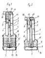
- the air conveyor 1 essentially consists of a device body 2 with a concentrically arranged through channel 3, a control rod 4, which is guided in the through channel 3 in a form-fitting or slidable manner, a suction element designed as a bellows 5, a piston 6, which is firmly connected to the control rod 4 and an air outlet valve 7 arranged on the piston 6, and a locking and triggering device 8 for locking and triggering the control rod 4th
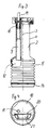
- a so-called gas channel 9 extends over its entire length, which has at one end a sealing insert 10 made of rubber-elastic material for the pluggable reception of a gas test tube 11, and with its other end in connection with the interior 12 the bellows 5 is (see Fig. 3).
- the bellows 5 consists of rubber-elastic material and is flanged with one end to the device body 2 and with its other end to the piston 6 connected to the control rod 4.
- the air outlet valve 7 On the outside of the piston 6 forming a cavity 13, the air outlet valve 7 is arranged, which is in fluid communication with the interior 12 of the bellows 6.
- the air outlet valve 7 serves to blow out the air when the bellows 5 is compressed and is closed during a suction stroke of the bellows 5.
- the cavity 13 of the piston 6 is covered by a cover 14.
- a cylindrical compression spring 15 extends around the control rod 4 within the bellows 5 and is supported on the piston 6 and the end face 16 of the device body 2 opposite it.
- the bellows 5 is circular in cross-section and its diameter corresponds essentially to the diameter of the device body 2 flanged to the bellows 5.
- the device body 2 is above the bellows 5 designed as a handle piece a for gripping with one hand, with a so-called head piece 17 being formed at the end, into which the locking and release device 8 for the control rod 4 is inserted.
- a cap 18 is placed on the head piece 17 so that it cannot be lost, an opening 19 for receiving the gas test tube 11 (see FIGS. 3 and 4) corresponding to the sealing insert 10 and a cutout 20 for receiving a push button 21 being incorporated in the cap 18 ( compare Figure 1, 2 and 4).
- the push button 21 is part of the locking and release device 8.
- the locking and release device 8 consists of an insert piece 22 as a carrier for a locking lever 23 and a pivoting lever 24, both of which interact with the control rod 4 during the process of venting the bellows 5 and trigger and / or lock the control rod 4 from one starting position to the other.
- the angled locking lever 23 is rotatably mounted by means of a bolt 25 in the insert 22 against the force of a spring 26, the leg side protruding from the insert 22 being provided with the pushbutton 21 and the other leg side having a hook 27 projecting outwards.
- the rod-shaped pivot lever 24 is arranged vertically below the locking lever 23 in the direction of its longitudinal axis and rotatably supported with its lower end by means of a bolt 29 in the insert 22 against the force of a spring 30, the pivot lever 24 with its free end in operative contact with the Hook 27 leg side of the locking lever 23 is.
- the pivot lever 24 has a hook 28 projecting outwards from the insert piece 22.
- FIGS. 5, 6 and 7 show the mode of operation of the locking and triggering device 8 with the control rod 4, namely: at the beginning of the suction position (FIG. 5), with the air conveyor 1 being cocked, in a triggering position of the device 8 for implementation of the suction process (FIG. 6) and at the end of the suction position, the air conveyor 1 being relaxed (FIG. 7).
- the bellows In the starting position at the end of a suction process of the air conveyor 1, the bellows is fully ventilated (FIGS. 1, 3 and 7).
- a gas test tube 11 is inserted in the sealing insert 10 (FIG. 3).
- the device body 2 designed as a handle is taken by the operator in one hand and pressed against a firm surface or the thigh of the operator with the cover 14 of the piston 6 with bellows 5 and compression spring 15, whereupon the air in the bellows 5 through the air outlet valve 7 in the cavity 13 escapes and the bellows 5 is vented in this way.
- the device body 2 with the locking and release device 8 moves against the compression spring 15 in the bellows 5 on the control rod 4 sliding in the through-channel 3 until the locking and release device 8 with its spring-loaded hook 27 of the locking lever 23 into the notch 32 the control rod 4 snaps into place and thus fixes the exact end position for the complete ventilation of the bellows 5 and ensures that the suction delivery rate of the air conveyor 1 is always even with each actuation stroke.
- each suction stroke that is carried out must always correspond to the full suction volume of the fully vented bellows 5, so that a precise and reproducible gas volume is sucked through a gas test tube at all times.
- the push button 21 is depressed.
- the locking lever 23 moves with its hook 27 out of the notch 32 of the control rod 4 which is under spring pressure of the compression spring 15, which is thereby unlocked and released and carries out a suction stroke with the bellows 5 and pulls a defined test volume through the attached gas test tube 11.
- the push button is held in the lower position and only released again when the pivot lever 24 engages with its hook 28 at the end of the suction stroke in the recess 32 of the control rod 4 and locks it. By jumping up the spring-loaded button, the end of the suction stroke is suddenly shown and felt.
Description
Die Erfindung betrifft einen Luftförderer für Gasprüfröhrchen zum Nachweis fremder Gase oder Schwebestoffe in Luft nach dem Oberbegriff des Patentanspruches 1.The invention relates to an air conveyor for gas test tubes for the detection of foreign gases or suspended matter in air according to the preamble of claim 1.
Bei einem bekannten Luftförderer dieser Art ist um die Gerätekörperachse ein federbelasteter Zählring angeordnet, der durch eine Drehung die Steuerstange zum Auslösen des Saughubes des Faltenbalges entriegelt (DE 3330578 C2). Hierbei erfolgt die Arretierung der Steuerstange im Gerätekörper für beide Endstellungen mittels eines in der Steuerstange angeordneten und radial gerichteten federbelasteten Sperrnockens, der je nach der eingenommenen Endstellung in radiale Rastausnehmungen in der Wandung des Gerätekörpers einrastet, wobei für die Endstellung bei entlüftetem Faltenbalg der federbelastete Sperrnocken mit einem unterhalb des Zählringes angeordneten federbelasteten Sperrelement zusammenwirkt. Durch diese Art der Arretierung der Steuerstange können sich nachteilig Ungenauigkeiten für die Festlegung von Hubanfang und Hubende des Saugvorganges ergeben.In a known air conveyor of this type, a spring-loaded counting ring is arranged around the device body axis, which unlocks the control rod by rotation to trigger the suction stroke of the bellows (DE 3330578 C2). The control rod is locked in the device body for both end positions by means of a radially directed spring-loaded locking cam arranged in the control rod, which, depending on the end position assumed, engages in radial locking recesses in the wall of the device body, with the spring-loaded locking cam for the end position when the bellows is vented a spring-loaded locking element arranged below the counting ring interacts. This type of locking of the control rod can disadvantageously result in inaccuracies in determining the start and end of the suction process.
Der Erfindung liegt die Aufgabe zugrunde, einen Luftförderer der eingangs genannten Art so zu verbessern, daß eine eindeutige Festlegung von Hubanfang und Hubende für den Saugvorgang erreicht wird, um ein genaues reproduzierbares Hubvolumen zu gewährleisten.The invention has for its object to improve an air conveyor of the type mentioned so that a clear definition of the beginning and end of the stroke for the suction process is achieved in order to ensure an accurate reproducible stroke volume.
Diese Aufgabe wird gemäß der Erfindung bei einem Luftförderer der eingangs genannten Art durch die kennzeichnenden Merkmale des Anspruchs 1 gelöst.This object is achieved according to the invention in an air conveyor of the type mentioned by the characterizing features of claim 1.
Die mit der Erfindung erzielten Vorteile bestehen insbesondere darin, daß die Arretierung und Auslösung für das Saugelement in einer Baugruppe zusammengefaßt ist, wodurch bei jedem Saughub eine gleiche Saugcharakteristik erreicht wird, was bedeutet, daß die Meßgenauigkeit erhöht wird.The advantages achieved by the invention are in particular that the locking and triggering for the suction element is combined in one assembly, whereby an identical suction characteristic is achieved with each suction stroke, which means that the measuring accuracy is increased.
Die Erfindung wird nachstehend anhand eines Ausführungsbeispiels in der Zeichnung dargestellt und im folgenden näher beschrieben.
Es zeigt:
- Fig. 1
- einen Längsschnitt durch einen Luftförderer im belüfteten Zustand des Faltenbalges (der Luftförderer ist enspannt, d.h. am Ende der Saugposition).
- Fig. 2
- einen Längsschnitt durch den Luftförderer im entlüfteten zustand des Faltenbalges (der Luftförderer ist gespannt, d.h. am Anfang der Saugposition).
- Fig. 3
- einen teilweise Längsschnitt durch den Luftförderer im Bereich des Gaskanals.
- Fig. 4
- eine Draufsicht auf den Luftförderer.
- Fig. 5
- eine Darstellung der arretierten Steuerstange des Luftförderers nach Fig. 2 mittels einer erfindungsgemäßen Arretier- und Auslöseeinrichtung am Anfang der Saugposition des Luftförderers.
- Fig. 6
- eine Darstellung der ausgelösten Steuerstange zur Durchführung des Saugvorganges des Luftförderers.
- Fig. 7
- eine Darstellung der arretierten Steuerstange des Luftförderers nach Fig. 1 am Ende der Saugposition, und
- Fig. 8
- einen Schnitt durch die Arretier- und Auslöseeinrichtung.
It shows:
- Fig. 1
- a longitudinal section through an air conveyor in the ventilated state of the bellows (the air conveyor is relaxed, ie at the end of the suction position).
- Fig. 2
- a longitudinal section through the air conveyor in the deflated state of the bellows (the air conveyor is cocked, ie at the beginning of the suction position).
- Fig. 3
- a partial longitudinal section through the air conveyor in the area of the gas duct.
- Fig. 4
- a top view of the air conveyor.
- Fig. 5
- a representation of the locked control rod of the air conveyor according to FIG. 2 by means of a locking and release device according to the invention at the beginning of the suction position of the air conveyor.
- Fig. 6
- a representation of the triggered control rod for performing the suction process of the air conveyor.
- Fig. 7
- a representation of the locked control rod of the air conveyor according to FIG. 1 at the end of the suction position, and
- Fig. 8
- a section through the locking and release device.
Wie aus Fig. 1 ersichtlich ist, besteht der Luftförderer 1 im wesentlichen aus einem Gerätekörper 2 mit einem in diesem konzentrisch angeordneten Durchgangskanal 3, einer Steuerstange 4, die in dem Durchgangskanal 3 formschlüssig bzw. gleitbar geführt wird, einem als Faltenbalg 5 ausgebildeten Saugelement, einem Kolben 6, der mit der Steuerstange 4 fest verbunden ist und einem am Kolben 6 angeordneten Luftauslaßventil 7 sowie einer Arretier- und Auslöseeinrichtung 8 zum Arretieren und Auslösen der Steuerstange 4.1, the air conveyor 1 essentially consists of a
Parallel zum Durchgangskanal 3 und exzentrisch zum Gerätekörper 2 erstreckt sich über dessen gesamte Länge ein sogenannter Gaskanal 9, der an seinem einen Ende einen Dichteinsatz 10 aus gummielastischem Material zur steckbaren Aufnahme eines Gasprüfröhrchens 11 aufweist, und mit seinem anderen Ende in Verbindung mit dem Innenraum 12 des Faltenbalges 5 steht (vergleiche Fig. 3). Auf diese Weise wird das zu untersuchende Gas durch das Gasprüfröhrchen 11 mittels des als Saugelement wirkenden Faltenbalges 5 gesaugt. Der Faltenbalg 5 besteht aus gummielastischem Material und ist mit seinem einen Ende am Gerätekörper 2 und mit seinem anderen Ende an dem mit der Steuerstange 4 verbundenen Kolben 6 festangeflanscht. An der einen Hohlraum 13 bildenden Außenseite des Kolbens 6 ist das Luftauslaßventil 7 angeordnet, welches mit dem Innenraum 12 des Faltenbalges 6 strömungstechnisch in Wirkverbindung steht. Das Luftauslaßventil 7 dient zum Ausblasen der Luft beim Zusammendrücken des Faltenbalges 5 und ist bei einem Saughub des Faltenbalges 5 geschlossen. Der Hohlraum 13 des Kolbens 6 ist von einem Deckel 14 abgedeckt. Um die Steuerstange 4 herum erstreckt sich innerhalb des Faltenbalges 5 eine zylindrische Druckfeder 15, die sich am Kolben 6 und der diesem gegenüberliegenden Stirnfläche 16 des Gerätekörpers 2 abstützt. Der Faltenbalg 5 ist im Querschnitt kreisförmig ausgebildet und sein Durchmesser entspricht im wesentlichen dem Durchmesser der an den Faltenbalg 5 angeflanschten Gerätekörpers 2. Der Gerätekörper 2 ist oberhalb des Faltenbalges 5 als ein Handgriffstück a zum Umfassen mit einer Hand ausgebildet, wobei als Abschluß ein sogenanntes Kopfstück 17 angeformt ist, in das die Arretier- und Auslöseeinrichtung 8 für die Steuerstange 4 eingesetzt ist. Über das Kopfstück 17 ist als Abschluß eine Kappe 18 unverlierbar aufgesetzt, wobei in der Kappe 18 eine mit dem Dichteinsatz 10 korrespondierende Öffnung 19 zur Aufnahme des Gasprüfröhrchens 11 (vergleiche Figur 3 und 4) und ein Ausschnitt 20 zur Aufnahme einer Drucktaste 21 eingearbeitet ist (vergleiche Figur 1, 2 und 4). Die Drucktaste 21 ist Bestandteil der Arretier- und Auslöseeinrichtung 8.Parallel to the through-
Wie insbesondere aus Fig. 8 zu entnehmen ist, besteht die Arretier-und Auslöseeinrichtung 8 aus einem Einsatzstück 22 als Träger für einen Rasthebel 23 und einen Schwenkhebel 24, die beide mit der Steuerstange 4 beim Vorgang des Be- und Entlüftens des Faltenbalges 5 zusammenwirken und die Steuerstange 4 aus einer Ausgangsposition in die andere auslösen und / oder arretieren. Der winkelförmig ausgebildete Rasthebel 23 ist mittels eines Bolzens 25 im Einsatzstück 22 gegen die Kraft einer Feder 26 drehbar gelagert, wobei die aus dem Einsatzstück 22 herausragende Schenkelseite mit der Drucktaste 21 versehen ist, und die andere Schenkelseite einen nach außen herausstehenden Haken 27 aufweist. Der stabförmig ausgebildete Schwenkhebel 24 ist in Richtung seiner Längsachse senkrecht unterhalb des Rasthebels 23 angeordnet und mit seinem unteren Ende mittels eines Bolzens 29 im Einsatzstück 22 drehbar gegen die Kraft einer Feder 30 gelagert, wobei der Schwenkhebel 24 mit seinem freien Ende in Wirkkontakt mit der den Haken 27 aufweisenden Schenkelseite des Rasthebels 23 steht. Der Schwenkhebel 24 weist einen nach außen aus dem Einsatzstück 22 herausstehenden Haken 28 auf. Die Arretier-und Auslöseeinrichtung 8 wird bei vom Kopfstück 17 abgenommener Kappe 18 in das Kopfstück 17 und teilweise in den Gerätekörper 2 fest eingesetzt, wobei die drehbar gelagerten Rast- und Schwenkhebel 23, 24 mit ihren Hakenteilen 27 28 in Wirkkontakt mit der im Durchgangskanal 3 gleitbar geführten Steuerstange 4 stehen.As can be seen in particular from FIG. 8, the locking and
Nachfolgend wird der Funktionsablauf des Luftförderers 1 für Gasprüfröhrchen 11 beschrieben.The functional sequence of the air conveyor 1 for
Die Figuren 5, 6 und 7 zeigen die Wirkungsweise der Arretier-und Auslöseeinrichtung 8 mit der Steuerstange 4, und zwar: am Anfang der Saugposition (Fig. 5), wobei der Luftförderer 1 gespannt ist, in einer auslösenden Position der Einrichtung 8 zur Durchführung des Saugvorganges (Fig. 6) und am Ende der Saugposition, wobei der Luftförderer 1 entspannt ist (Fig. 7).FIGS. 5, 6 and 7 show the mode of operation of the locking and triggering
In der Ausgangsstellung am Ende eines Saugvorganges des Luftförderers 1 ist der Faltenbalg voll belüftet (Fig. 1, 3 und 7). In dem Dichteinsatz 10 ist ein Gasprüfröhrchen 11 eingesetzt (Fig. 3). Der als Handgriff ausgebildete Gerätekörper 2 wird von der Bedienungsperson in eine Hand genommen und gegen eine feste Unterlage oder den Oberschenkel der Bedienungsperson mit dem Deckel 14 des Kolbens 6 mit Faltenbalg 5 und Druckfeder 15 gedrückt, woraufhin die Luft im Faltenbalg 5 durch das Luftauslaßventil 7 in den Hohlraum 13 entweicht und der Faltenbalg 5 auf diese Weise entlüftet wird. Hierbei bewegt sich der Gerätekörper 2 mit der Arretier- und Auslöseeinrichtung 8 gegen die Druckfeder 15 im Faltenbalg 5 an der im Durchgangskanal 3 gleitenden Steuerstange 4 nach unten, bis die Arretier- und Auslöseeinrichtung 8 mit ihrem federbelasteten Haken 27 des Rasthebels 23 in die Einkerbung 32 der Steuerstange 4 unverlierbar einrastet und somit die genaue Endstellung für die vollständige Entlüftung des Faltenbalges 5 festlegt und gewährleistet, daß dadurch die Saugfördermenge des Luftförderers 1 bei jedem Betätigungshub immer gleichmäßig ist. Denn jeder durchgeführte Saughub muß stets dem vollen Saugvolumen des vollständig entlüfteten Faltenbalges 5 entsprechen, damit jederzeit ein genaues und reproduzierbares Gasvolumen durch ein Gasprüfröhrchen durchgesaugt wird.In the starting position at the end of a suction process of the air conveyor 1, the bellows is fully ventilated (FIGS. 1, 3 and 7). A
Zum Auslösen des Saughubes des Faltenbalges 5 wird die Drucktaste 21 niedergedrückt. Hierbei bewegt sich der Rasthebel 23 mit seinem Haken 27 aus der Einkerbung 32 der unter Federdruck der Druckfeder 15 stehenden Steuerstange 4, die dadurch entriegelt und freigegeben wird und mit dem Faltenbalg 5 einen Saughub ausführt und ein definiertes Prüfvolumen durch das aufgesteckte Gasprüfröhrchen 11 hindurchzieht. Während des Saugvorganges wird die Drucktaste in der unteren Position gehalten und erst dann wieder freigegeben, wenn der Schwenkhebel 24 mit seinem Haken 28 am Ende des Saughubes in die Eindrehung 32 der Steuerstange 4 einrastet und diese sperrt. Durch das Hochspringen der abgefederten Taste wird das Ende des Saughubes schlagartig sichtbar und fühlbar angezeigt.To trigger the suction stroke of the
Claims (10)
- Air conveyor (1) for small gas sampling tubes (11) for detection of foreign gases or matter suspended in air, consisting of- an apparatus body (2) as a handle with a through duct (3)- a bellows (5) arranged on the lower end of the apparatus body which has an air outlet valve (7) and serves as a suction member- a control stick (4) which can be guided and locked in the through duct, which is connected by means of a piston (6) to the bellows- a pressure spring (15) arranged within the bellows which is supported on the apparatus body and the piston- a sealing insert (10) arranged on the upper end of the apparatus body to receive the small gas sampling tube as a plug- a gas duct (9) which has the sealing insert on its upper end and at its lower end is connected to the interior of the bellows
characterised by:- a notch (32) at the free end of the control stick- a spring loaded rest lever arranged parallel to the control stick with a hook (27) which can engage the notch upon complete deflation of the bellows- a push-button (21) on the rest lever for unlatching the control stick whereby a suction lift of the bellows can be released- a spring loaded pivot lever (24) arranged parallel to the control stick below the rest lever with a hook (28) which can engage the notch after a suction lift is completed. - Air conveyor according to claim 1, characterised in that the rest lever (23) is angular and the pivot lever (24) is rod shaped and both parts are arranged so as to be rotatable and pivotal as one component in an insert member (22).
- Air conveyor according to claim 1 or 2, characterised in that the rest lever (23) is positioned to rotate against the force of a spring (26) by means of a bolt (25) in the insert member (22), whereby the shank side protruding on the insert member (22) is provided with the push-button (21) and the other shank side has the outwardly projecting hook (27).
- Air conveyor according to one of claims 1 to 3 characterised in that the pivot lever (24) is arranged in the direction of its longitudinal axis below the rest lever (23) and is positioned to be rotatable against the force of a spring (30) at its lower end by means of a bolt (29) in the insert member (22), whereby the pivot lever (24) with its free end abuts the shank side of the rest lever (23) having the hook (27).
- Air conveyor according to any one of claims 1 to 4, characterised in that above the apparatus body (2) formed as a handle piece (a) a head piece (17) is formed as a closure into which the insert piece can be fitted as a locking and release arrangement (8) for the control stick (4).
- Air conveyor according to one of claims 1 to 5, characterised in that a gas duct (9) extends parallel to the through duct (3) and eccentric to, and over the entire length of the apparatus body (2), which gas duct (9) has on its end a sealing insert (10) made of India rubber material to receive the small gas sampling tube (11) as a plug and is connected at its other end to the interior (12) of the bellows (5).
- Air conveyor according to one of claims 1,5 or 6 characterised in that a cap (18) is arranged over the head piece (17) as a closure whereby an opening (19) corresponding to the sealing insert (10) to receive the small gas sampling tube (11) and a section (20) to receive the pressure button (21) are incorporated in the cap (18).
- Air conveyor according to claim 1, characterised in that the control stick is provided with a further notch (33) at a pre-set distance from the notch (32) to lock the control stick (4), in which further notch (33), when the bellows (5) is deflated, the hook (27) protruding from the locking and release arrangement (8) of the lever (24) is arranged.
- Air conveyor according to one of claims 1 to 8 characterised in that the alternate engagement of the hooks (27,28) of the levers (23,24) in the notch (32) of the control rod (4) determines at any given time both the final positions of the inflation and deflation of the bellows (5).
- Air conveyor according to one of claims 1 to 9, characterised in that the end of the suction lift is instantaneously visible and palpable by means of the high jumping of the spring loaded push-button (21).
Applications Claiming Priority (2)
| Application Number | Priority Date | Filing Date | Title |
|---|---|---|---|
| DE3835885A DE3835885C1 (en) | 1988-10-21 | 1988-10-21 | |
| DE3835885 | 1988-10-21 |
Publications (3)
| Publication Number | Publication Date |
|---|---|
| EP0364705A2 EP0364705A2 (en) | 1990-04-25 |
| EP0364705A3 EP0364705A3 (en) | 1990-12-05 |
| EP0364705B1 true EP0364705B1 (en) | 1993-10-13 |
Family
ID=6365623
Family Applications (1)
| Application Number | Title | Priority Date | Filing Date |
|---|---|---|---|
| EP89116091A Expired - Lifetime EP0364705B1 (en) | 1988-10-21 | 1989-08-31 | Air transportation device for a gas-sampling tube |
Country Status (8)
| Country | Link |
|---|---|
| US (1) | US4984476A (en) |
| EP (1) | EP0364705B1 (en) |
| AU (1) | AU620649B2 (en) |
| DE (2) | DE3835885C1 (en) |
| ES (1) | ES2045313T3 (en) |
| HU (1) | HU209209B (en) |
| PL (1) | PL162315B1 (en) |
| ZA (1) | ZA897916B (en) |
Families Citing this family (6)
| Publication number | Priority date | Publication date | Assignee | Title |
|---|---|---|---|---|
| US5260212A (en) * | 1987-02-09 | 1993-11-09 | Quest International Flavors & Food Ingredients Co., Division Of Indopco | Cloned gene encoding for bacteriocin from Pediococcus acidilactici |
| DE4216404A1 (en) * | 1992-05-18 | 1993-11-25 | Testoterm Mestechnik Gmbh & Co | Gas sampling device for a flue gas analyzer |
| US5437201A (en) * | 1994-03-30 | 1995-08-01 | Shell Oil Company | Negative pressure gas sampling device |
| DE19929777C1 (en) * | 1999-06-29 | 2001-04-19 | Microtape Gmbh | Gas indicator with a detection substance over which a gas flow can be conducted at least at times |
| CN104122122B (en) * | 2014-07-31 | 2016-06-29 | 中国环境科学研究院 | Pressure stability sampling apparatus |
| JP2022079045A (en) * | 2020-11-16 | 2022-05-26 | 株式会社ディスコ | Machining device |
Family Cites Families (14)
| Publication number | Priority date | Publication date | Assignee | Title |
|---|---|---|---|---|
| BE522197A (en) * | 1952-10-14 | |||
| CH440759A (en) * | 1964-10-01 | 1967-07-31 | Ceskoslovenska Akademie Ved | Device for filling samples or protective solutions into sample vessels |
| DE1598332C3 (en) * | 1965-08-11 | 1974-02-14 | Draegerwerk Ag, 2400 Luebeck | Gas detector |
| US3422681A (en) * | 1966-06-14 | 1969-01-21 | Atomic Energy Commission | Vehicle actuated roadside air sampling device |
| DE2143282C3 (en) * | 1971-08-30 | 1980-12-04 | Draegerwerk Ag, 2400 Luebeck | Gas detector or dust detector and measuring device |
| DE2146248C3 (en) * | 1971-09-16 | 1980-06-26 | Draegerwerk Ag, 2400 Luebeck | Gas detector or dust detector and measuring device |
| DE2212363A1 (en) * | 1972-03-15 | 1973-09-20 | Draegerwerk Ag | GAS PURE DEVICE |
| US3884081A (en) * | 1974-06-24 | 1975-05-20 | California Inst Of Techn | Automated sequential air sampler |
| US4159942A (en) * | 1977-09-22 | 1979-07-03 | Iowa State University Research Foundation, Inc. | Method and apparatus for separating particles |
| SU892264A1 (en) * | 1979-11-28 | 1981-12-23 | За витель Р. И. Рунов йъ1:СиЛ1ь.;гйЙ ЕЛТЕКТНОТОпа ЕС,Дй « БЙБЛЙвТРгги | Sampler |
| SU887995A1 (en) * | 1980-02-11 | 1981-12-07 | Предприятие П/Я А-3503 | Sampler |
| DE3330578A1 (en) * | 1983-08-22 | 1985-03-14 | Auergesellschaft Gmbh, 1000 Berlin | AIR CONVEYOR FOR GAS SPRAY TUBES |
| US4522056A (en) * | 1983-08-26 | 1985-06-11 | Chevron Research Company | Method and apparatus for measuring Reid Vapor Pressure |
| HU195333B (en) * | 1985-05-30 | 1988-04-28 | Zsolt Csillag | Method and device for detecting distrubution of grain size of the grains in suspension |
-
1988
- 1988-10-21 DE DE3835885A patent/DE3835885C1/de not_active Expired
-
1989
- 1989-08-31 EP EP89116091A patent/EP0364705B1/en not_active Expired - Lifetime
- 1989-08-31 ES ES89116091T patent/ES2045313T3/en not_active Expired - Lifetime
- 1989-08-31 DE DE89116091T patent/DE58905903D1/en not_active Expired - Fee Related
- 1989-09-13 HU HU894824A patent/HU209209B/en not_active IP Right Cessation
- 1989-10-19 PL PL89281900A patent/PL162315B1/en unknown
- 1989-10-19 US US07/423,937 patent/US4984476A/en not_active Expired - Fee Related
- 1989-10-19 ZA ZA897916A patent/ZA897916B/en unknown
- 1989-10-20 AU AU43596/89A patent/AU620649B2/en not_active Ceased
Also Published As
| Publication number | Publication date |
|---|---|
| PL162315B1 (en) | 1993-09-30 |
| ZA897916B (en) | 1990-07-25 |
| US4984476A (en) | 1991-01-15 |
| AU4359689A (en) | 1990-04-26 |
| AU620649B2 (en) | 1992-02-20 |
| ES2045313T3 (en) | 1994-01-16 |
| DE58905903D1 (en) | 1993-11-18 |
| HUT52252A (en) | 1990-06-28 |
| EP0364705A3 (en) | 1990-12-05 |
| DE3835885C1 (en) | 1989-11-16 |
| HU209209B (en) | 1994-03-28 |
| EP0364705A2 (en) | 1990-04-25 |
Similar Documents
| Publication | Publication Date | Title |
|---|---|---|
| EP0232489B1 (en) | Discharging device for free-flowing media | |
| DE2223471C3 (en) | Valve for use in a container, in particular in an aerosol container | |
| DE2715754B2 (en) | curette | |
| DE2012142C3 (en) | Fire extinguisher | |
| DE4031659A1 (en) | VALVE ARRANGEMENT WITH RESISTANT PRESSURE VALVE FOR FILLING AND EMPTYING A GAS CONTAINER | |
| EP0364705B1 (en) | Air transportation device for a gas-sampling tube | |
| DE10110713C2 (en) | Hand pump with automatic and hand pumping function | |
| EP0139862B1 (en) | Air pump for a gas analysis tube | |
| EP0499028B1 (en) | Trocar sleeve with valve | |
| DE2124485C3 (en) | Lift valve for welding and cutting torches | |
| DE2705071A1 (en) | HAND-OPERATED SPRAY DEVICE WITH AUTOMATIC TANK VENTILATION | |
| WO1992022448A1 (en) | Tyre inflator | |
| LU87400A1 (en) | VALVE ARRANGEMENT FOR FILLING AND EMPTYING A GAS CONTAINER | |
| EP0079617B1 (en) | Pressure relief valve for a sphygmomanometer | |
| WO1990001973A1 (en) | Device for storing tennis balls | |
| DE2452495A1 (en) | SPRAY HEAD FOR AN AEROSOL CAN | |
| DE10005902B4 (en) | Filling connection | |
| EP0282767B1 (en) | Manual device for varying the pressure in valveless balls | |
| DE2938617C3 (en) | Withdrawal signal device for breathing apparatus | |
| DE2251308C3 (en) | Device for controlling the discharge amount of the pressure medium from a blood pressure measuring device | |
| DE2853101A1 (en) | Inflation device with compressed air bottle - has handle screwing onto bottle with valve plug point puncturing cap | |
| DE2833795A1 (en) | Inflatable boat air charging valve - has metal connecting spigot detachable from plastics coated housing also of metal | |
| DE1755154C (en) | Connection piece attached to a compressed air hose for connecting the compressed air hose to the valves of pneumatic motor vehicle tires | |
| DE7823134U1 (en) | VALVE FOR INFLATABLES, LIFE VESTS OR DGL. | |
| DE1233744B (en) | Inflator for an inflatable rescue device for aviators |
Legal Events
| Date | Code | Title | Description |
|---|---|---|---|
| PUAI | Public reference made under article 153(3) epc to a published international application that has entered the european phase |
Free format text: ORIGINAL CODE: 0009012 |
|
| 17P | Request for examination filed |
Effective date: 19890908 |
|
| AK | Designated contracting states |
Kind code of ref document: A2 Designated state(s): DE ES FR GB IT NL SE |
|
| PUAL | Search report despatched |
Free format text: ORIGINAL CODE: 0009013 |
|
| AK | Designated contracting states |
Kind code of ref document: A3 Designated state(s): DE ES FR GB IT NL SE |
|
| 17Q | First examination report despatched |
Effective date: 19920723 |
|
| GRAA | (expected) grant |
Free format text: ORIGINAL CODE: 0009210 |
|
| AK | Designated contracting states |
Kind code of ref document: B1 Designated state(s): DE ES FR GB IT NL SE |
|
| ITF | It: translation for a ep patent filed |
Owner name: JACOBACCI CASETTA & PERANI S.P.A. |
|
| REF | Corresponds to: |
Ref document number: 58905903 Country of ref document: DE Date of ref document: 19931118 |
|
| GBT | Gb: translation of ep patent filed (gb section 77(6)(a)/1977) |
Effective date: 19931021 |
|
| REG | Reference to a national code |
Ref country code: ES Ref legal event code: FG2A Ref document number: 2045313 Country of ref document: ES Kind code of ref document: T3 |
|
| ET | Fr: translation filed | ||
| PLBE | No opposition filed within time limit |
Free format text: ORIGINAL CODE: 0009261 |
|
| STAA | Information on the status of an ep patent application or granted ep patent |
Free format text: STATUS: NO OPPOSITION FILED WITHIN TIME LIMIT |
|
| PG25 | Lapsed in a contracting state [announced via postgrant information from national office to epo] |
Ref country code: GB Effective date: 19940831 |
|
| PG25 | Lapsed in a contracting state [announced via postgrant information from national office to epo] |
Ref country code: SE Effective date: 19940901 Ref country code: ES Free format text: LAPSE BECAUSE OF THE APPLICANT RENOUNCES Effective date: 19940901 |
|
| 26N | No opposition filed | ||
| EAL | Se: european patent in force in sweden |
Ref document number: 89116091.3 |
|
| PG25 | Lapsed in a contracting state [announced via postgrant information from national office to epo] |
Ref country code: NL Effective date: 19950301 |
|
| NLV4 | Nl: lapsed or anulled due to non-payment of the annual fee | ||
| GBPC | Gb: european patent ceased through non-payment of renewal fee |
Effective date: 19940831 |
|
| PG25 | Lapsed in a contracting state [announced via postgrant information from national office to epo] |
Ref country code: FR Effective date: 19950428 |
|
| EUG | Se: european patent has lapsed |
Ref document number: 89116091.3 |
|
| REG | Reference to a national code |
Ref country code: FR Ref legal event code: ST |
|
| REG | Reference to a national code |
Ref country code: ES Ref legal event code: FD2A Effective date: 19991007 |
|
| PGFP | Annual fee paid to national office [announced via postgrant information from national office to epo] |
Ref country code: DE Payment date: 20020528 Year of fee payment: 14 |
|
| PG25 | Lapsed in a contracting state [announced via postgrant information from national office to epo] |
Ref country code: DE Free format text: LAPSE BECAUSE OF NON-PAYMENT OF DUE FEES Effective date: 20040302 |
|
| PG25 | Lapsed in a contracting state [announced via postgrant information from national office to epo] |
Ref country code: IT Free format text: LAPSE BECAUSE OF NON-PAYMENT OF DUE FEES;WARNING: LAPSES OF ITALIAN PATENTS WITH EFFECTIVE DATE BEFORE 2007 MAY HAVE OCCURRED AT ANY TIME BEFORE 2007. THE CORRECT EFFECTIVE DATE MAY BE DIFFERENT FROM THE ONE RECORDED. Effective date: 20050831 |