EP0363958A2 - Methode und Vorrichtung zum Steuern der Kraftstoffeinspritzung für Brennkraftmaschinen - Google Patents
Methode und Vorrichtung zum Steuern der Kraftstoffeinspritzung für Brennkraftmaschinen Download PDFInfo
- Publication number
- EP0363958A2 EP0363958A2 EP89118982A EP89118982A EP0363958A2 EP 0363958 A2 EP0363958 A2 EP 0363958A2 EP 89118982 A EP89118982 A EP 89118982A EP 89118982 A EP89118982 A EP 89118982A EP 0363958 A2 EP0363958 A2 EP 0363958A2
- Authority
- EP
- European Patent Office
- Prior art keywords
- fuel injection
- engine
- acceleration
- membership functions
- throttle valve
- Prior art date
- Legal status (The legal status is an assumption and is not a legal conclusion. Google has not performed a legal analysis and makes no representation as to the accuracy of the status listed.)
- Granted
Links
- 239000000446 fuel Substances 0.000 title claims abstract description 72
- 238000002347 injection Methods 0.000 title claims abstract description 47
- 239000007924 injection Substances 0.000 title claims abstract description 47
- 238000000034 method Methods 0.000 title claims abstract description 20
- 238000002485 combustion reaction Methods 0.000 title claims abstract description 10
- 230000006870 function Effects 0.000 claims abstract description 60
- 230000001133 acceleration Effects 0.000 claims abstract description 40
- 238000012937 correction Methods 0.000 claims abstract description 26
- 230000004044 response Effects 0.000 claims abstract description 13
- 230000009471 action Effects 0.000 claims abstract description 7
- 230000008859 change Effects 0.000 claims description 5
- 229940090044 injection Drugs 0.000 claims 15
- 230000000875 corresponding effect Effects 0.000 claims 2
- 230000001276 controlling effect Effects 0.000 claims 1
- XLYOFNOQVPJJNP-UHFFFAOYSA-N water Substances O XLYOFNOQVPJJNP-UHFFFAOYSA-N 0.000 description 7
- 239000000203 mixture Substances 0.000 description 6
- 238000010276 construction Methods 0.000 description 4
- 230000002093 peripheral effect Effects 0.000 description 3
- 238000007792 addition Methods 0.000 description 2
- QVGXLLKOCUKJST-UHFFFAOYSA-N atomic oxygen Chemical compound [O] QVGXLLKOCUKJST-UHFFFAOYSA-N 0.000 description 2
- 230000003247 decreasing effect Effects 0.000 description 2
- 239000007789 gas Substances 0.000 description 2
- 239000001301 oxygen Substances 0.000 description 2
- 229910052760 oxygen Inorganic materials 0.000 description 2
- 239000007858 starting material Substances 0.000 description 2
- 239000000498 cooling water Substances 0.000 description 1
- 230000008878 coupling Effects 0.000 description 1
- 238000010168 coupling process Methods 0.000 description 1
- 238000005859 coupling reaction Methods 0.000 description 1
- 230000001747 exhibiting effect Effects 0.000 description 1
- 239000002828 fuel tank Substances 0.000 description 1
- 230000001105 regulatory effect Effects 0.000 description 1
- 230000001360 synchronised effect Effects 0.000 description 1
Images


Classifications
-
- F—MECHANICAL ENGINEERING; LIGHTING; HEATING; WEAPONS; BLASTING
- F02—COMBUSTION ENGINES; HOT-GAS OR COMBUSTION-PRODUCT ENGINE PLANTS
- F02D—CONTROLLING COMBUSTION ENGINES
- F02D41/00—Electrical control of supply of combustible mixture or its constituents
-
- F—MECHANICAL ENGINEERING; LIGHTING; HEATING; WEAPONS; BLASTING
- F02—COMBUSTION ENGINES; HOT-GAS OR COMBUSTION-PRODUCT ENGINE PLANTS
- F02D—CONTROLLING COMBUSTION ENGINES
- F02D41/00—Electrical control of supply of combustible mixture or its constituents
- F02D41/02—Circuit arrangements for generating control signals
- F02D41/14—Introducing closed-loop corrections
- F02D41/1401—Introducing closed-loop corrections characterised by the control or regulation method
- F02D41/1404—Fuzzy logic control
-
- F—MECHANICAL ENGINEERING; LIGHTING; HEATING; WEAPONS; BLASTING
- F02—COMBUSTION ENGINES; HOT-GAS OR COMBUSTION-PRODUCT ENGINE PLANTS
- F02D—CONTROLLING COMBUSTION ENGINES
- F02D41/00—Electrical control of supply of combustible mixture or its constituents
- F02D41/02—Circuit arrangements for generating control signals
- F02D41/04—Introducing corrections for particular operating conditions
- F02D41/10—Introducing corrections for particular operating conditions for acceleration
-
- F—MECHANICAL ENGINEERING; LIGHTING; HEATING; WEAPONS; BLASTING
- F02—COMBUSTION ENGINES; HOT-GAS OR COMBUSTION-PRODUCT ENGINE PLANTS
- F02D—CONTROLLING COMBUSTION ENGINES
- F02D41/00—Electrical control of supply of combustible mixture or its constituents
- F02D41/24—Electrical control of supply of combustible mixture or its constituents characterised by the use of digital means
- F02D41/2406—Electrical control of supply of combustible mixture or its constituents characterised by the use of digital means using essentially read only memories
- F02D41/2409—Addressing techniques specially adapted therefor
- F02D41/2422—Selective use of one or more tables
-
- Y—GENERAL TAGGING OF NEW TECHNOLOGICAL DEVELOPMENTS; GENERAL TAGGING OF CROSS-SECTIONAL TECHNOLOGIES SPANNING OVER SEVERAL SECTIONS OF THE IPC; TECHNICAL SUBJECTS COVERED BY FORMER USPC CROSS-REFERENCE ART COLLECTIONS [XRACs] AND DIGESTS
- Y10—TECHNICAL SUBJECTS COVERED BY FORMER USPC
- Y10S—TECHNICAL SUBJECTS COVERED BY FORMER USPC CROSS-REFERENCE ART COLLECTIONS [XRACs] AND DIGESTS
- Y10S706/00—Data processing: artificial intelligence
- Y10S706/90—Fuzzy logic
Definitions
- the present invention relates to a fuel injection control method and apparatus for internal combustion engines which is capable of exhibiting an excellent performance, especially when the engine is accelerated or decelerated.
- the degree of acceleration or deceleration is determined depending on an amount of manipulation of an accelerator pedal by a driver. If a driver wants to drive the automobile faster, he will further increase a depression amount of the accelerator pedal, and if he wants to slow down, he will decrease the depression amount.
- the amount of manipulation of an accelerator pedal is caused by the indefinite or fuzzy will of a driver. He usually has his will not so definitely that he wants to drive by 5 km/h or 20 km/h faster than the present speed, but so indefinitely that he wants to drive "somewhat" or "much” faster.
- the aforesaid acceleration enrichment has been always automatically carried out by increasing a certain amount of fuel, when an opening of a throttle valve exceeds a predetermined value.
- the amount of fuel to be increased is determined, definitely depending on the load of the engine (cf., for example, Japanese Patent laid-open publication JP-A-58/15725 (1983)).
- the cut-off fuel has been done automatically when the deceleration is required.
- a conventional control apparatus has not always been suited for reflecting the driver's fuzzy or indefinite will as mentioned above on the fuel supply control.
- the present invention is intended to cope with the fuzziness in the driver's will by applying a so-called fuzzy reasoning or fuzzy technique to a fuel injection control system for an internal combustion engine.
- this article discloses an automatic speed control device, in which the fuzzy technique is employed for the purpose of evaluating the difference between a target speed set and an actual speed detected and, on the thus evaluated speed difference, an opening of a throttle valve is controlled such that the actual speed follows the target speed set.
- the fuzzy technique is employed for the purpose of evaluating the difference between a target speed set and an actual speed detected and, on the thus evaluated speed difference, an opening of a throttle valve is controlled such that the actual speed follows the target speed set.
- An object of the present invention is to provide a fuel injection control method and apparatus for internal combustion engines, which is capable of adequately reflecting the driver's fuzzy or indefinite will as mentioned above on the determination of an amount of fuel to be supplied to the engine.
- a microprocessor which is used as an engine controller stores in advance membership functions, each function varying with respect to acceleration or deceleration, and determines by using the membership functions a correction coefficient for correcting the basic fuel injection pulse on the basis of the degree of acceleration or deceleration required by the respective driver's action.
- the degree of acceleration/deceleration required by the driver's action is advantageously detected by the change rate of the throttle valve position.
- the membership functions vary linearly with respect to the acceleration or deceleration.
- the membership functions have a non-sensitive zone at least in the region where the acceleration or deceleration is small.
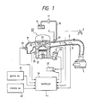
- Fig. 1 there is schematically shown an overall construction of an internal combustion engine, to which a fuel injection control apparatus according to an embodiment of the present invention is applied.
- air is introduced through air cleaner 1 to suction pipe 3.
- throttle valve 5 which is manipulated by a driver through accelerator pedal 7.
- an opening sensor is equipped to the throttle valve 5, which produces a valve opening signal.
- airflow sensor 9 in the suction pipe 3, which detects the quantity Q a of air sucked into the engine to produce an airflow signal.
- Injector 13 is installed in the suction pipe 3 near inlet valve 11.
- the injector 13 is coupled to fuel tank 15 through fuel pump 17 and fuel pipe 19 and supplied with pressure-regulated fuel.
- An injection pulse signal which will be described in detail later, is applied to the injector 13.
- the injector 13 opens its valve for time of a pulse width of the injection pulse signal applied and injects an amount of fuel in response thereto, whereby fuel mixture of a predetermined air/fuel (A/F) ratio is formed.
- the inlet valve 11 When the inlet valve 11 is opened, the mixture is sucked into combustion chamber 21 of the engine 23. The mixture is compressed and ignited to be burnt. The ignition is performed by an ignition spark plug (not shown), to which a high voltage is applied by ignition unit 27 through distributor 25, a shaft of which rotates associated with the rotation of a crank shaft (not shown) of the engine 23.
- a rotation sensor detects a rotational angle of the crank shaft of the engine 23 to produce a rotation signal for every predetermined rotational angle thereof and the other sensor, called a position sensor, detects a predetermined position of the crank shaft to produce a position signal.
- exhaust gas is discharged to exhaust pipe 31, when outlet valve 29 is opened.
- the exhaust pipe 31 is equipped with oxygen sensor 33, which detects an air/fuel ratio of the supplied mixture from the concentration of residual oxygen remaining in the exhaust gas and produces an A/F ratio signal. Accordingly, the sensor 33 functions as an A/F ratio sensor and will be so called in the following description.
- water temperature sensor 35 To a side wall of a cylinder block of the engine 23 there is equipped water temperature sensor 35, which detects a temperature of cooling water within water jacket 37 to produce a water temperature signal as a signal indicative of an operating temperature of the engine 23.
- the control apparatus of the embodiment has controller 39 including a microprocessor, to which signals produced by the various sensors as mentioned above are applied. Signals from ignition switch 41 and starter switch 43 are also given to the controller 39.
- the controller 39 executes a predetermined processing in accordance with various programs stored therein on the basis of the signals applied, whereby the injection pulse signal and the ignition timing signal are produced to the injector 13 and the ignition unit 27, respectively.
- valve opening sensor 45 is equipped to the throttle valve 5, and rotation sensor 47 and position sensor 49 are provided in the distributor 25.
- the controller 39 is composed of a microprocessor and appropriate peripheral equipment.
- the microprocessor as usual, comprises central processing unit (CPU) 51 for executing various predetermined processing, read-only memory (ROM) 53 for storing programs for the predetermined processing and various variables necessary for executing the programs and random access memory (RAM) 55 for temporarily storing various data.
- the microprocessor has another random access memory 57 called a backup RAM, which is backed up by battery 59 and stores data which is to be maintained even after the stop of operation of the engine 23.
- These components of the microprocessor are coupled with each other through bus line 61.
- the microprocessor As the peripheral equipment, the microprocessor as mentioned above is provided with the following input/output equipment. First of all, there is coupled analog to digital converter (A/D) 63 to the bus line 61, which receives analog signals from the A/F ratio sensor 33, the valve opening sensor 45, the water temperature sensor 35 and the airflow sensor 9 and converts them into digital signals. The respective signals converted in the digital form are taken into necessary components of the microprocessor through the bus line 61.
- A/D analog to digital converter
- counter 65 which counts pulses supplied by the rotation sensor 47 for every predetermined period to produce a rotation signal proportional to the rotational speed of the engine 23. Also the rotation signal is taken into necessary components of the microprocessor through the bus line 61. Furthermore, there is coupled latch 67 to the bus line 61, in which signals from the position sensor 49, the ignition switch 41 and the starter switch 43 are temporarily kept, until they are taken into the microprocessor.
- output buffer register 69 In addition to the input peripheral equipment as mentioned above, there is further coupled output buffer register 69 to the bus line 61.
- the buffer 69 temporarily stores the result of the processing in the microprocessor and outputs it to actuator 71 at appropriate timing.
- the output signal from the buffer 69 is converted in the analog form to be supplied to the actuator 71, whereby the injector 13 is driven in response to the processing result of the microprocessor.
- control signals which are generated by the CPU 51 executing the predetermined processing and given to the respective equipment through control lines.
- control lines are omitted, too.
- the amount of fuel to be injected by the injector 13 will be indicated in terms of time (fuel injection time) of a pulse width of an injection pulse signal applied to the injector 13.
- a basic fuel injection time T i ′ is determined in proportion to the ratio Qa/N of the suction air quantity Qa to the rotational speed N.
- the constant k1 is a proportional constant therefor.
- the thus obtained basic fuel injection time T i ′ is corrected in response to an A/F ratio detected, for example.
- the formula (1) above does not include a factor for such correction in order to simplify the description, it will be easily understood that such factor can be incorporated in the formula (1).
- the basic fuel injection time T i ′ as mentioned above can be determined by using other fundamental parameters indicative of the operational condition of the engine 23, such as the opening of the throttle valve 5, the negative pressure within the suction pipe 3 etc. as well as the rotational speed N of the engine 23. It is to be noted that the present invention is not subject to any limitation by the way of determining the basic fuel injection time T i ′.
- the constant k2 is a coefficient, which is provided in accordance with the present invention, for the purpose of correcting the basic fuel injection time T i ′ as obtained above.
- the correction coefficient k2 is zero during the normal operating condition and assumes appropriate values determined by the present invention when the acceleration or deceleration of the engine 23 is required.
- the engine 23 is supplied with the amount of fuel determined according to the formula (1) twice for every one rotation thereof at predetermined timing. If, however, especially rapid acceleration is required, the engine 23 can be supplied with extra fuel by the interruption injection which is not synchronized with the predetermined timing, similarly to the conventional fuel injection control.
- the determination of the correction coefficient k2 is performed by using the fuzzy reasoning. To this end, the following linguistic control rules are provided;
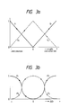
- Indexes including the fuzziness are defined by membership functions in the fuzzy technique.
- Figs. 3a and 3b show examples of such membership functions.
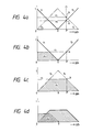
- an abscissa indicates the degree of acceleration or deceleration required in terms ⁇ t , which is the changing rate per unit time of the opening degree ⁇ t of the throttle valve 5.
- An ordinate in the figures is a non-dimensional axis.
- Figs. 3a and 3b there are provided four membership functions f1, f2, f3, f4 and f1′, f2′, f3′, f4′, respectively.
- every membership function changes between 0 and 1 with respect to ⁇ t .
- the membership functions f1, f2, f3, f4 of Fig. 3a are all linear and therefore suited for universal use.
- the membership functions f1′, f2′, f3′, f4′ of Fig. 3b are composed of two continuing arcs of a quarter of a circle, respectively.
- a first figure as indicated by a hatched portion in Fig. 4b is formed by the membership function f1 and the line r2, and then an area A1 thereof is obtained by the calculation.
- a second figure as indicated by a hatched portion in Fig. 4c is formed by the membership functions f3 and f4 and the line r3, and an area A2 thereof is calculated.
- a third figure as surrounded by a thick line and the coordinate axes in Fig. 4d can be formed. Further, if the areas A1 and A2 are added to each other and an area A3 of an overlapped portion in the third figure is subtracted from the summation A1 + A2, an area A of the third figure can be obtained.
- the correction coefficient k2 is determined on the basis of the thus obtained third figure. Referring to Figs. 5a and 5b, the way of determining it will be explained below. It is to be noted that the abscissa in Fig. 5a is represented as the correction coefficient k2, which is converted from the changing rate ⁇ t of the opening of the throttle valve 5 simply in the proportional relationship.
- centroid M of the third figure is obtained as shown in Fig. 5. If coordinates of the obtained centroid M is expressed by (x m , y m ), x m on the abscissa affords the correction coefficient k2. In the case as shown in Fig. 5a, a negative value is obtained as the correction coefficient k2. If this value is applied to the formula (1), the basic fuel injection time T i ′ is corrected so as to increase accordingly.
- the aforesaid x m of the centroid M is obtained as follows.
- the base (abscissa) of the third figure is divided into plural segments at equal intervals.
- Values y1, y2, y3, y4, etc, y i of the ordinate for every segment are added one after another from the right end of the figure. If the intervals of the segments are selected to sufficiently small, the summation of this addition becomes substantially equal to an area S Ri of a portion of the figure, which is on the right-hand side with respect to y i .
- the foregoing has been concerned the case where it was detected that the acceleration is required.
- the correction coefficient k2 when it is detected that the deceleration is required can be determined in the analogous manner. This will be explained briefly, referring to Figs. 6a to 6d.
- a third figure as surrounded by a thick line and the coordinate axes in the figure is formed.
- the centroid M of the thus obtained third figure is obtained and the correction coefficient k2 can be determined on the basis of a value of the abscissa of the centroid M.
- this processing operation is executed for every 2 to 10 msec. Thereafter, at first, the suction air quantity Q a , the rotational speed N, the valve opening ⁇ t and the water temperature T W are taken into the microprocessor from the respective sensors at step 701, and they are temporarily stored in appropriate areas of the RAM 55.
- the basic fuel injection time T i ′ is calculated on the basis of the suction air quantity Q a and the rotational speed N. As already described, the consideration of the correction based on the A/F ratio is omitted here. Then, at step 703, the changing rate ⁇ t of the valve opening ⁇ t is calculated. This is obtained on the basis of the difference between the value of ⁇ t stored in the execution cycle of last time and that read this time.
- step 704 it is judged at step 704 whether or not ⁇ t is positive. If ⁇ t is discriminated to be positive, this means that the acceleration is required. This is the case that has been explained with reference to Figs. 4a to 4d. In this case, the processing operation goes to step 705. When ⁇ t is discriminated to be not positive, the processing operation goes to step 721 of Fig. 7b, since the deceleration is required. The processing operation of step 721 and the following will be described later.
- a set of membership functions is selected in accordance with the water temperature T W from among various membership functions prepared in advance.
- the membership functions f1 to f4 as shown in Fig. 3a are selected.
- a value of the function f2 in response to ⁇ t obtained at step 703 is calculated. This value corresponds to a value of the ordinate of the cross point a as shown in Fig. 4a.
- the area A1 of the first figure as shown in Fig. 4b is calculated at step 708.
- a value of the function f4 in response to ⁇ t obtained at step 703 is calculated. This value corresponds to a value of the cross point b as shown in Fig. 4a.
- the area A2 of the second figure as shown in Fig. 4c is calculated at step 710.
- the area A1 is added to the area A2 to obtain the summation A0 at step 711.
- the area A3 of the overlapped portion of the third figure as shown in Fig. 4d is calculated.
- the area A3 of the overlapped portion is subtracted from the summation A0 to thereby obtain the area A of the third figure.
- the centroid of the third figure is obtained, and the correction coefficient k2 is determined on the basis of the centroid obtained.
- the basic fuel injection time T i ′ obtained at step 702 is corrected by using the correction coefficient k2 as determined above, and the processing operation ends.
- a set of membership functions is selected in accordance with the water temperature T W .
- a value of the function f1 in response to ⁇ t obtained at step 703 is calculated. This value corresponds to a value of the ordinate of the cross point a′ as shown in Fig. 6a.
- the area A1′ of the first figure as shown in Fig. 6b is calculated at step 723.
- a value of the function f3 in response to ⁇ t obtained at step 703 is calculated. This value corresponds to a value of the ordinate of the cross point b′ as shown in Fig. 6a. Then, the area A2′ of the second figure as shown in Fig. 6c is calculated at step 725.
- the area A1′ is added to the area A2′ to obtain the summation A0′ at step 726.
- the area A3′ of the overlapped portion of the third figure is calculated.
- the area A3′ of the overlapped portion is subtracted from the summation A0′ to thereby obtain the area A′ of the third figure.
- step 729 the centroid of the third figure is obtained, and the correction coefficient k2 is determined on the basis of the centroid obtained. Thereafter, the processing operation goes to step 715 of Fig. 7a, at which the basic fuel injection time T i ′ obtained at step 702 is corrected by using the correction coefficient k2 as determined above, and the processing operation ends.
- a suction air temperature, an atmospheric pressure, etc. may be used as further criteria for selecting a specific set from the stored membership functions.
- every factor which gives an influence on determination of the amount of fuel to be injected can be used as the criterium for selecting the respective set of membership functions.
Applications Claiming Priority (2)
| Application Number | Priority Date | Filing Date | Title |
|---|---|---|---|
| JP63257157A JPH02104929A (ja) | 1988-10-14 | 1988-10-14 | 電子制御燃料噴射装置 |
| JP257157/88 | 1988-10-14 |
Publications (3)
| Publication Number | Publication Date |
|---|---|
| EP0363958A2 true EP0363958A2 (de) | 1990-04-18 |
| EP0363958A3 EP0363958A3 (de) | 1991-09-11 |
| EP0363958B1 EP0363958B1 (de) | 1994-01-19 |
Family
ID=17302497
Family Applications (1)
| Application Number | Title | Priority Date | Filing Date |
|---|---|---|---|
| EP89118982A Expired - Lifetime EP0363958B1 (de) | 1988-10-14 | 1989-10-12 | Methode und Vorrichtung zum Steuern der Kraftstoffeinspritzung für Brennkraftmaschinen |
Country Status (5)
| Country | Link |
|---|---|
| US (2) | US4966118A (de) |
| EP (1) | EP0363958B1 (de) |
| JP (1) | JPH02104929A (de) |
| KR (1) | KR900006655A (de) |
| DE (1) | DE68912499T2 (de) |
Cited By (4)
| Publication number | Priority date | Publication date | Assignee | Title |
|---|---|---|---|---|
| WO1995020141A1 (en) * | 1994-01-25 | 1995-07-27 | Rosemount Inc. | Transmitter with improved compensation |
| DE19604469A1 (de) * | 1996-02-09 | 1997-08-14 | Iav Gmbh | Einrichtung zur Regelung der Kraftstoffmenge für Verbrennungsmotoren von Fahrzeugen mit einem einstellbaren Geschwindigkeitsregler |
| EP0831225A2 (de) * | 1996-09-18 | 1998-03-25 | Toyota Jidosha Kabushiki Kaisha | Brennstoff-Einspritzvorrichtung |
| US6047244A (en) * | 1997-12-05 | 2000-04-04 | Rosemount Inc. | Multiple range transition method and apparatus for process control sensors |
Families Citing this family (15)
| Publication number | Priority date | Publication date | Assignee | Title |
|---|---|---|---|---|
| JPH02104929A (ja) * | 1988-10-14 | 1990-04-17 | Hitachi Ltd | 電子制御燃料噴射装置 |
| WO1990006428A1 (en) * | 1988-12-10 | 1990-06-14 | Robert Bosch Gmbh | Adaptive acceleration enrichment for petrol injection systems |
| JPH02188644A (ja) * | 1989-01-14 | 1990-07-24 | Nok Corp | 燃料噴射制御装置 |
| US5239616A (en) * | 1989-04-14 | 1993-08-24 | Omron Corporation | Portable fuzzy reasoning device |
| US5069187A (en) * | 1989-09-05 | 1991-12-03 | Honda Giken Kogyo K.K. | Fuel supply control system for internal combustion engines |
| US5233682A (en) * | 1990-04-10 | 1993-08-03 | Matsushita Electric Industrial Co., Ltd. | Vacuum cleaner with fuzzy control |
| JPH0488558A (ja) * | 1990-08-01 | 1992-03-23 | Nissan Motor Co Ltd | デザイン装置 |
| JPH04195338A (ja) * | 1990-11-28 | 1992-07-15 | Hitachi Ltd | ファジィ推論方式 |
| JPH04335432A (ja) * | 1991-05-10 | 1992-11-24 | Omron Corp | メンバーシップ関数データ作成方法および装置ならびに適合度演算方法および装置 |
| US5227678A (en) * | 1991-05-22 | 1993-07-13 | Illinois Institute Of Technology | Fast digital comparison circuit for fuzzy logic operations |
| US5993194A (en) * | 1996-06-21 | 1999-11-30 | Lemelson; Jerome H. | Automatically optimized combustion control |
| US6227842B1 (en) | 1998-12-30 | 2001-05-08 | Jerome H. Lemelson | Automatically optimized combustion control |
| US6468069B2 (en) | 1999-10-25 | 2002-10-22 | Jerome H. Lemelson | Automatically optimized combustion control |
| US9427837B2 (en) | 2011-07-12 | 2016-08-30 | Ntn Corporation | Clamping method for clamping a boot band |
| TWI593875B (zh) * | 2016-01-21 | 2017-08-01 | Rong-Bin Liao | Engine control |
Citations (5)
| Publication number | Priority date | Publication date | Assignee | Title |
|---|---|---|---|---|
| US4469073A (en) * | 1982-02-23 | 1984-09-04 | Toyota Jidosha Kogyo Kabushiki Kaisha | Electronic fuel injecting method and device for internal combustion engine |
| US4520783A (en) * | 1983-08-01 | 1985-06-04 | Toyota Jidosha Kabushiki Kaisha | Method of controlling fuel injection and apparatus therefor |
| US4589389A (en) * | 1984-06-15 | 1986-05-20 | Hitachi, Ltd. | Fuel injection control apparatus for internal combustion engines |
| EP0256786A2 (de) * | 1986-08-06 | 1988-02-24 | Honda Giken Kogyo Kabushiki Kaisha | Fahrzeug-Regelsystem und Methode dafür |
| JPS63227958A (ja) * | 1987-03-17 | 1988-09-22 | Japan Electronic Control Syst Co Ltd | 内燃機関の点火時期制御装置 |
Family Cites Families (18)
| Publication number | Priority date | Publication date | Assignee | Title |
|---|---|---|---|---|
| JPS6047460B2 (ja) * | 1977-10-19 | 1985-10-22 | トヨタ自動車株式会社 | 燃料噴射制御装置 |
| JPS5815725A (ja) * | 1981-07-21 | 1983-01-29 | Japan Electronic Control Syst Co Ltd | 内燃機関の電子制御燃料噴射装置 |
| JPS58148238A (ja) * | 1982-02-25 | 1983-09-03 | Toyota Motor Corp | 内燃機関の電子制御燃料噴射方法 |
| KR910008882B1 (ko) * | 1982-04-27 | 1991-10-24 | 가부시기가이샤 히다찌세이사꾸쇼 | 정위치 정차방법 및 장치 |
| US4616619A (en) * | 1983-07-18 | 1986-10-14 | Nippon Soken, Inc. | Method for controlling air-fuel ratio in internal combustion engine |
| US4723524A (en) * | 1985-06-05 | 1988-02-09 | Hitachi, Ltd. | Fuel injection controlling method for an internal combustion engine |
| JPS6332137A (ja) * | 1986-07-28 | 1988-02-10 | Japan Electronic Control Syst Co Ltd | 内燃機関の電子制御燃料噴射装置 |
| JPH0714707B2 (ja) * | 1986-12-10 | 1995-02-22 | 日産自動車株式会社 | 自動車用定速走行装置 |
| JPH0733805B2 (ja) * | 1987-01-07 | 1995-04-12 | 株式会社ユニシアジェックス | 内燃機関の加・減速判定装置 |
| JP2582562B2 (ja) * | 1987-02-21 | 1997-02-19 | 株式会社ユニシアジェックス | 内燃機関の空燃比制御装置 |
| US4862854A (en) * | 1987-04-06 | 1989-09-05 | Mazda Motor Corporation | Control systems for vehicle engines |
| EP0292286B1 (de) * | 1987-05-19 | 1993-02-03 | Honda Giken Kogyo Kabushiki Kaisha | Fahrzeug-Regelsystem |
| JP2681930B2 (ja) * | 1987-06-27 | 1997-11-26 | 株式会社デンソー | サーボ制御装置 |
| JPS649036A (en) * | 1987-07-01 | 1989-01-12 | Nissan Motor | Constant speed running device for automobile |
| US4926826A (en) * | 1987-08-31 | 1990-05-22 | Japan Electronic Control Systems Co., Ltd. | Electric air-fuel ratio control apparatus for use in internal combustion engine |
| JPH01132450A (ja) * | 1987-11-17 | 1989-05-24 | Nissan Motor Co Ltd | アンチスキッドブレーキシステム |
| JPH02104929A (ja) * | 1988-10-14 | 1990-04-17 | Hitachi Ltd | 電子制御燃料噴射装置 |
| JP2757193B2 (ja) * | 1988-11-18 | 1998-05-25 | トヨタ自動車株式会社 | 車両の走行目標値の設定装置 |
-
1988
- 1988-10-14 JP JP63257157A patent/JPH02104929A/ja active Pending
-
1989
- 1989-10-03 US US07/416,408 patent/US4966118A/en not_active Expired - Fee Related
- 1989-10-10 KR KR1019890014532A patent/KR900006655A/ko not_active IP Right Cessation
- 1989-10-12 DE DE68912499T patent/DE68912499T2/de not_active Expired - Fee Related
- 1989-10-12 EP EP89118982A patent/EP0363958B1/de not_active Expired - Lifetime
-
1990
- 1990-10-23 US US07/601,433 patent/US5146898A/en not_active Expired - Fee Related
Patent Citations (5)
| Publication number | Priority date | Publication date | Assignee | Title |
|---|---|---|---|---|
| US4469073A (en) * | 1982-02-23 | 1984-09-04 | Toyota Jidosha Kogyo Kabushiki Kaisha | Electronic fuel injecting method and device for internal combustion engine |
| US4520783A (en) * | 1983-08-01 | 1985-06-04 | Toyota Jidosha Kabushiki Kaisha | Method of controlling fuel injection and apparatus therefor |
| US4589389A (en) * | 1984-06-15 | 1986-05-20 | Hitachi, Ltd. | Fuel injection control apparatus for internal combustion engines |
| EP0256786A2 (de) * | 1986-08-06 | 1988-02-24 | Honda Giken Kogyo Kabushiki Kaisha | Fahrzeug-Regelsystem und Methode dafür |
| JPS63227958A (ja) * | 1987-03-17 | 1988-09-22 | Japan Electronic Control Syst Co Ltd | 内燃機関の点火時期制御装置 |
Non-Patent Citations (2)
| Title |
|---|
| PROC. OF THE 26TH S.I.C.E. ANNUAL CONFERENCE II 15 July 1987, Hiroshima JP. & AL.: "APPLICATION OF A SELF-TUNING FUZZY LOGIC SYSTEM TO AUTOMATIC SPEED CONTROL DEVICES" * |
| PROC. OF THE 26TH S.I.C.E. ANNUAL CONFERENCE II, 15 July 1987, Hiroshima JP. pages 1241 - 1244; TAKASHI & AL.: "APPLICATION OF A SELF-TUNING FUZZY LOGIC SYSTEM TO AUTOMATIC SPEED CONTROL DEVICES" * |
Cited By (7)
| Publication number | Priority date | Publication date | Assignee | Title |
|---|---|---|---|---|
| WO1995020141A1 (en) * | 1994-01-25 | 1995-07-27 | Rosemount Inc. | Transmitter with improved compensation |
| US5642301A (en) * | 1994-01-25 | 1997-06-24 | Rosemount Inc. | Transmitter with improved compensation |
| US5960375A (en) * | 1994-01-25 | 1999-09-28 | Rosemount Inc. | Transmitter with improved compensation |
| DE19604469A1 (de) * | 1996-02-09 | 1997-08-14 | Iav Gmbh | Einrichtung zur Regelung der Kraftstoffmenge für Verbrennungsmotoren von Fahrzeugen mit einem einstellbaren Geschwindigkeitsregler |
| EP0831225A2 (de) * | 1996-09-18 | 1998-03-25 | Toyota Jidosha Kabushiki Kaisha | Brennstoff-Einspritzvorrichtung |
| EP0831225A3 (de) * | 1996-09-18 | 2000-01-05 | Toyota Jidosha Kabushiki Kaisha | Brennstoff-Einspritzvorrichtung |
| US6047244A (en) * | 1997-12-05 | 2000-04-04 | Rosemount Inc. | Multiple range transition method and apparatus for process control sensors |
Also Published As
| Publication number | Publication date |
|---|---|
| JPH02104929A (ja) | 1990-04-17 |
| KR900006655A (ko) | 1990-05-08 |
| DE68912499D1 (de) | 1994-03-03 |
| EP0363958A3 (de) | 1991-09-11 |
| US5146898A (en) | 1992-09-15 |
| EP0363958B1 (de) | 1994-01-19 |
| DE68912499T2 (de) | 1994-07-21 |
| US4966118A (en) | 1990-10-30 |
Similar Documents
| Publication | Publication Date | Title |
|---|---|---|
| EP0363958A2 (de) | Methode und Vorrichtung zum Steuern der Kraftstoffeinspritzung für Brennkraftmaschinen | |
| JP2638793B2 (ja) | 空燃比制御装置 | |
| US4598684A (en) | Apparatus for controlling air/fuel ratio for internal combustion engine | |
| JPH01177431A (ja) | 内燃機関の電子スロツトル制御装置 | |
| EP0130382A1 (de) | Kraftstoff-Einspritzverfahren für einen Motor | |
| US4800857A (en) | Apparatus for learn-controlling air-fuel ratio for internal combustion engine | |
| US5220828A (en) | Throttle valve position detecting apparatus | |
| US6725149B2 (en) | Electronic control device for internal combustion engine | |
| US5522366A (en) | Fuel injection control apparatus for internal combustion engine | |
| US4685436A (en) | Fuel injection control device for internal combustion engine | |
| US4982714A (en) | Air-fuel control apparatus for an internal combustion engine | |
| US4520784A (en) | Method of and apparatus for controlling fuel injection | |
| US4715350A (en) | Air intake side secondary air supply system for an internal combustion engine with a duty ratio control operation | |
| JP2650034B2 (ja) | 内燃機関の減速制御装置 | |
| JPH0689682B2 (ja) | 空燃比制御装置 | |
| US4962663A (en) | Method of measuring atmospheric pressure for an internal combustion engine | |
| JP2502500B2 (ja) | エンジンの制御装置 | |
| JP2870201B2 (ja) | Egr装置 | |
| JPH04342857A (ja) | 内燃機関の電子制御装置 | |
| JPH0429855B2 (de) | ||
| JPH01294933A (ja) | 内燃機関の補助空気制御装置 | |
| JP2940916B2 (ja) | 内燃機関の空燃比制御装置 | |
| JP3054979B2 (ja) | 内燃機関の壁流補正制御装置 | |
| JPH0742916B2 (ja) | エンジンの点火時期制御装置 | |
| JPS62225739A (ja) | 内燃機関のアイドル回転数制御装置 |
Legal Events
| Date | Code | Title | Description |
|---|---|---|---|
| PUAI | Public reference made under article 153(3) epc to a published international application that has entered the european phase |
Free format text: ORIGINAL CODE: 0009012 |
|
| AK | Designated contracting states |
Kind code of ref document: A2 Designated state(s): DE FR GB |
|
| 17P | Request for examination filed |
Effective date: 19901122 |
|
| PUAL | Search report despatched |
Free format text: ORIGINAL CODE: 0009013 |
|
| AK | Designated contracting states |
Kind code of ref document: A3 Designated state(s): DE FR GB |
|
| 17Q | First examination report despatched |
Effective date: 19920117 |
|
| GRAA | (expected) grant |
Free format text: ORIGINAL CODE: 0009210 |
|
| AK | Designated contracting states |
Kind code of ref document: B1 Designated state(s): DE FR GB |
|
| RBV | Designated contracting states (corrected) |
Designated state(s): DE |
|
| REF | Corresponds to: |
Ref document number: 68912499 Country of ref document: DE Date of ref document: 19940303 |
|
| PLBE | No opposition filed within time limit |
Free format text: ORIGINAL CODE: 0009261 |
|
| STAA | Information on the status of an ep patent application or granted ep patent |
Free format text: STATUS: NO OPPOSITION FILED WITHIN TIME LIMIT |
|
| 26N | No opposition filed | ||
| PG25 | Lapsed in a contracting state [announced via postgrant information from national office to epo] |
Ref country code: DE Effective date: 19950701 |