EP0363307B1 - Récipient de distribution pour produits pâteux - Google Patents
Récipient de distribution pour produits pâteux Download PDFInfo
- Publication number
- EP0363307B1 EP0363307B1 EP89810070A EP89810070A EP0363307B1 EP 0363307 B1 EP0363307 B1 EP 0363307B1 EP 89810070 A EP89810070 A EP 89810070A EP 89810070 A EP89810070 A EP 89810070A EP 0363307 B1 EP0363307 B1 EP 0363307B1
- Authority
- EP
- European Patent Office
- Prior art keywords
- container
- intermediate store
- opening
- diaphragm
- pin
- Prior art date
- Legal status (The legal status is an assumption and is not a legal conclusion. Google has not performed a legal analysis and makes no representation as to the accuracy of the status listed.)
- Expired - Lifetime
Links
Images


Classifications
-
- B—PERFORMING OPERATIONS; TRANSPORTING
- B65—CONVEYING; PACKING; STORING; HANDLING THIN OR FILAMENTARY MATERIAL
- B65D—CONTAINERS FOR STORAGE OR TRANSPORT OF ARTICLES OR MATERIALS, e.g. BAGS, BARRELS, BOTTLES, BOXES, CANS, CARTONS, CRATES, DRUMS, JARS, TANKS, HOPPERS, FORWARDING CONTAINERS; ACCESSORIES, CLOSURES, OR FITTINGS THEREFOR; PACKAGING ELEMENTS; PACKAGES
- B65D83/00—Containers or packages with special means for dispensing contents
- B65D83/0005—Containers or packages provided with a piston or with a movable bottom or partition having approximately the same section as the container
- B65D83/0033—Containers or packages provided with a piston or with a movable bottom or partition having approximately the same section as the container the piston being a follower-piston and the dispensing means comprising a hand-operated pressure-device at the opposite part of the container
-
- B—PERFORMING OPERATIONS; TRANSPORTING
- B05—SPRAYING OR ATOMISING IN GENERAL; APPLYING FLUENT MATERIALS TO SURFACES, IN GENERAL
- B05B—SPRAYING APPARATUS; ATOMISING APPARATUS; NOZZLES
- B05B11/00—Single-unit hand-held apparatus in which flow of contents is produced by the muscular force of the operator at the moment of use
- B05B11/0005—Components or details
- B05B11/0037—Containers
- B05B11/0039—Containers associated with means for compensating the pressure difference between the ambient pressure and the pressure inside the container, e.g. pressure relief means
- B05B11/0044—Containers associated with means for compensating the pressure difference between the ambient pressure and the pressure inside the container, e.g. pressure relief means compensating underpressure by ingress of atmospheric air into the container, i.e. with venting means
- B05B11/00446—Containers associated with means for compensating the pressure difference between the ambient pressure and the pressure inside the container, e.g. pressure relief means compensating underpressure by ingress of atmospheric air into the container, i.e. with venting means the means being located at the bottom of the container or of an enclosure surrounding the container
-
- B—PERFORMING OPERATIONS; TRANSPORTING
- B05—SPRAYING OR ATOMISING IN GENERAL; APPLYING FLUENT MATERIALS TO SURFACES, IN GENERAL
- B05B—SPRAYING APPARATUS; ATOMISING APPARATUS; NOZZLES
- B05B11/00—Single-unit hand-held apparatus in which flow of contents is produced by the muscular force of the operator at the moment of use
- B05B11/01—Single-unit hand-held apparatus in which flow of contents is produced by the muscular force of the operator at the moment of use characterised by the means producing the flow
- B05B11/02—Membranes or pistons acting on the contents inside the container, e.g. follower pistons
- B05B11/028—Pistons separating the content remaining in the container from the atmospheric air to compensate underpressure inside the container
-
- B—PERFORMING OPERATIONS; TRANSPORTING
- B05—SPRAYING OR ATOMISING IN GENERAL; APPLYING FLUENT MATERIALS TO SURFACES, IN GENERAL
- B05B—SPRAYING APPARATUS; ATOMISING APPARATUS; NOZZLES
- B05B11/00—Single-unit hand-held apparatus in which flow of contents is produced by the muscular force of the operator at the moment of use
- B05B11/01—Single-unit hand-held apparatus in which flow of contents is produced by the muscular force of the operator at the moment of use characterised by the means producing the flow
- B05B11/10—Pump arrangements for transferring the contents from the container to a pump chamber by a sucking effect and forcing the contents out through the dispensing nozzle
- B05B11/1001—Piston pumps
- B05B11/1016—Piston pumps the outlet valve having a valve seat located downstream a movable valve element controlled by a pressure actuated controlling element
- B05B11/1018—Piston pumps the outlet valve having a valve seat located downstream a movable valve element controlled by a pressure actuated controlling element and the controlling element cooperating with means for opening or closing the inlet valve
-
- B—PERFORMING OPERATIONS; TRANSPORTING
- B05—SPRAYING OR ATOMISING IN GENERAL; APPLYING FLUENT MATERIALS TO SURFACES, IN GENERAL
- B05B—SPRAYING APPARATUS; ATOMISING APPARATUS; NOZZLES
- B05B11/00—Single-unit hand-held apparatus in which flow of contents is produced by the muscular force of the operator at the moment of use
- B05B11/01—Single-unit hand-held apparatus in which flow of contents is produced by the muscular force of the operator at the moment of use characterised by the means producing the flow
- B05B11/10—Pump arrangements for transferring the contents from the container to a pump chamber by a sucking effect and forcing the contents out through the dispensing nozzle
- B05B11/1028—Pumps having a pumping chamber with a deformable wall
- B05B11/1036—Pumps having a pumping chamber with a deformable wall the outlet valve being opened in the direction opposite to the fluid flow downstream the outlet valve by the pressure acting on a valve controlling element
Definitions
- the present invention relates to a can designed as a dispenser for pasty products.
- a dispenser for a pasty mass with an air inlet opening in the can bottom, an axially displaceable piston arranged behind it, which separates the pasty product from the can bottom, and a can end arranged opposite the can bottom, which contains an intermediate store an inlet valve that releases the inlet of the pasty product from the inside of the can and an outlet valve that enables the pasty product to emerge from the can, and an elastic part that serves to reversibly reduce the size of the intermediate store, the outlet valve being followed by a flat, intermediate store is formed on the outside, with a hole serving as an outlet opening, and a pin arranged in the intermediate store, on which the outlet opening of the closing member rests with its edge.
- this known construction has obvious disadvantages: on the one hand, for trouble-free operation of the dispenser, that is, in order to protect the pasty product from constant air contact, the volume of the intermediate store should be reduced to zero after each use, which will hardly occur, and on the other hand it is Slidable pistons are secured by a clamping module against sliding towards the bottom of the can, but this has the consequence that sliding in the other direction is impeded accordingly, so that it is unlikely that the spring force of the bellows-shaped pump wall can be sufficient. Furthermore, this dispenser has a button on the side that must be actuated in order to cause the product to be dispensed through the outlet opening made in the top cover of the housing.
- a container which can obviously be used for toothpaste is known, which is also provided with an air inlet opening in the container base, an axially displaceable piston arranged behind it, which separates the pasty product from the base, and a container closure arranged opposite the container base,
- the container closure contains an intermediate store with an inlet valve that releases the inlet of the pasty product from the inside of the container and an outlet valve that allows the pasty product to exit from the intermediate store to the outside, as well as an elastic section that serves to reversibly reduce the size of the intermediate store.
- This design may be very useful for toothpaste, since it has a dispensing channel that can be closed by a cap, as the user is used to from the toothpaste tube.
- a body care cream such as. B. a hand or face cream
- the user of such personal care products is used to remove such agents with a finger from a flat can, which he usually closes after use with a large lid, and on the other hand, because there is always a risk that the part of the fine hand or face cream in the delivery channel becomes hard as a result of drying out, can therefore no longer be used well and the outlet opening becomes blocked.
- the intermediate store has a volume that cannot be reduced to zero and that the valves are non-return valves which can be actuated by the product in the intermediate store, either the closing element as an elastic membrane of the part designed to reduce the size of the buffer or the pin is mounted elastically.
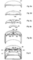
- the can according to the invention essentially consists of the can base 1, which has an air inlet opening 1 a, the can wall 2, the can end designated as a whole as 3, and the piston 4 which is axially displaceable within the can.
- the can end 3 contains an intermediate store, the space of which is designated 5. It is bounded at the bottom, that is to say against the interior of the container 7, by the rigid end plate 6 and at the top, that is to say towards the outside, by the elastic membrane 8. Both the end plate 6 of the intermediate store and the membrane 8 are in some way not shown in the drawing and firmly connected to the wall 2.
- the end plate 6 is provided with an inlet opening 6a which, together with the flap 10, forms an inlet valve.
- This flap can be made of soft or stiff material.
- both the container interior 7 and the space 5 of the buffer store are filled with the pasty product.
- the cream dispenser is used, so that the volume of the intermediate store 5 is reduced by pressure on the membrane 8, so that the pasty content bulges the membrane outwards, so that it is raised where it rests on the pin 9. This allows some of the contents to escape through the opening 8a onto the top of the membrane, from where it can be wiped away and used with the finger.
- the space 5 returns to its original volume. This pasty mass is sucked from room 7 into room 5.
- the displaceable piston 4 is correspondingly pulled upwards until the space 7 is completely empty and the piston 4 abuts the end plate 6.
- FIG. 2 A first exemplary embodiment is shown in FIG. 2.
- the can wall 12 and the end bottom 16 of the can end consist of a single workpiece.
- a pin 19 is formed in the middle of the end plate 16, on which the membrane 18 rests, which is provided with an opening 18a in the middle and is firmly connected at its circular edge to the edge 16b of the end plate 16.
- the membrane 18 and the end plate 16 delimit a buffer store 15, which is connected via an opening 16a to the space 17, that is to say the interior of the can, a flap 20 articulated on the membrane 18 being designed such that the contents escape from the space 17 into the intermediate storage 15, but nothing can return from the intermediate storage 15 into the space 17.
- the shape of the edge 18b of the membrane 18 ensures that the membrane can be elastically deformed against the end base 16 by an external pressure and that it resumes the original shape when such an external load ceases, with a pumping action occurring in each case.
- the membrane 18 is first firmly connected to the end plate 16 of the intermediate store 15. Then the space 17 is filled with the paste in such a way that the paste also enters the intermediate storage 15 and fills it completely. Then the piston 14 is inserted, the insertion of this piston can also be used to convey paste from the space 17 into the intermediate storage 15.
- the can base 11 provided with an air inlet opening 11a is placed on the wall 12, to which it is held, for example by means of a snap connection. However, depending on the choice of material, it can also be permanently connected to the can wall 12 by welding or gluing. Finally, the cover 13 serving to protect the membrane 18 is put on.
- the membrane 18 is pressed at a point not resting on the pin 19 and then released again, which has the expected pump effect:
- the paste escapes from the intermediate store 15 the opening 18a on the upper side of the membrane 18.
- the membrane returns to the original position, which increases the intermediate storage again, so that paste is drawn in from the space 17, which can be repeated until the Room 17 is empty and the piston 14 abuts the end plate 16.
- the membrane 18 can be covered again by the cover 13.
- FIG. 3 A second exemplary embodiment is shown in FIG. 3.
- the can wall 22 and the can base 21 provided with an air hole 21a consist of a single workpiece, while the end base 26 of the intermediate store 25 is inserted from above and is held on the wall 22 by a snap or adhesive connection.
- the upper end of the intermediate store 25 is also formed here by a membrane which is affixed to the upper edge of the wall 22 and has its opening 28a lying freely on the pin 29 and is designated by 28.
- the end plate 26 can, as can be seen from the drawing, form a single workpiece with the pin 29.
- This final floor is the further provided with an elastic tongue 26b which rests on the underside of the membrane 28 and whose free end is very close to the edge of the membrane 28.
- an opening 26c in this tongue 26b serves to allow the elastic holder 30a to connect the valve cover 30 to the membrane 28 elastically in order to close the inlet opening 26a.
- a lid 23 is used when not in use to protect the membrane 28 against contact.
- the piston 24, which stands on the can base with a support ring when the can is full has a relatively rigid edge 24a, which is connected to the likewise rigid central part by a roller membrane 24b, which results in a good utilization of the can volume.
- the piston 24 is first inserted into the structure consisting of the wall 22 and the can base 21.
- the paste is poured in and then the bottom plate 26 with the elastic tongue 26b is inserted, whereupon the membrane 28 is placed and fastened, which in turn is then protected by the cover, which can be easily removed for use.
- the tongue 26b can be pressed, whereby the storage space is reduced and paste is pressed out through the opening 28a. If the tongue 26b is released again, the storage space 25 increases again, with the result that paste enters through the opening 26a.
- the pin designated here 29, which together with the opening 28a forms the outlet valve can have a tapered end which projects into the opening 28a, that is to say one end that either tapered or stepped or otherwise rejuvenated. This prevents a paste residue from remaining in the opening 28a after the paste has been removed and hardening there.
- the third embodiment shown in Figure 4 has a certain correspondence with the exemplary embodiment described with reference to FIG. 2: here too, the can wall 32 and the end bottom 36 of the intermediate store 35 consist of a single workpiece, while the can bottom 31 provided with an opening 31a after the paste has been filled in and the Piston 34 is placed.
- the pin 39 and the opening 38a of the membrane 38 resting thereon are arranged outside the center of the can.
- the other difference results from the fact that the membrane 38 is partially provided with a reinforcement 38b and at the edge with a corrugation 38c, so that it can be pressed in more like a spring tongue. Since the rest of the construction and the method of operation are essentially the same, there is no need to describe them in detail, nor to describe how a filled can is manufactured.
- the can wall 42 and the closing base 46 of the buffer store provided with an opening 46a consist of a single workpiece.
- the can base 41 with the air inlet opening 41a and the displaceable piston designated by 44 and the cover 43 are similar to the corresponding parts in the embodiments already described with reference to FIGS. 2 and 4.
- the intermediate storage 45 is not only delimited here by the membrane 48 and the end plate 46, but to a not insignificant extent also by an intermediate wall, the two rectilinear sections 46b (only one of which can be seen in the drawing!) And one the pin 49 in a ring shape has surrounding section 46c and consists of a workpiece with the end plate 46.
- a cylinder 141 is arranged within the annular section 46c and is provided with a spring strip 142 and a spring arm 143 arranged between the two straight wall sections 46b, the latter of which, at its end, resiliently presses the valve cover 50 onto the opening 46a, while the spring strip 142 serves to return the membrane 48, which has been pressed in to effect the paste dispensing through the opening 48a, back to the original position.
- a cover 43 serves to protect the membrane against any pressure when not in use.
- FIGS. 6 and 6a to 6e A fifth exemplary embodiment is shown in FIGS. 6 and 6a to 6e.
- a multi-slotted disc spring 150 is inserted, which is between the pin 59 and Openings 56a rests on the end floor 56.
- the membrane 58 provided with a central opening 58a can be made of any soft material, so to speak.
- the ring 60 acting as a valve disk lies on the openings 56a.
- this exemplary embodiment can also be used in exactly the same way as the exemplary embodiments described above: pressure on the membrane 58, which can be protected by the cover 53 when not in use, counteracts the force of the Spring 150 of the intermediate store 55 is reduced in size, so that the paste present in this space presses the ring 60 on the one hand onto the openings 56a and thereby closes them, and on the other hand lifts the membrane 58 in the middle, as a result of what is formed by the pin 59 and the opening 58a Valve opens and exits there.
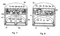
- the wall of the can, designated by 62, and the end floor, designated by 66 consist of a single workpiece, the end floor being supported by a column 66b on the can bottom 61 provided with an air inlet opening 61a, which in turn is insoluble or difficult to remove on the bottom edge the wall 62 sits.
- the piston 64 is provided with a central guide sleeve 64a so that it can gradually move from its lowest position, in which it is shown in FIG. 7, to the uppermost position without the risk of tipping.
- Two or more bores 66a in the end floor 66 connect the space 67 to the intermediate storage 65, an elastic sleeve 70 acting as a valve plate such that paste from the space 67 can get into the intermediate storage 65 through the bores 66a, but the reverse is prevented .
- the central pin 69 is connected here to the end base 66 via a membrane 69a serving as a holder, so that when the intermediate storage 65 is reduced, it is guided downward as a result of its holder 69a which moves downward, thereby opening the opening 68a in the cover 68.
- This cover is rigidly connected to the end plate 66 by individual webs.
- an annular strip 68b made of elastic material can be pressed against the end bottom 66 against the force of a spring 68c.
- the mode of operation corresponds to the mode of operation as described above with reference to the schematic diagram in FIG. 1, with the difference that in order to dispense the paste, it is not necessary to exert pressure on the elastic membrane but on the elastically mounted ring 68b.
- a cover 63 serves to protect the membrane from unintentional actuation.
- the last exemplary embodiment shown in FIG. 8 differs from the exemplary embodiment described above not so much by the fact that the elastically mounted pin, designated here by 79, does not close the cover 78 provided with an opening 78a in the middle but at another location, but much more so that the cover 78 is displaceable relative to and through it a spring 78c supported insert 78d is provided.
- the elastically mounted pin designated here by 79
- the intermediate storage space 75 delimited by the end bottom 76 and the cover 78 is reduced, so that the paste can escape from this space through the opening 78a until the overpressure generated by pressing the insert 78d has been reduced and the through the membrane 79a elastically mounted pin has returned to the position shown in the drawing.
- the action of the spring 78c in the intermediate storage 75 creates a negative pressure, which not only results in the opening 78a in the cover 78 being closed, but also in the paste flowing through the bore 76a, which on the intermediate storage side is caused by a the sleeve 80, which acts as a valve flap and yields the pressure from the space 77, is covered.
- the piston labeled 74 moves upward, since air can flow in through the opening 71a in the base 71.
- a cover 73 serves to protect the insert 78d when not in use.
Claims (8)
- Boîte agencée de façon à servir de distributeur de produits pâteux, comprenant un orifice d'entrée d'air (1a) dans le fond (1) de la boîte, un piston (4), qui est disposé derrière et est agencé de façon à pouvoir être déplacé axialement et qui sépare le produit pâteux du fond (1) de la boîte, et une fermeture de boîte (3) disposée à l'opposé du fond de boîte (1) et contenant un accumulateur intermédiaire (5) qui comporte un clapet d'entrée (6a, 10), libérant l'entrée du produit pâteux à partir de la cavité intérieure de la boîte, et un clapet de sortie (8a, 9), permettant la sortie du produit pâteux hors de la boîte, ainsi qu'une pièce élastique servant à réduire de manière réversible le volume de l'accumulateur intermédiaire, le clapet de sortie étant constitué d'un obturateur plat (8), fermant vers l'extérieur l'accumulateur intermédiaire et pourvu d'un trou (8a) servant d'orifice de sortie, et d'un téton (9) qui est disposé dans l'accumulateur intermédiaire (5) et sur lequel l'orifice de sortie (8a) de l'obturateur (8) prend appui par son bord, caractérisée en ce que l'accumulateur intermédiaire a un volume qui ne peut pas être réduit à une valeur nulle et en ce que les clapets sont des clapets anti-retour agencés de façon à pouvoir être actionnés par le produit contenu dans l'accumulateur intermédiaire, tandis que l'obturateur est réalisé sous la forme d'une membrane élastique faisant partie de la pièce qui sert à réduire le volume de l'accumulateur intermédiaire ou que le téton (9) est monté d'une manière élastique.
- Boîte suivant la revendication 1, caractérisée en ce que l'extrémité libre du téton (9) est convergente et pénètre dans l'orifice de sortie (8a).
- Boîte suivant la revendication 1, caractérisée en ce que l'extrémité libre du téton est étagée d'une façon telle que la section droite du tronçon extrême soit égale à la section droite de l'orifice de sortie ménagé dans la membrane et que sa hauteur soit égale à l'épaisseur de la membrane.
- Boîte suivant l'une des revendications 1 à 3, dans laquelle le clapet d'entrée est disposé dans le fond de l'accumulateur intermédiaire, caractérisée en ce que ce clapet d'entrée est constitué d'un orifice ménagé dans ce fond et d'une membrane, située au-dessus de cet orifice, qui est immobilisée contre tout déplacement transversal et qui sert de volet de clapet.
- Boîte suivant l'une des revendications 1 à 3, à laquelle le clapet d'entrée est disposé dans le fond de l'accumulateur intermédiaire, caractérisée en ce que ce clapet d'entrée est constitué d'un orifice ménagé dans ce fond et d'un plateau obturateur qui est fixé sur la partie de la membrane servant à réduire d'une manière réversible le volume de l'accumulateur intermédiaire ou qui est formé sur cette partie.
- Boîte, comportant une membrane élastique servant d'obturateur, suivant l'une des revendications 1 à 5, caractérisée en ce que la membrane comporte au moins un renfort, jouant le rôle d'un levier de pompe, et des zones élastiques, se raccordant à ce renfort, qui permettent de réduire le volume de l'accumulateur intermédiaire lorsqu'une pression est exercée sur le levier de pompe et qui ramènent ce levier de pompe à sa position initiale lorsque la pression extérieure est supprimée.
- Boîte, comportant une membrane servant d'obturateur, suivant l'une des revendications 1 à 5, caractérisée en ce qu'un ressort est disposé sous la membrane.
- Boîte suivant la revendication 1, comportant un téton (69, 79) à montage élastique, caractérisée par un piston ou anneau, soumis à une sollicitation élastique, qui sert à réduire le volume de l'accumulateur intermédiaire.
Priority Applications (1)
| Application Number | Priority Date | Filing Date | Title |
|---|---|---|---|
| AT89810070T ATE86576T1 (de) | 1988-10-03 | 1989-01-26 | Als spender fuer pastoese produkte ausgebildete dose. |
Applications Claiming Priority (2)
| Application Number | Priority Date | Filing Date | Title |
|---|---|---|---|
| CH366388 | 1988-10-03 | ||
| CH3663/88 | 1988-10-03 |
Publications (2)
| Publication Number | Publication Date |
|---|---|
| EP0363307A1 EP0363307A1 (fr) | 1990-04-11 |
| EP0363307B1 true EP0363307B1 (fr) | 1993-03-10 |
Family
ID=4260838
Family Applications (1)
| Application Number | Title | Priority Date | Filing Date |
|---|---|---|---|
| EP89810070A Expired - Lifetime EP0363307B1 (fr) | 1988-10-03 | 1989-01-26 | Récipient de distribution pour produits pâteux |
Country Status (4)
| Country | Link |
|---|---|
| EP (1) | EP0363307B1 (fr) |
| AT (1) | ATE86576T1 (fr) |
| DE (1) | DE58903718D1 (fr) |
| ES (1) | ES2039089T3 (fr) |
Families Citing this family (12)
| Publication number | Priority date | Publication date | Assignee | Title |
|---|---|---|---|---|
| ES2067197T3 (es) * | 1990-04-09 | 1995-03-16 | Lir France Sa | Dispositivo de bombeo para un producto poco viscoso, en especial pastoso o fluido, y expendedor provisto de un dispositivo de este tipo. |
| DE9215129U1 (fr) * | 1992-11-06 | 1993-01-07 | Teroson Gmbh, 6900 Heidelberg, De | |
| IT1256628B (it) * | 1992-12-04 | 1995-12-12 | Distributore di sostanze fluide, con testa deformabile | |
| IT1298131B1 (it) | 1998-01-15 | 1999-12-20 | Capsol S P A Stampaggio Resine | Erogatore di sostanze pastose o cremose |
| EP0990594A1 (fr) * | 1998-09-23 | 2000-04-05 | Guala Dispensing S.P.A. | Dispositif de distribution de produits pâteux |
| GB0603416D0 (en) * | 2006-02-20 | 2006-03-29 | Rieke Corp | Dispensers e.g. for cosmetics |
| KR101028988B1 (ko) * | 2009-03-31 | 2011-04-12 | 주식회사 탭코리아 | 에어리스 펌프를 가지는 크림화장품용기 |
| FR2997934B1 (fr) * | 2012-11-12 | 2015-06-19 | Aptar France Sas | Reservoir de produit fluide. |
| DE102013214231B3 (de) * | 2013-07-19 | 2014-11-06 | Aptar Radolfzell Gmbh | Austragkopf und Spender für ein vorzugsweise pastöses Medium |
| KR101453048B1 (ko) * | 2013-12-12 | 2014-10-23 | (주)연우 | 크림타입 화장품 용기 |
| KR101627227B1 (ko) * | 2014-12-02 | 2016-06-03 | (주)연우 | 크림타입 화장품 용기의 씰링구조 |
| US10638830B2 (en) | 2015-05-29 | 2020-05-05 | Colgate-Palmolive Company | Neat hand-washing system |
Family Cites Families (6)
| Publication number | Priority date | Publication date | Assignee | Title |
|---|---|---|---|---|
| US3361305A (en) * | 1966-06-27 | 1968-01-02 | Walter B. Spatz | Dispenser for fluent masses |
| US3752366A (en) * | 1971-10-27 | 1973-08-14 | W Lawrence | Two-piece suction pump |
| FR2566746B1 (fr) * | 1984-06-29 | 1986-10-31 | Aerosol Inventions Dev | Dispositif pour deposer un ruban lateral de substance pateuse sur un cordon de pate. |
| FR2585439B1 (fr) * | 1985-07-24 | 1988-01-08 | Cebal | Tete de distribution de produits cremeux ou pateux |
| DE3636013A1 (de) * | 1986-10-23 | 1988-05-05 | Henkel Kgaa | Spender fuer pastenartiges produkt |
| DE3708713A1 (de) * | 1987-03-18 | 1988-09-29 | Bramlage Gmbh | Spender fuer pastoese massen |
-
1989
- 1989-01-26 ES ES198989810070T patent/ES2039089T3/es not_active Expired - Lifetime
- 1989-01-26 AT AT89810070T patent/ATE86576T1/de active
- 1989-01-26 DE DE8989810070T patent/DE58903718D1/de not_active Expired - Fee Related
- 1989-01-26 EP EP89810070A patent/EP0363307B1/fr not_active Expired - Lifetime
Also Published As
| Publication number | Publication date |
|---|---|
| ATE86576T1 (de) | 1993-03-15 |
| EP0363307A1 (fr) | 1990-04-11 |
| ES2039089T3 (es) | 1993-08-16 |
| DE58903718D1 (de) | 1993-04-15 |
Similar Documents
| Publication | Publication Date | Title |
|---|---|---|
| EP0013691B1 (fr) | Distributeur pour produits pâteux | |
| EP0452260B1 (fr) | Dispositif de pompage pour un produit fluide, en particulier pâteux ou liquide, et distributeur pourvu d'un tel dispositif | |
| DE60132155T2 (de) | Behälter mit Steigrohr und Auftragevorrichtung | |
| EP0363307B1 (fr) | Récipient de distribution pour produits pâteux | |
| EP3010827B1 (fr) | Distributeur pour liquides | |
| DE3802682C2 (de) | Flüssigkeitsspender | |
| DE60115183T2 (de) | Stift , insbesondere für ein creme- ,gel- oder pastenartiges Produkt | |
| DE60320607T2 (de) | Einheit zur Verpackung und zur Ausgabe eines Produkts, insbesondere in Form einer Probe | |
| EP0230252A2 (fr) | Distributeur pour produits pâteux | |
| CH644678A5 (de) | Dispenserventil, insbesondere fuer viskoese produkte. | |
| DE3347629C2 (fr) | ||
| DE1475174A1 (de) | Fluessigkeitssprayvorrichtung | |
| DE2900094A1 (de) | Betaetigungsvorrichtung fuer eine durch fingerdruck betaetigbare pumpe | |
| DE1473169A1 (de) | Ventil zur Abgabe abgemessener Mengen einer Druckfluessigkeit | |
| CH665344A5 (de) | Hydraulisch gesteuerter dosierspender fuer fluessige bis pastoese mittel. | |
| DE2618202A1 (de) | Abgabeeinrichtung fuer substanzen fuer die koerperhygiene | |
| DE1951696C3 (de) | Vorrichtung an Apparaten zur portionsweisen Entnahme flüssiger oder pastöser Erzeugnisse aus einem Behälter | |
| EP1332798A2 (fr) | Distributeur pour des produits fluides ou pâteux | |
| DE60103723T2 (de) | Verbesserte Vorrichtung zur Verpackung und zur dosierten Ausgabe eines flüssigen Produkts | |
| DE60105194T2 (de) | Zusammendrückbarer flüssigkeitsspender | |
| DE3235171A1 (de) | Spender, insbesondere fuer pastoeses gut | |
| CH679912A5 (fr) | ||
| DE60217276T2 (de) | Vorrichtung zur Verpackung und zur dosierten Ausgabe eines flüssigen Produkts | |
| DE602004010660T2 (de) | Verbesserungen in bezug auf austragvorrichtung | |
| DE60316527T2 (de) | Behälter mit einer Pumpe |
Legal Events
| Date | Code | Title | Description |
|---|---|---|---|
| PUAI | Public reference made under article 153(3) epc to a published international application that has entered the european phase |
Free format text: ORIGINAL CODE: 0009012 |
|
| AK | Designated contracting states |
Kind code of ref document: A1 Designated state(s): AT BE CH DE ES FR GB GR IT LI LU NL SE |
|
| 17P | Request for examination filed |
Effective date: 19900301 |
|
| 17Q | First examination report despatched |
Effective date: 19910516 |
|
| RAP1 | Party data changed (applicant data changed or rights of an application transferred) |
Owner name: COMPAGNIE FRANCAISE DES MATIERES PLASTIQUES PLASCO |
|
| GRAA | (expected) grant |
Free format text: ORIGINAL CODE: 0009210 |
|
| AK | Designated contracting states |
Kind code of ref document: B1 Designated state(s): AT BE CH DE ES FR GB GR IT LI LU NL SE |
|
| PG25 | Lapsed in a contracting state [announced via postgrant information from national office to epo] |
Ref country code: SE Effective date: 19930310 Ref country code: NL Effective date: 19930310 Ref country code: GR Free format text: LAPSE BECAUSE OF FAILURE TO SUBMIT A TRANSLATION OF THE DESCRIPTION OR TO PAY THE FEE WITHIN THE PRESCRIBED TIME-LIMIT Effective date: 19930310 Ref country code: BE Effective date: 19930310 |
|
| REF | Corresponds to: |
Ref document number: 86576 Country of ref document: AT Date of ref document: 19930315 Kind code of ref document: T |
|
| REF | Corresponds to: |
Ref document number: 58903718 Country of ref document: DE Date of ref document: 19930415 |
|
| RAP2 | Party data changed (patent owner data changed or rights of a patent transferred) |
Owner name: PLASCO SA |
|
| REG | Reference to a national code |
Ref country code: CH Ref legal event code: PUE Owner name: PLASCO S.A. |
|
| GBT | Gb: translation of ep patent filed (gb section 77(6)(a)/1977) |
Effective date: 19930420 |
|
| ET | Fr: translation filed | ||
| ITF | It: translation for a ep patent filed |
Owner name: MODIANO & ASSOCIATI S.R.L. |
|
| NLV1 | Nl: lapsed or annulled due to failure to fulfill the requirements of art. 29p and 29m of the patents act | ||
| REG | Reference to a national code |
Ref country code: FR Ref legal event code: TP |
|
| PGFP | Annual fee paid to national office [announced via postgrant information from national office to epo] |
Ref country code: CH Payment date: 19940112 Year of fee payment: 6 |
|
| PLBE | No opposition filed within time limit |
Free format text: ORIGINAL CODE: 0009261 |
|
| STAA | Information on the status of an ep patent application or granted ep patent |
Free format text: STATUS: NO OPPOSITION FILED WITHIN TIME LIMIT |
|
| PGFP | Annual fee paid to national office [announced via postgrant information from national office to epo] |
Ref country code: AT Payment date: 19940120 Year of fee payment: 6 |
|
| PG25 | Lapsed in a contracting state [announced via postgrant information from national office to epo] |
Ref country code: LU Free format text: LAPSE BECAUSE OF NON-PAYMENT OF DUE FEES Effective date: 19940131 |
|
| 26N | No opposition filed | ||
| PG25 | Lapsed in a contracting state [announced via postgrant information from national office to epo] |
Ref country code: AT Effective date: 19950126 |
|
| PG25 | Lapsed in a contracting state [announced via postgrant information from national office to epo] |
Ref country code: LI Effective date: 19950131 Ref country code: CH Effective date: 19950131 |
|
| ITPR | It: changes in ownership of a european patent |
Owner name: CESSIONE;LIR FRANCE |
|
| REG | Reference to a national code |
Ref country code: FR Ref legal event code: TP |
|
| REG | Reference to a national code |
Ref country code: GB Ref legal event code: 732E |
|
| REG | Reference to a national code |
Ref country code: ES Ref legal event code: PC2A Owner name: LIR FRANCE |
|
| REG | Reference to a national code |
Ref country code: CH Ref legal event code: PL |
|
| PGFP | Annual fee paid to national office [announced via postgrant information from national office to epo] |
Ref country code: DE Payment date: 20011218 Year of fee payment: 14 |
|
| PGFP | Annual fee paid to national office [announced via postgrant information from national office to epo] |
Ref country code: GB Payment date: 20011219 Year of fee payment: 14 |
|
| REG | Reference to a national code |
Ref country code: GB Ref legal event code: IF02 |
|
| PGFP | Annual fee paid to national office [announced via postgrant information from national office to epo] |
Ref country code: FR Payment date: 20020115 Year of fee payment: 14 |
|
| PGFP | Annual fee paid to national office [announced via postgrant information from national office to epo] |
Ref country code: ES Payment date: 20020116 Year of fee payment: 14 |
|
| PG25 | Lapsed in a contracting state [announced via postgrant information from national office to epo] |
Ref country code: GB Free format text: LAPSE BECAUSE OF NON-PAYMENT OF DUE FEES Effective date: 20030126 |
|
| PG25 | Lapsed in a contracting state [announced via postgrant information from national office to epo] |
Ref country code: ES Free format text: LAPSE BECAUSE OF NON-PAYMENT OF DUE FEES Effective date: 20030127 |
|
| PG25 | Lapsed in a contracting state [announced via postgrant information from national office to epo] |
Ref country code: DE Free format text: LAPSE BECAUSE OF NON-PAYMENT OF DUE FEES Effective date: 20030801 |
|
| GBPC | Gb: european patent ceased through non-payment of renewal fee | ||
| PG25 | Lapsed in a contracting state [announced via postgrant information from national office to epo] |
Ref country code: FR Free format text: LAPSE BECAUSE OF NON-PAYMENT OF DUE FEES Effective date: 20030930 |
|
| REG | Reference to a national code |
Ref country code: FR Ref legal event code: ST |
|
| REG | Reference to a national code |
Ref country code: ES Ref legal event code: FD2A Effective date: 20030127 |
|
| PG25 | Lapsed in a contracting state [announced via postgrant information from national office to epo] |
Ref country code: IT Free format text: LAPSE BECAUSE OF NON-PAYMENT OF DUE FEES;WARNING: LAPSES OF ITALIAN PATENTS WITH EFFECTIVE DATE BEFORE 2007 MAY HAVE OCCURRED AT ANY TIME BEFORE 2007. THE CORRECT EFFECTIVE DATE MAY BE DIFFERENT FROM THE ONE RECORDED. Effective date: 20050126 |