EP0363307B1 - Dispensing container for viscous products - Google Patents
Dispensing container for viscous products Download PDFInfo
- Publication number
- EP0363307B1 EP0363307B1 EP89810070A EP89810070A EP0363307B1 EP 0363307 B1 EP0363307 B1 EP 0363307B1 EP 89810070 A EP89810070 A EP 89810070A EP 89810070 A EP89810070 A EP 89810070A EP 0363307 B1 EP0363307 B1 EP 0363307B1
- Authority
- EP
- European Patent Office
- Prior art keywords
- container
- intermediate store
- opening
- diaphragm
- pin
- Prior art date
- Legal status (The legal status is an assumption and is not a legal conclusion. Google has not performed a legal analysis and makes no representation as to the accuracy of the status listed.)
- Expired - Lifetime
Links
Images


Classifications
-
- B—PERFORMING OPERATIONS; TRANSPORTING
- B65—CONVEYING; PACKING; STORING; HANDLING THIN OR FILAMENTARY MATERIAL
- B65D—CONTAINERS FOR STORAGE OR TRANSPORT OF ARTICLES OR MATERIALS, e.g. BAGS, BARRELS, BOTTLES, BOXES, CANS, CARTONS, CRATES, DRUMS, JARS, TANKS, HOPPERS, FORWARDING CONTAINERS; ACCESSORIES, CLOSURES, OR FITTINGS THEREFOR; PACKAGING ELEMENTS; PACKAGES
- B65D83/00—Containers or packages with special means for dispensing contents
- B65D83/0005—Containers or packages provided with a piston or with a movable bottom or partition having approximately the same section as the container
- B65D83/0033—Containers or packages provided with a piston or with a movable bottom or partition having approximately the same section as the container the piston being a follower-piston and the dispensing means comprising a hand-operated pressure-device at the opposite part of the container
-
- B—PERFORMING OPERATIONS; TRANSPORTING
- B05—SPRAYING OR ATOMISING IN GENERAL; APPLYING FLUENT MATERIALS TO SURFACES, IN GENERAL
- B05B—SPRAYING APPARATUS; ATOMISING APPARATUS; NOZZLES
- B05B11/00—Single-unit hand-held apparatus in which flow of contents is produced by the muscular force of the operator at the moment of use
- B05B11/0005—Components or details
- B05B11/0037—Containers
- B05B11/0039—Containers associated with means for compensating the pressure difference between the ambient pressure and the pressure inside the container, e.g. pressure relief means
- B05B11/0044—Containers associated with means for compensating the pressure difference between the ambient pressure and the pressure inside the container, e.g. pressure relief means compensating underpressure by ingress of atmospheric air into the container, i.e. with venting means
- B05B11/00446—Containers associated with means for compensating the pressure difference between the ambient pressure and the pressure inside the container, e.g. pressure relief means compensating underpressure by ingress of atmospheric air into the container, i.e. with venting means the means being located at the bottom of the container or of an enclosure surrounding the container
-
- B—PERFORMING OPERATIONS; TRANSPORTING
- B05—SPRAYING OR ATOMISING IN GENERAL; APPLYING FLUENT MATERIALS TO SURFACES, IN GENERAL
- B05B—SPRAYING APPARATUS; ATOMISING APPARATUS; NOZZLES
- B05B11/00—Single-unit hand-held apparatus in which flow of contents is produced by the muscular force of the operator at the moment of use
- B05B11/01—Single-unit hand-held apparatus in which flow of contents is produced by the muscular force of the operator at the moment of use characterised by the means producing the flow
- B05B11/02—Membranes or pistons acting on the contents inside the container, e.g. follower pistons
- B05B11/028—Pistons separating the content remaining in the container from the atmospheric air to compensate underpressure inside the container
-
- B—PERFORMING OPERATIONS; TRANSPORTING
- B05—SPRAYING OR ATOMISING IN GENERAL; APPLYING FLUENT MATERIALS TO SURFACES, IN GENERAL
- B05B—SPRAYING APPARATUS; ATOMISING APPARATUS; NOZZLES
- B05B11/00—Single-unit hand-held apparatus in which flow of contents is produced by the muscular force of the operator at the moment of use
- B05B11/01—Single-unit hand-held apparatus in which flow of contents is produced by the muscular force of the operator at the moment of use characterised by the means producing the flow
- B05B11/10—Pump arrangements for transferring the contents from the container to a pump chamber by a sucking effect and forcing the contents out through the dispensing nozzle
- B05B11/1001—Piston pumps
- B05B11/1016—Piston pumps the outlet valve having a valve seat located downstream a movable valve element controlled by a pressure actuated controlling element
- B05B11/1018—Piston pumps the outlet valve having a valve seat located downstream a movable valve element controlled by a pressure actuated controlling element and the controlling element cooperating with means for opening or closing the inlet valve
-
- B—PERFORMING OPERATIONS; TRANSPORTING
- B05—SPRAYING OR ATOMISING IN GENERAL; APPLYING FLUENT MATERIALS TO SURFACES, IN GENERAL
- B05B—SPRAYING APPARATUS; ATOMISING APPARATUS; NOZZLES
- B05B11/00—Single-unit hand-held apparatus in which flow of contents is produced by the muscular force of the operator at the moment of use
- B05B11/01—Single-unit hand-held apparatus in which flow of contents is produced by the muscular force of the operator at the moment of use characterised by the means producing the flow
- B05B11/10—Pump arrangements for transferring the contents from the container to a pump chamber by a sucking effect and forcing the contents out through the dispensing nozzle
- B05B11/1028—Pumps having a pumping chamber with a deformable wall
- B05B11/1036—Pumps having a pumping chamber with a deformable wall the outlet valve being opened in the direction opposite to the fluid flow downstream the outlet valve by the pressure acting on a valve controlling element
Landscapes
- Physics & Mathematics (AREA)
- Fluid Mechanics (AREA)
- Engineering & Computer Science (AREA)
- Mechanical Engineering (AREA)
- Containers And Packaging Bodies Having A Special Means To Remove Contents (AREA)
- Closures For Containers (AREA)
- Drying Of Solid Materials (AREA)
- Nozzles (AREA)
- Insulating Of Coils (AREA)
- Treatments For Attaching Organic Compounds To Fibrous Goods (AREA)
Abstract
Description
Die vorliegende Erfindung betrifft eine als Spender für pastöse Produkte ausgebildete Dose. Es gibt bereits verschiedene Spender für pastöse Produkte. So zeigt z. B. die EP-A2-282 791 einen Spender für eine pastöse Masse mit einer Lufteintrittsöffnung im Dosenboden, einem dahinter angeordneten, axial verschiebbaren Kolben, der das pastöse Produkt vom Dosenboden trennt, und einem dem Dosenboden gegenüber angeordneten Dosenabschluss, der einen Zwischenspeicher enthält mit einem den Einlass des pastösen Produktes vom Doseninneren freigebenden Einlass-Ventil und einem den Austritt des pastösen Produktes aus der Dose ermöglichenden Auslass-Ventil sowie einem elastischen, zum reversiblen Verkleinern des Zwischenspeichers dienenden Teil, wobei das Auslass-Ventil durch ein flaches, den Zwischenspeicher nach aussen abschliessendes, mit einem als Austrittsöffnung dienenden Loch versehenes Abschlussorgan und einen im Zwischenspeicher angeordneten Stift gebildet wird, auf welchem die Austrittsöffnung des Abschlussorgans mit ihrem Rand aufliegt.The present invention relates to a can designed as a dispenser for pasty products. There are already various donors for pasty products. So shows z. B. EP-A2-282 791 a dispenser for a pasty mass with an air inlet opening in the can bottom, an axially displaceable piston arranged behind it, which separates the pasty product from the can bottom, and a can end arranged opposite the can bottom, which contains an intermediate store an inlet valve that releases the inlet of the pasty product from the inside of the can and an outlet valve that enables the pasty product to emerge from the can, and an elastic part that serves to reversibly reduce the size of the intermediate store, the outlet valve being followed by a flat, intermediate store is formed on the outside, with a hole serving as an outlet opening, and a pin arranged in the intermediate store, on which the outlet opening of the closing member rests with its edge.
Diese bekannte Konstruktion hat aber nicht übersehbare Nachteile: Einerseits sollte sich zum störungsfreien Arbeiten des Spenders, d.h., um das pastöse Produkt vor dauerndem Luftkontakt zu schützen, das Volumen des Zwischenspeichers nach jedem Gebrauch auf null reduzieren, was kaum eintreffen wird, und andererseits ist der verschiebbare Kolben durch ein Klemmodul gegen ein Gleiten in Richtung zum Dosenboden hin gesichert, was jedoch zur Folge hat, dass das Gleiten in der anderen Richtung entsprechend behindert wird, so dass es unwahrscheinlich ist, dass die Federkraft der balgartig ausgebildeten Pumpenwand dazu ausreichen kann. Des weitern weist dieser Spender eine seitlich angebrachte Taste auf, die betätigt werden muss, um die Ausgabe des Produkts durch die in der oberseitigen Decke des Gehäuses angebrachte Austrittsöffnung zu bewirken. Es ist daher einerseits nötig, die Taste zu betätigen, und andererseits, Paste durch Wegstreichen von der Oberseite der Decke aufzunehmen. Wenn man aus irgendwelchen Gründen diese beiden Operationen mit der gleichen Hand durchführen will, wird man unweigerlich die Taste mit Paste verunzieren. Das gleiche wird auch dann geschehen, wenn man mit beiden Händen die Paste irgendwo auf den Körper, also zum Beispiel zur Gesichtsmassage, aufbringen will.However, this known construction has obvious disadvantages: on the one hand, for trouble-free operation of the dispenser, that is, in order to protect the pasty product from constant air contact, the volume of the intermediate store should be reduced to zero after each use, which will hardly occur, and on the other hand it is Slidable pistons are secured by a clamping module against sliding towards the bottom of the can, but this has the consequence that sliding in the other direction is impeded accordingly, so that it is unlikely that the spring force of the bellows-shaped pump wall can be sufficient. Furthermore, this dispenser has a button on the side that must be actuated in order to cause the product to be dispensed through the outlet opening made in the top cover of the housing. It is therefore necessary, on the one hand, to press the button and, on the other hand, to pick up the paste by swiping it away from the top of the ceiling. If for any reason you want to do these two operations with the same hand, you will inevitably mess up the button with paste. The same will happen if you want to apply the paste somewhere on the body, for example for a facial massage, with both hands.
Des weitern ist aus der WO80/0140 ein offenbar für Zahnpasta verwendbarer Behälter bekannt, der ebenfalls mit einer Lufteintrittsöffnung im Behälterboden, einem dahinter angeordneten, axial verschiebbaren Kolben, der das pastöse Produkt vom Boden trennt, und einem dem Behälterboden gegenüber angeordneten Behälterabschluss versehen ist, wobei auch hier der Behälterabschluss einen Zwischenspeicher enthält mit einem den Einlass des pastösen Produktes vom Behälterinneren freigebenden Einlassventil und einem den Austritt des pastösen Produktes aus dem Zwischenspeicher nach aussen ermöglichenden Auslassventil sowie einem elastischen, zum reversiblen Verkleinern des Zwischenspeichers dienenden Abschnitt.Furthermore, from WO80 / 0140 a container which can obviously be used for toothpaste is known, which is also provided with an air inlet opening in the container base, an axially displaceable piston arranged behind it, which separates the pasty product from the base, and a container closure arranged opposite the container base, Here, too, the container closure contains an intermediate store with an inlet valve that releases the inlet of the pasty product from the inside of the container and an outlet valve that allows the pasty product to exit from the intermediate store to the outside, as well as an elastic section that serves to reversibly reduce the size of the intermediate store.
Diese Konstruktion mag für Zahnpasta sehr zweckmässig sein, da sie einen durch eine Kappe verschliessbaren Ausgabekanal aufweist, wie der Benützer das von der Zahnpastatube her gewohnt ist. Unzweckmässig ist ein solche Ausführungsform jedoch für die Ausgabe einer Creme zur Körperpflege, wie z. B. einer Hand- oder Gesichtscreme, einerseits weil der Benützer solcher Körperpflegemittel daran gewöhnt ist, derartige Mittel mit einem Finger aus einer flachen Dose zu entnehmen, die er üblicherweise nach Gebrauch mit einem grossen Deckel wieder verschliesst, und andererseits, weil stets die Gefahr besteht, dass der im Ausgabekanal befindende Teil der feinen Hand- oder Gesichtscrème infolge Austrocknung hart wird, sich daher nicht mehr gut verwenden lässt und die Austrittsöffnung verstopft. Zur Vermeidung all der vorgenannten Nachteile wurde nun eine neue Dose geschaffen, die dadurch gekennzeichnet ist, dass der Zwischenspeicher ein nicht auf null reduzierbares Volumen aufweist und dass die Ventile durch das Produkt im Zwischenspeicher betätigbare Rückschlag-Ventile sind, wobei entweder das Abschlussorgan als elastische Membran des Teiles zum Verkleinern des Zwischenspeichers ausgebildet oder der Stift elastisch gelagert ist.This design may be very useful for toothpaste, since it has a dispensing channel that can be closed by a cap, as the user is used to from the toothpaste tube. However, such an embodiment is unsuitable for dispensing a body care cream, such as. B. a hand or face cream, on the one hand because the user of such personal care products is used to remove such agents with a finger from a flat can, which he usually closes after use with a large lid, and on the other hand, because there is always a risk that the part of the fine hand or face cream in the delivery channel becomes hard as a result of drying out, can therefore no longer be used well and the outlet opening becomes blocked. To avoid all of the aforementioned disadvantages, a new box has now been created, which is characterized in that the intermediate store has a volume that cannot be reduced to zero and that the valves are non-return valves which can be actuated by the product in the intermediate store, either the closing element as an elastic membrane of the part designed to reduce the size of the buffer or the pin is mounted elastically.
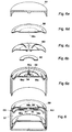
Nachfolgend werden anhand der beiliegenden Zeichnung Ausführungsbeispiele der Erfindung beschrieben. In der Zeichnung zeigt
- die Figur 1 eine Prinzipskizze der erfindungsgemässen Vorrichtung,
- die
Figur 2 eine perspektivische Darstellung einer aufgeschnittenen Crème-Spende-Dose, - die
Figur 3 eine gleichartige Darstellung eines zweiten Ausführungsbeispieles, - die
Figur 4 eine gleichartige Darstellung eines dritten Ausführungsbeispieles, - die
Figur 5 eine gleichartige Darstellung eines vierten Ausführungsbeispieles, deren Einzelteile in den Figuren 5a, 5b, 5c, 5d dargestellt sind, - die
Figur 6 eine gleichartige Darstellung eines fünften Ausführungsbeispiels, deren Einzelteile in denFiguren 6a, 6b, 6c, 6d und 6e dargestellt sind, und - die
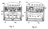
Figuren 7 und 8 zwei weitere Ausführungsbeispiele.
- 1 shows a schematic diagram of the device according to the invention,
- FIG. 2 shows a perspective illustration of a cut cream donation box,
- FIG. 3 shows a similar representation of a second exemplary embodiment,
- FIG. 4 shows a similar representation of a third exemplary embodiment,
- 5 shows a similar representation of a fourth exemplary embodiment, the individual parts of which are shown in FIGS. 5a, 5b, 5c, 5d,
- 6 shows a similar representation of a fifth exemplary embodiment, the individual parts of which are shown in FIGS. 6a, 6b, 6c, 6d and 6e, and
- Figures 7 and 8 two further embodiments.
Wie man aus der Figur 1 entnehmen kann, besteht die erfindungsgemässe Dose im wesentlichen aus dem Dosenboden 1, der eine Lufteintrittsöffnung 1a aufweist, der Dosenwandung 2, dem als ganzes mit 3 bezeichneten Dosenabschluss sowie dem innerhalb der Dose axial verschiebbaren Kolben 4. Der Dosenabschluss 3 enthält einen Zwischenspeicher, dessen Raum mit 5 bezeichnet ist. Er ist unten, also gegen das Behälterinnere 7, durch den steifen Abschlussboden 6 begrenzt und oben, also gegen aussen, durch die elastische Membran 8. Sowohl der Abschlussboden 6 des Zwischenspeichers wie auch die Membran 8 sind auf irgend eine in der Zeichnung nicht dargestellte Art und Weise mit der Wandung 2 fest verbunden. Der Abschlussboden 6 ist mit einer Eintrittsöffnung 6a versehen, die zusammen mit der Klappe 10 ein Eintrittsventil bildet. Diese Klappe kann aus weichem oder steifem Material bestehen. Sie muss irgendwie so angeordnet sein, dass sie sich stets oberhalb der Eintrittsöffnung 6a befindet und dass sie diese freigibt, wenn im Raum 5 ein Sog entsteht, sie aber verschliesst, wenn in diesem Raum ein Druck aufgebaut wird. Auf dem Abschlussboden 6 steht ein Stift 9, der mit ihm fest verbunden sein kann. Die Membran 8 ist mit einer Öffnung 8a versehen, die mit ihrem ganzen Rand auf dem Stift 9 aufliegt. Die Membran ist so ausgebildet, dass sie sich zwar durch einen Druck von aussen elastisch etwas nach innen verformen lässt, aber beim Nachlassen dieses zusätzlichen Druckes sofort wieder ihre ursprüngliche Form annimmt.As can be seen from Figure 1, there is The can according to the invention essentially consists of the can base 1, which has an air inlet opening 1 a, the
Vor dem Verschliessen der Dose wird sowohl der Behälterinnenraum 7, wie auch der Raum 5 des Zwischenspeichers mit dem pastösen Produkt gefüllt. Bei der Benützung des Creme-Spenders wird durch Druck auf die Membran 8 das Volumen des Zwischenspeichers 5 verkleinert, so dass der pastöse Inhalt die Membran nach aussen wölbt, so dass sie dort angehoben wird, wo sie auf dem Stift 9 aufliegt. Dadurch kann vom Inhalt etwas durch die Öffnung 8a auf die Oberseite der Membran austreten, von wo es sich mit dem Finger wegstreichen und verwenden lässt. Sobald der Druck auf die Membran 8 wieder nachlässt, nimmt der Raum 5 sein ursprüngliches Volumen wieder ein. Dadurch wird pastöse Masse aus dem Raum 7 in den Raum 5 nachgesogen. Jedes Mal, wenn etwas Masse aus dem Behälterinnern 7 durch die Öffnung 6a austritt, wird der verschiebbare Kolben 4 entsprechend nach oben gezogen, bis der Raum 7 völlig geleert ist und der Kolben 4 am Abschlussboden 6 ansteht.Before the can is closed, both the
Diese rein schematisch dargestellte Erfindung lässt sich nun auf verschiedene Art und Weise konstruktiv ausgestalten. Ein erstes Ausführungsbeispiel ist in der Figur 2 dargestellt. Hier bestehen, wie man ohne weiteres ersehen kann, die Dosenwandung 12 und der Abschlussboden 16 des Dosenabschlusses aus einem einzigen Werkstück. In der Mitte des Abschlussbodens 16 ist ein Stift 19 ausgebildet, auf welchem die Membran 18 aufliegt, die in ihrer Mitte mit einer Öffnung 18a versehen und an ihrem kreisförmigen Rand mit dem Rand 16b des Abschlussbodens 16 fest verbunden ist. Auf diese Art und Weise begrenzen die Membran 18 und der Abschlussboden 16 einen Zwischenspeicher 15, der über eine Öffnung 16a mit dem Raum 17, also dem Doseninnern verbunden ist, wobei eine an der Membran 18 angelenkte Klappe 20 so ausgebildet ist, dass der Inhalt aus dem Raum 17 in den Zwischenspeicher 15 entweichen, aber nichts aus dem Zwischenspeicher 15 in den Raum 17 zurück gelangen kann. Durch die Form des Randes 18b der Membran 18 ist sichergestellt, dass sich die Membran durch einen äusseren Druck elastisch gegen den Abschlussboden 16 hin verformen lässt und dass sie beim Aufhören einer solchen äusseren Belastung die ursprüngliche Form wieder annimmt, wobei jeweils eine Pumpwirkung entsteht. Beim Herstellen der gefüllten Dose wird zuerst die Membran 18 fest mit dem Abschlussboden 16 des Zwischenspeichers 15 verbunden. Dann wird der Raum 17 mit der Paste gefüllt und zwar so, dass die Paste auch in den Zwischenspeicher 15 eintritt und diesen vollständig füllt. Dann wird der Kolben 14 eingesetzt, wobei das Einsetzen dieses Kolbens auch dazu benützt werden kann, um Paste aus dem Raum 17 in den Zwischenspeicher 15 zu fördern. Nachher wird der mit einer Lufteintrittsöffnung 11a versehene Dosenboden 11 auf die Wandung 12 aufgesetzt, an welcher er beispielsweise mittels einer Schnappverbindung festgehalten wird. Er kann allerdings je nach Materialwahl auch durch Schweissen oder Kleben mit der Dosenwandung 12 unlösbar verbunden werden. Zum Abschluss wird der dem Schutz der Membran 18 dienende Deckel 13 aufgesetzt.This purely schematically illustrated invention can now be designed constructively in various ways. A first exemplary embodiment is shown in FIG. 2. Here, as can be easily seen, the can wall 12 and the
Zum Entnehmen der Paste aus dieser Dose wird nun nach dem Abheben des Deckels 13 die Membran 18 an einer nicht auf dem Stift 19 aufliegenden Stelle gedrückt und dann wieder losgelassen, was die erwartete Pumpwirkung zur Folge hat: Beim Drücken entweicht Paste aus dem Zwischenspeicher 15 durch die Öffnung 18a auf die Oberseite der Membran 18. Sobald die Druckwirkung aufhört, kehrt die Membran in die ursprüngliche Stellung zurück, wodurch sich der Zwischenspeicher wieder vergrössert, so dass Paste aus dem Raum 17 nachgesogen wird, was sich so oft wiederholen lässt, bis der Raum 17 leer ist und der Kolben 14 am Abschlussboden 16 ansteht. Bei Nichtgebrauch lässt sich die Membran 18 wieder durch den Deckel 13 überdecken.To remove the paste from this can, after the
Ein zweites Ausführungsbeispiel ist in der Figur 3 dargestellt. Hier bestehen die Dosenwandung 22 und der mit einem Luftloch 21a versehene Dosenboden 21 aus einem einzigen Werkstück, während der Abschlussboden 26 des Zwischenspeichers 25 von oben eingesetzt wird und durch eine Schnapp- oder Klebverbindung an der Wandung 22 festgehalten wird. Der obere Abschluss des Zwischenspeichers 25 wird auch hier durch eine auf dem oberen Rand der Wandung 22 aufgeklebte und mit ihrer Öffnung 28a frei auf dem Stift 29 aufliegende Membran gebildet, die mit 28 bezeichnet ist. Der Abschlussboden 26 kann, wie das aus der Zeichnung ersichtlich ist, mit dem Stift 29 ein einziges Werkstück bilden. Dieser Abschlussboden ist des weiteren mit einer elastischen Zunge 26b versehen, die auf der Unterseite der Membran 28 anliegt und deren freies Ende sich ganz in der Nähe des Randes der Membran 28 befindet. Eine Öffnung 26c in dieser Zunge 26b dient dazu, dass der elastische Halter 30a den Ventildeckel 30 zum Verschliessen der Eintrittsöffnung 26a elastisch mit der Membran 28 verbinden kann. Ein Deckel 23 dient bei Nichtgebrauch dazu, die Membran 28 gegen Berührung zu schützen. Der Kolben 24, der bei gefüllter Dose mit einem Abstützring auf dem Dosenboden aufsteht, hat bei diesem Ausführungsbeispiel einen verhältnismässig steifen Rand 24a, der durch eine Rollmembran 24b mit dem ebenfalls steifen Mittelteil verbunden ist, wodurch sich eine gute Ausnützung des Dosenvolumens ergibt. Hier wird bei der Herstellung der gefüllten Dose zuerst der Kolben 24 in das aus Wandung 22 und Dosenboden 21 bestehende Gebilde eingelegt. Dann wird die Paste eingefüllt und anschliessend wird der Abschlussboden 26 mit der elastischen Zunge 26b eingesetzt, worauf die Membran 28 aufgesetzt und befestigt wird, die dann ihrerseits durch den zum Gebrauch leicht abnehmbaren Deckel geschützt wird. Wenn der Deckel 23 weggenommen ist, kann man auf die Zunge 26b drücken, wodurch der Speicherraum verkleinert und Paste durch die Öffnung 28a ausgepresst wird. Wird die Zunge 26b wieder losgelassen, so vergrössert sich der Speicherraum 25 wieder, was zur Folge hat, dass Paste durch die Öffnung 26a eintritt. Selbstverständlich kann sowohl bei diesem Ausführungsbeispiel, wie auch bei allen anderen Ausführungsbeispielen der hier mit 29 bezeichnete Stift, der zusammen mit der Öffnung 28a das Auslassventil bildet, ein verjüngtes, in die Öffnung 28a hineinragendes Ende aufweisen, also ein Ende, dass entweder zugespitzt oder abgestuft oder anderswie verjüngt ist. Dadurch wird verhindert, dass nach dem Entnehmen von Paste ein Pastrest in der Öffnung 28a zurückbleiben und dort erhärten kann.A second exemplary embodiment is shown in FIG. 3. Here, the
Das in der Figur 4 dargestellte dritte Ausführungsbeispiel weist eine gewisse Übereinstimmung mit dem anhand der Figur 2 beschriebenen Ausführungsbeispiel auf: Auch hier bestehen die Dosenwandung 32 und der Abschlussboden 36 des Zwischenspeichers 35 aus einem einzigen Werkstück, während der mit einer Öffnung 31a versehene Dosenboden 31 nach dem Einfüllen der Paste und dem Einsetzen des Kolbens 34 aufgesetzt wird. Ein Unterschied besteht darin, dass der Stift 39 und die auf ihm aufliegende Öffnung 38a der Membran 38 ausserhalb der Dosenmitte angeordnet sind. Der andere Unterschied ergibt sich daraus, dass die Membran 38 teilweise mit einer Verstärkung 38b und am Rand mit einer Wellung 38c versehen ist, sodass sie sich eher in der Art einer Federzunge eindrücken lässt. Da im übrigen die Konstruktion und die Arbeitsweise im wesentlichen gleich sind, erübrigt sich deren detaillierte Beschreibung, sowie auch die Beschreibung, wie eine gefüllte Dose hergestellt wird.The third embodiment shown in Figure 4 has a certain correspondence with the exemplary embodiment described with reference to FIG. 2: here too, the can wall 32 and the
Auch bei dem in der Figur 5 und den Einzelzeichnungen 5a, 5b, 5c, 5d dargestellten, vierten Ausführungsbeispiel bestehen die Dosenwandung 42 und der mit einer Öffnung 46a versehene Abschlussboden 46 des Zwischenspeichers aus einem einzigen Werkstück. Der Dosenboden 41 mit der Lufteintrittsöffnung 41a und der mit 44 bezeichnete verschiebbare Kolben sowie der Deckel 43 gleichen den entsprechenden Teilen in den bereits anhand der Figuren 2 und 4 beschriebenen Ausführungsformen. Der Zwischenspeicher 45 wird hier nicht nur durch die Membran 48 und den Abschlussboden 46 sondern zu einem nicht unwesentlichen Teil auch durch eine Zwischenwand begrenzt, die zwei geradlinige Abschnitte 46b (von denen in der Zeichnung nur einer ersichtbar ist!) sowie einen den Stift 49 ringförmig umgebenden Abschnitt 46c aufweist und mit dem Abschlussboden 46 aus einem Werkstück besteht. Innerhalb des ringförmigen Abschnittes 46c ist ein Zylinder 141 angeordnet, der mit einem zwischen den beiden geradlinigen Wandabschnitten 46b angeordneten Federstreifen 142 und einem Federarm 143 versehen ist, welch letzterer mit seinem Ende den Ventildeckel 50 elastisch auf die Öffnung 46a drückt, während der Federstreifen 142 dazu dient, die Membran 48, die eingedrückt wurde, um die Pastenausgabe durch die Öffnung 48a zu bewirken, wieder in die ursprüngliche Lage zurückzuführen. Auch hier dient ein Deckel 43 dazu, die Membran bei Nichtgebrauch gegen jegliche Druckeinwirkung zu schützen.Also in the fourth exemplary embodiment shown in FIG. 5 and the individual drawings 5a, 5b, 5c, 5d, the can wall 42 and the
Ein fünftes Ausführungsbeispiel ist in den Figuren 6, sowie 6a bis 6e dargestellt. Hier ist zwischen dem Abschlussboden 56 des Zwischenspeichers 55, der in der Mitte mit einem Stift 59 und mit einigen um diesen Stift 59 herum angeordneten Öffnungen 56a versehen ist, und der Membran 58 eine mehrfach geschlitzte Tellerfeder 150 eingelegt, die zwischen dem Stift 59 und den Öffnungen 56a auf dem Abschlussboden 56 aufliegt. Bei Verwendung einer derartigen Feder kann die mit einer zentralen Öffnung 58a versehene Membran 58 aus sozusagen beliebig weichem Material bestehen. Auf den Öffnungen 56a liegt der als Ventilteller wirkende Ring 60. Selbstverständlich lässt sich auch dieses Ausführungsbeispiel genau gleich benützen wie die vorstehend beschriebenen Ausführungsbeispiele: Durch Druck auf die Membran 58, die sich bei Nichtgebrauch durch den Deckel 53 schützen lässt, wird entgegen der Kraft der Feder 150 der Zwischenspeicher 55 verkleinert, so dass die in diesem Raum vorhandene Paste einerseits den Ring 60 auf die Öffnungen 56a drückt und diese dadurch verschliesst, und andererseits die Membran 58 in der Mitte anhebt, dadurch das durch den Stift 59 und die Öffnung 58a gebildete Ventil öffnet und dort austritt. Sobald der äussere Druck aufhört, wird die Feder 150 wieder ihre ursprüngliche Stellung einnehmen, so dass auch der Zwischenspeicher 55 seine ursprüngliche Grösse wieder erhält, was zur Folge hat, dass Paste aus dem Doseninneren 57 durch die Öffnungen 56a nachströmen kann, wie das von den bereits beschriebenen Ausführungsbeispielen bekannt ist.A fifth exemplary embodiment is shown in FIGS. 6 and 6a to 6e. Here, between the
Ein weiteres Ausführungsbeispiel ist in der Figur 7 dargestellt. Auch hier bestehen die mit 62 bezeichnete Wandung der Dose und der mit 66 bezeichnete Abschlussboden aus einem einzigen Werkstück, wobei der Abschlussboden durch eine Säule 66b auf dem mit einer Lufteinlassöffnung 61a versehenen Dosenboden 61 abgestützt ist, der seinerseits unlösbar oder schwer lösbar auf dem untersten Rand der Wandung 62 sitzt. Hier ist der Kolben 64 mit einer zentralen Führungshülse 64a versehen, damit er aus seiner untersten Stellung, in welcher er in der Figur 7 dargestellt ist, schrittweise in die oberste Lage gelangen kann, ohne dass die Gefahr des Kippens besteht. Zwei oder mehr Bohrungen 66a im Abschlussboden 66 verbinden den Raum 67 mit dem Zwischenspeicher 65, wobei eine elastische Manschette 70 so als Ventilteller wirkt, dass zwar Paste aus dem Raum 67 durch die Bohrungen 66a in den Zwischenspeicher 65 gelangen kann, das Umgekehrte aber verhindert wird. Der zentrale Stift 69 ist hier über eine als Halterung dienende Membran 69a mit dem Abschlussboden 66 so verbunden, dass er bei einer Verkleinerung des Zwischenspeichers 65 infolge seiner nach unten ausweichenden Halterung 69a nach unten geführt wird und dadurch die Öffnung 68a im Deckel 68 freigibt. Dieser Deckel ist durch einzelne Stege starr mit dem Abschlussboden 66 verbunden. Zur Verkleinerung des Zwischenspeichervolumens lässt sich ein ringförmiger Streifen 68b aus elastischem Material entgegen der Kraft einer Feder 68c gegen den Abschlussboden 66 hin drücken. Auch hier entspricht natürlich die Wirkungsweise der Wirkungsweise, wie sie vorstehend anhand der Prinzipskizze der Figur 1 beschrieben ist, mit dem Unterschied, dass zur Ausgabe der Paste nicht ein Druck auf die elastische Membran sondern auf den elastisch gelagerten Ring 68b auszuüben ist. Ein Deckel 63 dient dazu, die Membran vor unbeabsichtigter Betätigung zu schützen.Another exemplary embodiment is shown in FIG. Here, too, the wall of the can, designated by 62, and the end floor, designated by 66, consist of a single workpiece, the end floor being supported by a
Das in der Figur 8 dargestellte, letzte Ausführungsbeispiel unterscheidet sich vom vorstehend beschriebenenen Ausführungsbeispiel nicht so sehr dadurch, dass der hier mit 79 bezeichnete elastisch gelagerte Stift den mit einer Öffnung 78a versehenen Deckel 78 nicht in seiner Mitte sondern an einer anderen Stelle verschliesst, sondern viel mehr dadurch, dass der Deckel 78 mit einem relativ zu ihm verschiebbaren und durch eine Feder 78c abgestützen Einsatz 78d versehen ist. Durch Hinunterdrücken dieses Einsatzes 78d wird der durch den Abschlussboden 76 und den Deckel 78 begrenzte Zwischenspeicher 75 verkleinert, so dass die Paste aus diesem Raum durch die Öffnung 78a solange entweichen kann, bis sich der durch das Drücken des Einsatzes 78d erzeugte Überdruck abgebaut hat und der durch die Membran 79a elastisch gelagerte Stift wieder die in der Zeichnung dargestellte Lage eingenommen hat. Beim Loslassen des Einsatzes 78d entsteht durch die Wirkung der Feder 78c im Zwischenspeicher 75 ein Unterdruck, der nicht nur das Schliessen der Öffnung 78a im Deckel 78 zur Folge hat, sondern auch das Nachströmen von Paste durch die Bohrung 76a, die auf der Zwischenspeicherseite durch eine dem Druck aus dem Raum 77 nachgebende, als Ventilklappe wirkende Manschette 80 abgedeckt ist. Auch hier bewegt sich beim Entweichen der Luft aus dem Raum 77 der mit 74 bezeichnete Kolben nach oben, da ja Luft durch die Öffnung 71a im Boden 71 nachströmen kann. Ein Deckel 73 dient dazu den Einsatz 78d bei Nichtgebrauch zu schützen.The last exemplary embodiment shown in FIG. 8 differs from the exemplary embodiment described above not so much by the fact that the elastically mounted pin, designated here by 79, does not close the cover 78 provided with an opening 78a in the middle but at another location, but much more so that the cover 78 is displaceable relative to and through it a spring 78c supported insert 78d is provided. By pressing this insert 78d down, the
Claims (8)
- Container constructed as dispenser for pasty products and with an air entry opening (1a) in the container base (1), an axially displaceable piston (4), which is arranged therebehind and separates the pasty product from the container base (1), and a container closure (3), which is arranged opposite the container base (1) and contains an intermediate store (5) with an inlet valve (6a, 10) freeing the inlet of the pasty product from the interior of the container and an outlet valve (8a, 9) enabling the exit of the pasty product from the container as well as an elastic part serving for the reversible diminishing of the intermediate store, wherein the outlet valve is formed by a flat closure organ (8), which closes the intermediate store off outwardly and is provided with a hole (8a) serving as exit opening, and a pin (9), which is arranged in the intermediate store (5) and on which the exit opening (8a) of the closure organ (8) lies by its rim, characterised thereby, that the intermediate store displays a volume which is not reducible to zero and that the valves are non-return valves actuable by the product in the intermediate store, wherein either the closure organ is constructed as elastic diaphragm of the part for diminishing the intermediate store or the pin (9) is borne elastically.
- Container according to claim 1, characterised thereby, that the free end of the pin (9) is tapered and projects into the exit opening (8a).
- Container according to claim 1, characterised thereby, that the free end of the pin is stepped in such a manner that the cross-section of the end portion corresponds to the cross-section of the exit opening made in the diaphragm and its height corresponds to the thickness of the diaphragm.
- Container according to one of the claims 1 to 3, in which the inlet valve is made in the base of the intermediate store, characterised thereby, that it is formed by an opening in the base and a diaphragm which is lying thereover, is secured against lateral displacement and serves as valve flap.
- Container according to one of the claims 1 to 3, in which the inlet valve is made in the base of the intermediate store, characterised thereby, that it is formed by an opening in this base and a valve plate which is fastened or shaped on at the portion of the diaphragm serving for the reversible diminishing of the intermediate store.
- Container with an elastic diaphragm serving as closure organ according to one of the claims 1 to 5, characterised thereby, that the diaphragm is provided with at least one stiffened portion effecting the construction as pump lever and with elastic regions which adjoin thereat and enable the intermediate store to be diminished by pressure on the pump lever and which return the pump lever into the initial setting on disappearance of an external pressure.
- Container with a diaphragm serving as closure organ according to one of the claims 1 to 5, characterised thereby, that a spring is arranged under the diaphragm.
- Container according to claim 1 with an elastically borne pin (69, 79), characterised by a spring-loaded piston or ring for diminishing the intermediate store.
Priority Applications (1)
| Application Number | Priority Date | Filing Date | Title |
|---|---|---|---|
| AT89810070T ATE86576T1 (en) | 1988-10-03 | 1989-01-26 | CAN TRAINED AS DISPENSER FOR PASTOESE PRODUCTS. |
Applications Claiming Priority (2)
| Application Number | Priority Date | Filing Date | Title |
|---|---|---|---|
| CH366388 | 1988-10-03 | ||
| CH3663/88 | 1988-10-03 |
Publications (2)
| Publication Number | Publication Date |
|---|---|
| EP0363307A1 EP0363307A1 (en) | 1990-04-11 |
| EP0363307B1 true EP0363307B1 (en) | 1993-03-10 |
Family
ID=4260838
Family Applications (1)
| Application Number | Title | Priority Date | Filing Date |
|---|---|---|---|
| EP89810070A Expired - Lifetime EP0363307B1 (en) | 1988-10-03 | 1989-01-26 | Dispensing container for viscous products |
Country Status (4)
| Country | Link |
|---|---|
| EP (1) | EP0363307B1 (en) |
| AT (1) | ATE86576T1 (en) |
| DE (1) | DE58903718D1 (en) |
| ES (1) | ES2039089T3 (en) |
Families Citing this family (12)
| Publication number | Priority date | Publication date | Assignee | Title |
|---|---|---|---|---|
| DE59104114D1 (en) * | 1990-04-09 | 1995-02-16 | Lir France Sa | Pump device for a flowable, in particular pasty and / or liquid product and dispenser with such a pump device. |
| DE9215129U1 (en) * | 1992-11-06 | 1993-01-07 | Teroson Gmbh, 6900 Heidelberg, De | |
| IT1256628B (en) * | 1992-12-04 | 1995-12-12 | DISPENSER OF FLUID SUBSTANCES, WITH DEFORMABLE HEAD | |
| IT1298131B1 (en) | 1998-01-15 | 1999-12-20 | Capsol S P A Stampaggio Resine | DISPENSER OF PASTOSE OR CREAMY SUBSTANCES |
| EP0990594A1 (en) * | 1998-09-23 | 2000-04-05 | Guala Dispensing S.P.A. | Device for dispensing pasty products |
| GB0603416D0 (en) * | 2006-02-20 | 2006-03-29 | Rieke Corp | Dispensers e.g. for cosmetics |
| KR101028988B1 (en) * | 2009-03-31 | 2011-04-12 | 주식회사 탭코리아 | A airless pump have cream cosmetic case |
| FR2997934B1 (en) * | 2012-11-12 | 2015-06-19 | Aptar France Sas | FLUID PRODUCT TANK. |
| DE102013214231B3 (en) | 2013-07-19 | 2014-11-06 | Aptar Radolfzell Gmbh | Discharge head and dispenser for a preferably pasty medium |
| KR101453048B1 (en) * | 2013-12-12 | 2014-10-23 | (주)연우 | A cosmetic case of cream type |
| KR101627227B1 (en) * | 2014-12-02 | 2016-06-03 | (주)연우 | The Sealing structure of cream type cosmetic case |
| AU2016270010A1 (en) | 2015-05-29 | 2017-11-30 | Colgate-Palmolive Company | Neat hand-washing system |
Family Cites Families (6)
| Publication number | Priority date | Publication date | Assignee | Title |
|---|---|---|---|---|
| US3361305A (en) * | 1966-06-27 | 1968-01-02 | Walter B. Spatz | Dispenser for fluent masses |
| US3752366A (en) * | 1971-10-27 | 1973-08-14 | W Lawrence | Two-piece suction pump |
| FR2566746B1 (en) * | 1984-06-29 | 1986-10-31 | Aerosol Inventions Dev | DEVICE FOR DEPOSITING A SIDE PASTE OF A PASTY SUBSTANCE ON A PASTE CORD. |
| FR2585439B1 (en) * | 1985-07-24 | 1988-01-08 | Cebal | DISPENSING HEAD FOR CREAMY OR PASTY PRODUCTS |
| DE3636013A1 (en) * | 1986-10-23 | 1988-05-05 | Henkel Kgaa | DISPENSER FOR PASTE-LIKE PRODUCT |
| DE3708713A1 (en) * | 1987-03-18 | 1988-09-29 | Bramlage Gmbh | MEASURE DONOR FOR PASTOESE |
-
1989
- 1989-01-26 AT AT89810070T patent/ATE86576T1/en active
- 1989-01-26 ES ES198989810070T patent/ES2039089T3/en not_active Expired - Lifetime
- 1989-01-26 DE DE8989810070T patent/DE58903718D1/en not_active Expired - Fee Related
- 1989-01-26 EP EP89810070A patent/EP0363307B1/en not_active Expired - Lifetime
Also Published As
| Publication number | Publication date |
|---|---|
| DE58903718D1 (en) | 1993-04-15 |
| ES2039089T3 (en) | 1993-08-16 |
| EP0363307A1 (en) | 1990-04-11 |
| ATE86576T1 (en) | 1993-03-15 |
Similar Documents
| Publication | Publication Date | Title |
|---|---|---|
| EP0013691B1 (en) | Dispenser for pasty products | |
| EP0452260B1 (en) | Pumping device for a fluid product, particularly liquid or pasty, and dispenser for such a device | |
| DE60132155T2 (en) | Container with riser and applicator | |
| EP0363307B1 (en) | Dispensing container for viscous products | |
| EP3010827B1 (en) | Dispenser for liquids | |
| EP0599301A1 (en) | Device for metered dispensing of flowable product from a container | |
| DE3802682C2 (en) | Liquid dispenser | |
| DE60115183T2 (en) | Pen, in particular for a cream, gel or paste-like product | |
| DE60320607T2 (en) | Unit for packaging and dispensing a product, in particular in the form of a sample | |
| EP0230252A2 (en) | Dispenser for viscous products | |
| CH644678A5 (en) | DISPENSER VALVE, ESPECIALLY FOR VISCOSE PRODUCTS. | |
| DE3347629C2 (en) | ||
| DE1475174A1 (en) | Liquid spray device | |
| DE2900094A1 (en) | ACTUATING DEVICE FOR A PUMP ACTUABLE BY FINGERPRESSURE | |
| DE1473169A1 (en) | Valve for dispensing measured amounts of a pressurized fluid | |
| CH665344A5 (en) | HYDRAULICALLY CONTROLLED DOSAGE DISPENSER FOR LIQUID TO PASTOISE MEDIUM. | |
| DE2618202A1 (en) | DISPENSER DEVICE FOR SUBSTANCES FOR BODY HYGIENE | |
| DE1951696C3 (en) | Device on apparatus for the portion-wise removal of liquid or pasty products from a container | |
| EP1332798A2 (en) | Dispenser for fluid or pasty products | |
| DE3235171A1 (en) | DONORS, ESPECIALLY FOR PASTOESES GOOD | |
| CH679912A5 (en) | ||
| DE60217276T2 (en) | Device for packaging and dispensing a liquid product | |
| DE602004010660T2 (en) | IMPROVEMENTS RELATING TO TRANSFER DEVICE | |
| DE3101020C2 (en) | Portion dispenser for liquid medium z. B. Soap | |
| CH660953A5 (en) | DEVICE FOR DELIVERING LIQUID OR PASTOUS PRODUCTS. |
Legal Events
| Date | Code | Title | Description |
|---|---|---|---|
| PUAI | Public reference made under article 153(3) epc to a published international application that has entered the european phase |
Free format text: ORIGINAL CODE: 0009012 |
|
| AK | Designated contracting states |
Kind code of ref document: A1 Designated state(s): AT BE CH DE ES FR GB GR IT LI LU NL SE |
|
| 17P | Request for examination filed |
Effective date: 19900301 |
|
| 17Q | First examination report despatched |
Effective date: 19910516 |
|
| RAP1 | Party data changed (applicant data changed or rights of an application transferred) |
Owner name: COMPAGNIE FRANCAISE DES MATIERES PLASTIQUES PLASCO |
|
| GRAA | (expected) grant |
Free format text: ORIGINAL CODE: 0009210 |
|
| AK | Designated contracting states |
Kind code of ref document: B1 Designated state(s): AT BE CH DE ES FR GB GR IT LI LU NL SE |
|
| PG25 | Lapsed in a contracting state [announced via postgrant information from national office to epo] |
Ref country code: SE Effective date: 19930310 Ref country code: NL Effective date: 19930310 Ref country code: GR Free format text: LAPSE BECAUSE OF FAILURE TO SUBMIT A TRANSLATION OF THE DESCRIPTION OR TO PAY THE FEE WITHIN THE PRESCRIBED TIME-LIMIT Effective date: 19930310 Ref country code: BE Effective date: 19930310 |
|
| REF | Corresponds to: |
Ref document number: 86576 Country of ref document: AT Date of ref document: 19930315 Kind code of ref document: T |
|
| REF | Corresponds to: |
Ref document number: 58903718 Country of ref document: DE Date of ref document: 19930415 |
|
| RAP2 | Party data changed (patent owner data changed or rights of a patent transferred) |
Owner name: PLASCO SA |
|
| REG | Reference to a national code |
Ref country code: CH Ref legal event code: PUE Owner name: PLASCO S.A. |
|
| GBT | Gb: translation of ep patent filed (gb section 77(6)(a)/1977) |
Effective date: 19930420 |
|
| ET | Fr: translation filed | ||
| ITF | It: translation for a ep patent filed |
Owner name: MODIANO & ASSOCIATI S.R.L. |
|
| NLV1 | Nl: lapsed or annulled due to failure to fulfill the requirements of art. 29p and 29m of the patents act | ||
| REG | Reference to a national code |
Ref country code: FR Ref legal event code: TP |
|
| PGFP | Annual fee paid to national office [announced via postgrant information from national office to epo] |
Ref country code: CH Payment date: 19940112 Year of fee payment: 6 |
|
| PLBE | No opposition filed within time limit |
Free format text: ORIGINAL CODE: 0009261 |
|
| STAA | Information on the status of an ep patent application or granted ep patent |
Free format text: STATUS: NO OPPOSITION FILED WITHIN TIME LIMIT |
|
| PGFP | Annual fee paid to national office [announced via postgrant information from national office to epo] |
Ref country code: AT Payment date: 19940120 Year of fee payment: 6 |
|
| PG25 | Lapsed in a contracting state [announced via postgrant information from national office to epo] |
Ref country code: LU Free format text: LAPSE BECAUSE OF NON-PAYMENT OF DUE FEES Effective date: 19940131 |
|
| 26N | No opposition filed | ||
| PG25 | Lapsed in a contracting state [announced via postgrant information from national office to epo] |
Ref country code: AT Effective date: 19950126 |
|
| PG25 | Lapsed in a contracting state [announced via postgrant information from national office to epo] |
Ref country code: LI Effective date: 19950131 Ref country code: CH Effective date: 19950131 |
|
| ITPR | It: changes in ownership of a european patent |
Owner name: CESSIONE;LIR FRANCE |
|
| REG | Reference to a national code |
Ref country code: FR Ref legal event code: TP |
|
| REG | Reference to a national code |
Ref country code: GB Ref legal event code: 732E |
|
| REG | Reference to a national code |
Ref country code: ES Ref legal event code: PC2A Owner name: LIR FRANCE |
|
| REG | Reference to a national code |
Ref country code: CH Ref legal event code: PL |
|
| PGFP | Annual fee paid to national office [announced via postgrant information from national office to epo] |
Ref country code: DE Payment date: 20011218 Year of fee payment: 14 |
|
| PGFP | Annual fee paid to national office [announced via postgrant information from national office to epo] |
Ref country code: GB Payment date: 20011219 Year of fee payment: 14 |
|
| REG | Reference to a national code |
Ref country code: GB Ref legal event code: IF02 |
|
| PGFP | Annual fee paid to national office [announced via postgrant information from national office to epo] |
Ref country code: FR Payment date: 20020115 Year of fee payment: 14 |
|
| PGFP | Annual fee paid to national office [announced via postgrant information from national office to epo] |
Ref country code: ES Payment date: 20020116 Year of fee payment: 14 |
|
| PG25 | Lapsed in a contracting state [announced via postgrant information from national office to epo] |
Ref country code: GB Free format text: LAPSE BECAUSE OF NON-PAYMENT OF DUE FEES Effective date: 20030126 |
|
| PG25 | Lapsed in a contracting state [announced via postgrant information from national office to epo] |
Ref country code: ES Free format text: LAPSE BECAUSE OF NON-PAYMENT OF DUE FEES Effective date: 20030127 |
|
| PG25 | Lapsed in a contracting state [announced via postgrant information from national office to epo] |
Ref country code: DE Free format text: LAPSE BECAUSE OF NON-PAYMENT OF DUE FEES Effective date: 20030801 |
|
| GBPC | Gb: european patent ceased through non-payment of renewal fee | ||
| PG25 | Lapsed in a contracting state [announced via postgrant information from national office to epo] |
Ref country code: FR Free format text: LAPSE BECAUSE OF NON-PAYMENT OF DUE FEES Effective date: 20030930 |
|
| REG | Reference to a national code |
Ref country code: FR Ref legal event code: ST |
|
| REG | Reference to a national code |
Ref country code: ES Ref legal event code: FD2A Effective date: 20030127 |
|
| PG25 | Lapsed in a contracting state [announced via postgrant information from national office to epo] |
Ref country code: IT Free format text: LAPSE BECAUSE OF NON-PAYMENT OF DUE FEES;WARNING: LAPSES OF ITALIAN PATENTS WITH EFFECTIVE DATE BEFORE 2007 MAY HAVE OCCURRED AT ANY TIME BEFORE 2007. THE CORRECT EFFECTIVE DATE MAY BE DIFFERENT FROM THE ONE RECORDED. Effective date: 20050126 |