EP0362818A2 - Méthode d'enregistrement par transfert thermique, appareil pour appliquer cette méthode ainsi qu'un appareil de télécopie incorporant un tel appareil - Google Patents
Méthode d'enregistrement par transfert thermique, appareil pour appliquer cette méthode ainsi qu'un appareil de télécopie incorporant un tel appareil Download PDFInfo
- Publication number
- EP0362818A2 EP0362818A2 EP89118404A EP89118404A EP0362818A2 EP 0362818 A2 EP0362818 A2 EP 0362818A2 EP 89118404 A EP89118404 A EP 89118404A EP 89118404 A EP89118404 A EP 89118404A EP 0362818 A2 EP0362818 A2 EP 0362818A2
- Authority
- EP
- European Patent Office
- Prior art keywords
- recording
- ink sheet
- ink
- image
- recording medium
- Prior art date
- Legal status (The legal status is an assumption and is not a legal conclusion. Google has not performed a legal analysis and makes no representation as to the accuracy of the status listed.)
- Granted
Links
Images


Classifications
-
- B—PERFORMING OPERATIONS; TRANSPORTING
- B41—PRINTING; LINING MACHINES; TYPEWRITERS; STAMPS
- B41J—TYPEWRITERS; SELECTIVE PRINTING MECHANISMS, i.e. MECHANISMS PRINTING OTHERWISE THAN FROM A FORME; CORRECTION OF TYPOGRAPHICAL ERRORS
- B41J17/00—Mechanisms for manipulating page-width impression-transfer material, e.g. carbon paper
- B41J17/02—Feeding mechanisms
- B41J17/12—Special adaptations for ensuring maximum life
Definitions
- This invention relates to a heat transfer recording apparatus for transferring the ink of an ink sheet to a recording medium to thereby record images on a recording medium, and a facsimile apparatus.
- heat transfer recording apparatus covers, for example, a facsimile apparatus, an electronic typewriter, a copying apparatus, a printer apparatus, etc.
- a heat transfer printer uses an ink sheet comprising a base film having heat-meltable (or heat-sublimating) ink applied thereto, selectively heats the ink sheet by a thermal head in conformity with an image signal, and transfers the melted (or sublimated) ink to recording sheet to thereby accomplish image recording.
- this ink sheet is such that the ink is completely transferred to the recording paper by one time of image recording (a so-called one time sheet) and therefore, after the termination of recording of one character or one line, it has been necessary to convey the ink sheet by an amount corresponding to the length of the record, and then reliably bring the unused portion of the ink sheet to a recording position. This has increased the quantity of ink sheets used, and there has been the tendency that as compared with the ordinary thermo-sensitive printer which effects recording on thermo-sensitive paper, the running cost of the heat transfer printer becomes high.
- the embodiment which will hereinafter be described is a heat transfer recording apparatus in which the recording interval from the termination of image recording until the next image recording is started is counted by time counting means and the waiting time is determined correspondingly to the recording interval counted by the time counting means and which operates so as to effect the recording of an image on a recording medium when the waiting time elapses after the start of the conveyance of an ink sheet by conveying means for conveying the ink sheet.
- the embodiment is a facsimile apparatus in which during the recording of a received image or an image signal from image input means, the recording interval from the termination of image recording until the next image recording is started is counted by time counting means and the waiting time is determined correspondingly to the recording interval counted by the time counting means and which operates so as to effect the recording of the next image signal on a recording medium when the determined waiting time elapses after the start of the conveyance of an ink sheet by conveying means for conveying the ink sheet.
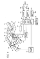
- Figure 1 is a block diagram schematically showing the construction of a heat transfer printer using an embodiment of the present invention as it is applied to a facsimile apparatus
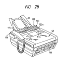
- Figure 2A is a side cross-sectional view of the facsimile apparatus
- Figure 2B is a pictorial perspective view of the facsimile apparatus.
- the reference numeral 100 designates a reading unit for photoelectrically reading an original and outputting it as a digital image signal to a control unit 101, and the reading unit 100 is provided with an original conveying motor, a CCD image sensor, etc.
- the reference numeral 101 designates a control unit for controlling the entire facsimile apparatus, and the control unit 101 codes the image data from the reading unit 100 and transmits it through a modem 106 and an NCU 107.
- the control unit 101 decodes the received coded image data and converts in into image data, and outputs it to a recording unit provided with a thermal head, etc. and reproduces the image data.
- the control unit 101 is provided with a CPU 113 for outputting various control signals in accordance with a control program stored in an ROM 114 and controlling the entire apparatus, an ROM 114 storing therein the control program of the CPU 113 and various data, an RAM 115 for temporarily preserving various data as the working area of the CPU 113, etc.
- the reference numeral 116 designates a timer used to count the time from the termination of the recording of one line until the image data of the next one line is transported to a thermal head 13 and stored therein, as will be described later. This timer 116 is not always necessary, but for example, the time may be counted by software.
- the reference numeral 103 denotes an operation unit including keys for designating various functions such as the start of transmission and telephone number input keys
- the reference character 103a designates a switch for indicating the kind of an ink sheet 14 used. When the switch 103a is ON, it indicates that a multiprint ink sheet has been mounted, and when the switch 103a is OFF, it indicates that an ordinary ink sheet has been mounted.
- the reference numeral 104 denotes an indicating unit usually provided in the operation unit 103 to indicate various functions and the condition of the apparatus.
- the reference numeral 106 designates a modem (modemodulator), and the reference numeral 107 denotes a net control unit (NCU).
- Figure 2A is a side cross-sectional view of a facsimile apparatus
- Figure 2B is a pictorial perspective view of the facsimile apparatus.
- portions common to those in Figure 1 are designated by similar reference numerals.
- the reference numeral 10 designates a roll of paper comprising recording paper 11 which is plain paper would in the form of a roll on a core 10a.
- This roll of paper 10 is rotatably contained so that the recording paper 11 can be supplied to the thermal head 13 by the rotation of a platen roller 12 in the direction of arrow.
- the reference character 10b denotes a loading portion for the roll of paper in which the roll of paper 10 is removably loaded.
- the platen roller 12 conveys the recording paper 11 in the direction of arrow b and also presses the ink sheet 14 and the recording paper 11 between it and the heat generating member 132 of the thermal head 13.
- the recording paper 11 on which image recording has been effected by the heat generation of the thermal head 13 is conveyed toward discharge rollers 16a and 16b by further rotation of the platen roller 12, and is cut into a page unit by the meshing engagement between cutters 15a and 15b and discharged when image recording by one page is terminated.
- the reference numeral 17 denotes an ink sheet supply roll on which the ink sheet 14 is wound.
- the reference numeral 18 designates an ink sheet take-up roll which is driven by an ink sheet conveying motor 25 to convey the ink sheet 14 in the direction opposite to the direction of conveyance of the recording paper 11, i.e., the direction of arrow a .
- the ink sheet supply roll 17 and the ink sheet take-up roll 18 are removably loaded in an ink sheet loading portion 70 within the apparatus body.
- the reference numeral 19 denotes a sensor for detecting the remaining amount of the ink sheet 14 and detecting the conveyance velocity of the ink sheet 14.
- the reference numeral 20 designates an ink sheet sensor for detecting the presence of the ink sheet 14, and the reference numeral 21 denotes a spring which presses the thermal head 13 against the platen roller 12 with the recording paper 11 and the ink sheet 14 interposed therebetween.
- the reference numeral 22 designates a recording paper sensor for detecting the presence of the recording paper.
- the reference numeral 72 denotes a roller for guiding the ink sheet 14.
- the reference numeral 30 designates a light source for illuminating an original 32, and the light reflected by the original 32 is input to a CCD sensor 31 through an optical system (microns 50, 51 and a lens 52) and converted into an electrical signal.
- the original 32 is conveyed correspondingly to the reading speed for the original 32 by conveying rollers 53, 54, 55 and 56 driven by an original conveying motor, not shown.
- the reference numeral 57 denotes an original supporting table, and a plurality of originals 32 supported on this supporting table 57 are separated one by one and conveyed to the reading unit 100 by the cooperation between a conveying roller 54 and a pressing-separating piece 58 while being guided by a slider 57a, and are discharged onto a tray 77 after they are read.
- the reference numeral 41 designates a control base plate constituting the essential portion of the control unit 101, and various control signals are output from this control base plate 41 to various portions of the apparatus.
- the reference numeral 106 denotes a modem base plate unit, and the reference numeral 107 designates an NCU base plate unit.
- a conveying system for the recording paper 11 and the ink sheet 14 in the recording unit is shown in detail in Figure 1.
- the thermal head 13 is a line head which receives as inputs serial recording data corresponding to one line and a latch signal from the control unit 101 by way of a signal line 43 and is driven with a heat generating element which comprises the heat generating resistance member 132 corresponding to one line being divided into a plurality of blocks, thereby effecting the recording of one line.
- the reference nuemral 46 designates a driving circuit which receives as an input a driving signal for the thermal head 13 from the control unit 101 and outputs a strobe signal 44 for driving the thermal head 13 at each block unit.
- the reference numerals 48 and 49 denote motor driving circuits for rotatively driving the corresponding recording paper conveying motor 24 and ink sheet conveying motor 25, respectively.
- the reference numerals 26 and 27 designate transmission gears for transmitting the rotation of the recording paper conveying motor 24 to the platen roller 12, and the reference numerals 28 and 29 denote transmission gears for transmitting the rotation of the ink sheet conveying motor 25 to the take-up roll 18.
- the recording paper conveying motor 24 and the ink sheet conveying motor 25 are stepping motors, whereas this is not restrictive, but they may be, for example, DC motors or the like.
- the directions of conveyance of the recording paper 11 and the ink sheet 14 being thus made opposite to each other, the direction in which images are successively recorded lengthwisely of the recording paper 11 (the direction of arrow a , i.e., the direction opposite to the direction of conveyance of the recording paper 11) and the direction of conveyance of the ink sheet coincide with each other.
- V P the conveyance velocity V P of the recording paper 11
- V P -n ⁇ V I
- V I is a conveyance velocity of the ink sheet 14
- V PI the relative velocity V PI of the recording paper 11 and the ink sheet 14 as viewed from the thermal head 13
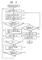
- Figure 3 is a flow chart showing the reception of images corresponding to one page in the facsimile apparatus of the present embodiment and the recording process therefor, and the control program of the CPU 113 which executes this process is stored in the ROM 114 of the control unit 101.
- This process is started by the image reception of the facsimile apparatus.
- a facsimile signal is received at step S1
- the timer 116 is started.
- the received image signal is decoded, and the decoded image data is serially output to the thermal head 13.
- step S4 whether the transportation of the image data for one line to the thermal head 13 has been terminated is examined, and if it is not terminated, whether the image recording process for one page has been terminated is examined at step S5. If the image recording process is not terminated, return is made to the step S2, where the above-described operation is executed, but if the recording process for one page is terminated, advance is made to step S6.
- the time counting by the timer 116 is stopped, and at step S7, the recorded recording paper is cut by the cutter 15 and the cut recording paper is discharged out of the apparatus.
- step S4 when at step S4, the image data for one line is transported to the thermal head 13, advance is made to step S8.
- the ink sheet conveying motor 25 is then driven to convey the ink sheet 14 in the direction of arrow a , whereby the ink sheet 14 is conveyed in the direction of arrow a in Figure 1 by an amount corresponding to 1/n line.
- the recording paper conveying motor 24 is driven to convey the recording paper 11 in the direction of arrow b by an amount corresponding to one line.
- the length corresponding to one line is set to about 1/15.4 mm, and the amounts of conveyance of the recording paper 11 and the ink sheet 14 can be set by changing the energization pulse numbers of the motors 24 and 25, respectively.
- Advance is then made to step S9, where the timer 116 is stopped and the counted value by the timer 116 is read. On the basis of this counted value, the waiting (delay) time is determined, and at step S10, standby is effected for this waiting time.
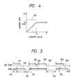
- Figure 4 is a graph showing the relation between the counted value and the waiting time.
- the counted value indicates the time from after the recording of one line until the next recording is started, and in a section indicated by 400 wherein the counted value is up to "To", as the counted value increases, the waiting time likewise increases.
- the waiting time is set so as to be a maximum waiting time T WMAX .
- the waiting time continuously increases substantially in proportion to the increase in the counted value t , but for example, design may be made such that the waiting time increases stepwise relative to the counted value.
- the maximum waiting time T WMAX is 3 [ms] and the counted value To is 30 [ms], whereas this is not restrictive, but they are suitably selected.
- step S11 When the waiting time thus determined elapses, advance is made to step S11, where the thermal head 13 is electrically energized to effect transfer recording.
- the thermal head 13 is divided into a plurality of heat generating element groups (blocks) and is electrically energized in block unit to effect recording and therefore, at step S12, whether the electrical energization of all blocks of the thermal head 13 has been terminated is examined.
- step S12 whether the electrical energization of all blocks of the thermal head 13 has been terminated is examined.
- the timer 116 is started to start the counting of the time till the recording of the next line.
- the movement of the ink sheet 14 when the recording paper 11 is conveyed may be such that as during recording, it is conveyed at a velocity of V P /n in the direction opposite to the direction of conveyance of the recording paper 11, and the value of n may be made greater than that during recording.
- the same movement as that of the recording paper 11 may be effected by the platen roller 12, or the ink sheet may remain stopped instead of being moved.
- the conveyance of the recording paper 11 is effected at the step S8, but alternatively may be effected when the step S11 is started.
- the recording time required per line is about 2.5 ms
- the recording interval is about 0 ⁇ 30 ms
- the waiting time is about 0 ⁇ 2.5 ms.
- Figure 5 shows the conveyance timing for the ink sheet 14 and the recording paper 11 when the aforedescribed control is effected.
- 501 - 504 show the energization time of the ink sheet conveying motor 25 and 505 - 508 show the recording time by the thermal head 13. Also, 510, 511 and 512 show the waiting time. Further, 515 and 516 show the recording interval counted from the recording of one line till the recording of the next one line.
- the waiting time shown by 511 is a waiting time determined on the basis of the recording interval shown by 515.
- the waiting time shown by 512 is a waiting time determined on the basis of the recording interval shown by 516.
- the recording time 507 has little or no recording interval ("0 (zero)") between it and the recording time 506 for the previous line and therefore, with the waiting time as "0" and in subsequence to the recording time 506, the recording of the next line (shown by 507) is started without a waiting time being provided.
- the aforementioned recording interval may also be found by subtracting the required recording time from the recording period.
- Figure 6 shows the image recording condition when image recording is effected with the directions of conveyance of the recording paper 11 and the ink sheet 14 in this embodiment made opposite to each other.
- the recording paper 11 and the ink sheet 14 are nipped between the platen roller 12 and the thermal head 13, and the thermal head 13 is urged against the platen roller 12 with a predetermined pressure by the spring 21.
- the recording paper 11 is conveyed in the direction of arrow b at a velocity V P by the rotation of the platen roller 12.
- the ink sheet 14 is conveyed in the direction of arrow a at a velocity V I by the rotation of the ink sheet conveying motor 25.
- the reference character 14a designates the base film of the ink sheet 14, and the reference character 14b denotes the ink layer of the ink sheet 14.
- the ink of the ink layer 81 heated by the heat generating resistance member 132 being electrically energized melts, and that portion thereof which is designated by 82 is transferred to the recording paper 11.
- This ink layer portion 82 transferred corresponds to approximately 1/n of the ink layer designated by 81.
- this transfer it is necessary to create a shearing force for the ink on the border line of the ink layer 14b and transfer only the ink layer portion 82 to the recording paper 11.
- this shearing force differs depending on the temperature of the ink layer, and tends to become smaller as the temperature of the ink layer becomes higher. So, if the heating time for the ink sheet 14 is shortened, the shearing force in the ink layer becomes greater and therefore, if the relative velocity of the ink sheet 14 and the recording paper 11 is made greater, the ink layer to be transferred can be reliably peeled from the ink sheet 14.
- the heating time of the thermal head 13 in the facsimile apparatus is as short as about 0.6 ms and therefore, by making the direction of conveyance of the ink sheet 14 and the direction of conveyance of the recording paper 11 opposite to each other, the relative velocity of the ink sheet 14 and the recording paper 11 is increased.
- this embodiment has been described with respect to the case where the directions of conveyance of the recording paper 11 and the ink sheet 14 during recording are opposite to each other, whereas this is not restrictive, but the present invention is also applicable to a case where the recording paper and the ink sheet are conveyed in the same direction and recording is effected.
- Figure 7 is a cross-sectional view of the ink sheet used in the multiprint of the present embodiment, and this ink sheet is constructed of four layers.
- a second layer is a base film which provides a support for the ink sheet 14.
- the base film may advantageously be an aromatic polyamide film of high heat resistance or condenser paper, but the conventional polyester film will also stand use.
- the thickness of this layer should advantageously be as small as possible in respect of the quality of printing, from the viewpoint of its role as a medium, but may desirably be 3 - 8 ⁇ m in respect of strength.
- a third layer is an ink layer containing therein an amount of ink capable of being transferred to the recording paper (recording sheet) n times.
- the chief components of this layer are resin such as EVA as an adhesive agent, carbon black or nigrosine dye for coloring, and carnauba wax or paraffin wax as a binding material, and these are combined so as to stand n times of use in the same portion.
- the amount of application of these materials may desirably be 4 - 8 g/m2, but can be selected arbitrarily because sensitivity and concentration differ depending on the amount of application.
- a fourth layer is a top coating layer for preventing the ink of the third layer from being pressure-transferred to the recording paper in the portion thereof which should not be printed, and is composed of transparent wax or the like. Thus, it is only the transparent fourth layer that is pressure-transferred, and the ground of the recording paper can be prevented from being stained.
- a first layer is a heat resisting coat layer for protecting the base film which is the second layer from the heat of the thermal head 13. This is suitable for multiprint having the possibility of heat energy for n lines being applied to the same portion (when black information is continuous), but whether this layer should be used or not can be suitably chosen. Also, this is effective for a base film of relatively low heat resistance such as a polyester film.
- the ink sheet 14 may comprise, for example, a base layer and a porous ink retaining layer provided on one side of the base layer and containing ink therein, or may comprise a base film and a heat resisting ink layer provided on the base film and having a minute porous net-like structure, ink being contained in the ink layer.
- the material of the base film may be a film composed, for example, of polyimide, polyethylene, polyester, polyvinyl chloride, triacetyl cellulose, nylon or the like, or paper.
- the heat resisting coat layer is not always necessary, but the material thereof may be silicone resin, epoxy resin, fluorine resin, etholocellulose or the like.
- an ink sheet having heat-sublimating ink comprising a base material formed of polyethylene terephthalate, polyethylene naphthalate, aromatic polyamide film or the like, spacer particles formed of quanamin resin and fluorine resin, and a color material layer containing a dye therein, said spacer particles and said color material layer being provided on said base material.
- the heating system is not limited to the aforedescribed thermal head system using a thermal head, but may be, for example, an electrical energization system or a laser transfer system.
- the recording medium is not limited to recording paper, but for example, cloth or a plastic sheet may be mentioned if it is a material capable of ink transfer.
- the ink sheet is not limited to the roll construction shown in the embodiment, but may be of the so-called ink sheet cassette type in which an ink sheet is contained in a housing removably mountable in the recording apparatus body and the housing is bodily removably mounted in the recording apparatus body.
- a waiting time conforming to the image recording interval is inserted during the time from the start of the conveyance of the ink sheet until image recording is effected, whereby recording can be reliably accomplished with the ink sheet being moved and therefore, the occurrence of an inconvenience such as the recording paper sticking to the ink sheet can be suppressed and the quality of image recording can be kept good.
- the embodiment has been described with respect to a case where it is applied to a facsimile apparatus, whereas of course, the present invention is not restricted thereto, but for example, the heat transfer recording apparatus of the present invention is also applicable to a word processor, a typewriter, a copying apparatus or the like.
- image recording is effected in a time corresponding to the recording interval after the conveyance driving of the ink sheet, whereby a relative velocity can be reliably created between the recording medium and the ink sheet during image recording and therefore, for example, the recording medium can be prevented from sticking to the ink sheet and thus, the quality of recording can be improved.
Landscapes
- Impression-Transfer Materials And Handling Thereof (AREA)
- Electronic Switches (AREA)
Applications Claiming Priority (2)
| Application Number | Priority Date | Filing Date | Title |
|---|---|---|---|
| JP63248981A JPH0298472A (ja) | 1988-10-04 | 1988-10-04 | 熱転写記録装置及び該装置を用いたフアクシミリ装置 |
| JP248981/88 | 1988-10-04 |
Publications (3)
| Publication Number | Publication Date |
|---|---|
| EP0362818A2 true EP0362818A2 (fr) | 1990-04-11 |
| EP0362818A3 EP0362818A3 (fr) | 1991-05-22 |
| EP0362818B1 EP0362818B1 (fr) | 1995-04-05 |
Family
ID=17186256
Family Applications (1)
| Application Number | Title | Priority Date | Filing Date |
|---|---|---|---|
| EP89118404A Expired - Lifetime EP0362818B1 (fr) | 1988-10-04 | 1989-10-04 | Méthode d'enregistrement par transfert thermique, appareil pour appliquer cette méthode ainsi qu'un appareil de télécopie incorporant un tel appareil |
Country Status (4)
| Country | Link |
|---|---|
| US (1) | US5410336A (fr) |
| EP (1) | EP0362818B1 (fr) |
| JP (1) | JPH0298472A (fr) |
| DE (1) | DE68922059T2 (fr) |
Cited By (1)
| Publication number | Priority date | Publication date | Assignee | Title |
|---|---|---|---|---|
| EP0785082A1 (fr) * | 1996-01-22 | 1997-07-23 | SAMSUNG ELECTRONICS Co. Ltd. | Méthode de commande d'un moteur d'entraînement d'un ruban encreur pour un système d'impression en couleurs |
Citations (6)
| Publication number | Priority date | Publication date | Assignee | Title |
|---|---|---|---|---|
| FR2508259A1 (fr) * | 1981-06-17 | 1982-12-24 | Electro Et Const | Appareil d'impression thermique, avec deplacement en deux temps du film-couleur |
| DE3317060A1 (de) * | 1982-05-11 | 1983-11-24 | Tokyo Shibaura Denki K.K., Kawasaki | Waermeuebertragungs-aufzeichnungsgeraet |
| US4456392A (en) * | 1980-11-14 | 1984-06-26 | Canon Kabushiki Kaisha | Heat transfer printer |
| DE3509218A1 (de) * | 1984-03-14 | 1985-09-19 | Kabushiki Kaisha Toshiba, Kawasaki, Kanagawa | Bilderzeugungsgeraet |
| US4709149A (en) * | 1984-08-07 | 1987-11-24 | Fuji Xerox Co., Ltd. | Copying machine |
| US4768100A (en) * | 1983-07-22 | 1988-08-30 | Canon Kabushiki Kaisha | Image processing apparatus |
Family Cites Families (6)
| Publication number | Priority date | Publication date | Assignee | Title |
|---|---|---|---|---|
| JPS5914981A (ja) * | 1982-07-16 | 1984-01-25 | Ricoh Co Ltd | 熱転写形プリンタのインクシ−ト搬送方式 |
| DE3506323C2 (de) * | 1984-02-24 | 1998-06-04 | Canon Kk | Aufzeichnungsgerät |
| JPS61273975A (ja) * | 1985-05-29 | 1986-12-04 | Toshiba Corp | 記録装置 |
| US4875056A (en) * | 1986-01-17 | 1989-10-17 | Canon Kabushiki Kaisha | Thermal recording apparatus with variably controlled energization of the heating elements thereof |
| US4814789A (en) * | 1986-02-12 | 1989-03-21 | Canon Kabushiki Kaisha | Thermal recording process and apparatus therefor |
| JPS63165158A (ja) * | 1986-12-26 | 1988-07-08 | Toshiba Corp | 感熱記録装置 |
-
1988
- 1988-10-04 JP JP63248981A patent/JPH0298472A/ja active Pending
-
1989
- 1989-10-04 DE DE68922059T patent/DE68922059T2/de not_active Expired - Fee Related
- 1989-10-04 EP EP89118404A patent/EP0362818B1/fr not_active Expired - Lifetime
-
1993
- 1993-05-17 US US08/062,169 patent/US5410336A/en not_active Expired - Fee Related
Patent Citations (6)
| Publication number | Priority date | Publication date | Assignee | Title |
|---|---|---|---|---|
| US4456392A (en) * | 1980-11-14 | 1984-06-26 | Canon Kabushiki Kaisha | Heat transfer printer |
| FR2508259A1 (fr) * | 1981-06-17 | 1982-12-24 | Electro Et Const | Appareil d'impression thermique, avec deplacement en deux temps du film-couleur |
| DE3317060A1 (de) * | 1982-05-11 | 1983-11-24 | Tokyo Shibaura Denki K.K., Kawasaki | Waermeuebertragungs-aufzeichnungsgeraet |
| US4768100A (en) * | 1983-07-22 | 1988-08-30 | Canon Kabushiki Kaisha | Image processing apparatus |
| DE3509218A1 (de) * | 1984-03-14 | 1985-09-19 | Kabushiki Kaisha Toshiba, Kawasaki, Kanagawa | Bilderzeugungsgeraet |
| US4709149A (en) * | 1984-08-07 | 1987-11-24 | Fuji Xerox Co., Ltd. | Copying machine |
Non-Patent Citations (1)
| Title |
|---|
| PATENT ABSTRACTS OF JAPAN vol. 8, no. 104 (M- 296)(1541), 16 May 1984; & JP - A - 5914981 (RICOH) 25.01.1984 * |
Cited By (1)
| Publication number | Priority date | Publication date | Assignee | Title |
|---|---|---|---|---|
| EP0785082A1 (fr) * | 1996-01-22 | 1997-07-23 | SAMSUNG ELECTRONICS Co. Ltd. | Méthode de commande d'un moteur d'entraînement d'un ruban encreur pour un système d'impression en couleurs |
Also Published As
| Publication number | Publication date |
|---|---|
| EP0362818A3 (fr) | 1991-05-22 |
| US5410336A (en) | 1995-04-25 |
| DE68922059T2 (de) | 1995-10-05 |
| JPH0298472A (ja) | 1990-04-10 |
| DE68922059D1 (de) | 1995-05-11 |
| EP0362818B1 (fr) | 1995-04-05 |
Similar Documents
| Publication | Publication Date | Title |
|---|---|---|
| US5122882A (en) | Thermal transfer recording method and apparatus with control recording medium before, during, and following recording | |
| EP0360282B1 (fr) | Méthode et dispositif pour l'enregistrement par transfert thermique | |
| US5206661A (en) | Thermal transfer recording apparatus and method that stably conveys | |
| JPH03218860A (ja) | サーマルプリンタ及びフアクシミリ装置 | |
| US5410336A (en) | Recording method and apparatus for controlling ink sheet conveyance in accordance with an interval between recording operations | |
| US5371523A (en) | Multiprint ink sheet recording apparatus | |
| US5144329A (en) | Recording apparatus and method which takes into account image information being recorded | |
| JPH0349964A (ja) | 熱転写記録装置及び方法 | |
| EP0411540B1 (fr) | Appareil d'enregistrement par transfert de chaleur et appareil facsimilé | |
| US5231421A (en) | Thermal transfer recording apparatus with delayed driving | |
| EP0363962B1 (fr) | Dispositif et procédé d'enregistrement par transfert de chaleur | |
| JP2922558B2 (ja) | フアクシミリ装置 | |
| US5471227A (en) | Recording method with variable recording interval | |
| US5248996A (en) | Thermal transfer recording apparatus which avoids ink sheet sticking after recording data reception is interrupted | |
| JPH02121866A (ja) | 熱転写記録装置及び該装置を用いたフアクシミリ装置 | |
| JP2766025B2 (ja) | 熱転写記録装置及び該装置を用いたフアクシミリ装置 | |
| EP0440237A2 (fr) | Appareil d'enregistrement à transfert thermique et appareil à facsimilé sous utilisation du premier | |
| EP0368323B1 (fr) | Dispositif d'enregistrement par transfert de chaleur et machine Fac-similé | |
| JP2578953B2 (ja) | 熱転写記録装置及び該装置を用いたフアクシミリ装置 | |
| JPH04223177A (ja) | 熱転写記録装置及び該装置を用いたファクシミリ装置 | |
| JPH0298473A (ja) | 熱転写記録装置及び該装置を用いたフアクシミリ装置 | |
| JP2845371B2 (ja) | 熱転写記録装置及び該装置を用いたフアクシミリ装置 | |
| JPH02206574A (ja) | 熱転写記録装置 | |
| JPH02128856A (ja) | 熱転写記録装置及び該装置を用いたフアクシミリ装置 | |
| JPH0584939A (ja) | 熱転写記録装置及び該装置を用いたフアクシミリ装置 |
Legal Events
| Date | Code | Title | Description |
|---|---|---|---|
| PUAI | Public reference made under article 153(3) epc to a published international application that has entered the european phase |
Free format text: ORIGINAL CODE: 0009012 |
|
| AK | Designated contracting states |
Kind code of ref document: A2 Designated state(s): DE ES FR GB IT NL |
|
| 17P | Request for examination filed |
Effective date: 19910102 |
|
| PUAL | Search report despatched |
Free format text: ORIGINAL CODE: 0009013 |
|
| RHK1 | Main classification (correction) |
Ipc: B41J 2/315 |
|
| AK | Designated contracting states |
Kind code of ref document: A3 Designated state(s): DE ES FR GB IT NL |
|
| 17Q | First examination report despatched |
Effective date: 19930210 |
|
| GRAA | (expected) grant |
Free format text: ORIGINAL CODE: 0009210 |
|
| AK | Designated contracting states |
Kind code of ref document: B1 Designated state(s): DE ES FR GB IT NL |
|
| PG25 | Lapsed in a contracting state [announced via postgrant information from national office to epo] |
Ref country code: IT Free format text: LAPSE BECAUSE OF FAILURE TO SUBMIT A TRANSLATION OF THE DESCRIPTION OR TO PAY THE FEE WITHIN THE PRE;WARNING: LAPSES OF ITALIAN PATENTS WITH EFFECTIVE DATE BEFORE 2007 MAY HAVE OCCURRED AT ANY TIME BEFORE 2007. THE CORRECT EFFECTIVE DATE MAY BE DIFFERENT FROM THE ONE RECORDED.SCRIBED TIME-LIMIT Effective date: 19950405 Ref country code: ES Free format text: THE PATENT HAS BEEN ANNULLED BY A DECISION OF A NATIONAL AUTHORITY Effective date: 19950405 Ref country code: NL Free format text: LAPSE BECAUSE OF FAILURE TO SUBMIT A TRANSLATION OF THE DESCRIPTION OR TO PAY THE FEE WITHIN THE PRESCRIBED TIME-LIMIT Effective date: 19950405 |
|
| REF | Corresponds to: |
Ref document number: 68922059 Country of ref document: DE Date of ref document: 19950511 |
|
| ET | Fr: translation filed | ||
| NLV1 | Nl: lapsed or annulled due to failure to fulfill the requirements of art. 29p and 29m of the patents act | ||
| PLBE | No opposition filed within time limit |
Free format text: ORIGINAL CODE: 0009261 |
|
| STAA | Information on the status of an ep patent application or granted ep patent |
Free format text: STATUS: NO OPPOSITION FILED WITHIN TIME LIMIT |
|
| 26N | No opposition filed | ||
| REG | Reference to a national code |
Ref country code: GB Ref legal event code: IF02 |
|
| PGFP | Annual fee paid to national office [announced via postgrant information from national office to epo] |
Ref country code: GB Payment date: 20050928 Year of fee payment: 17 |
|
| PGFP | Annual fee paid to national office [announced via postgrant information from national office to epo] |
Ref country code: DE Payment date: 20050929 Year of fee payment: 17 |
|
| PGFP | Annual fee paid to national office [announced via postgrant information from national office to epo] |
Ref country code: FR Payment date: 20051010 Year of fee payment: 17 |
|
| PG25 | Lapsed in a contracting state [announced via postgrant information from national office to epo] |
Ref country code: DE Free format text: LAPSE BECAUSE OF NON-PAYMENT OF DUE FEES Effective date: 20070501 |
|
| GBPC | Gb: european patent ceased through non-payment of renewal fee |
Effective date: 20061004 |
|
| REG | Reference to a national code |
Ref country code: FR Ref legal event code: ST Effective date: 20070629 |
|
| PG25 | Lapsed in a contracting state [announced via postgrant information from national office to epo] |
Ref country code: GB Free format text: LAPSE BECAUSE OF NON-PAYMENT OF DUE FEES Effective date: 20061004 |
|
| PG25 | Lapsed in a contracting state [announced via postgrant information from national office to epo] |
Ref country code: FR Free format text: LAPSE BECAUSE OF NON-PAYMENT OF DUE FEES Effective date: 20061031 |