EP0362813A2 - Analyseur d'ions - Google Patents
Analyseur d'ions Download PDFInfo
- Publication number
- EP0362813A2 EP0362813A2 EP89118390A EP89118390A EP0362813A2 EP 0362813 A2 EP0362813 A2 EP 0362813A2 EP 89118390 A EP89118390 A EP 89118390A EP 89118390 A EP89118390 A EP 89118390A EP 0362813 A2 EP0362813 A2 EP 0362813A2
- Authority
- EP
- European Patent Office
- Prior art keywords
- electrode
- ions
- needle
- gas
- liquid
- Prior art date
- Legal status (The legal status is an assumption and is not a legal conclusion. Google has not performed a legal analysis and makes no representation as to the accuracy of the status listed.)
- Granted
Links
Images


Classifications
-
- H—ELECTRICITY
- H01—ELECTRIC ELEMENTS
- H01J—ELECTRIC DISCHARGE TUBES OR DISCHARGE LAMPS
- H01J49/00—Particle spectrometers or separator tubes
- H01J49/02—Details
- H01J49/10—Ion sources; Ion guns
- H01J49/16—Ion sources; Ion guns using surface ionisation, e.g. field-, thermionic- or photo-emission
- H01J49/165—Electrospray ionisation
-
- G—PHYSICS
- G01—MEASURING; TESTING
- G01N—INVESTIGATING OR ANALYSING MATERIALS BY DETERMINING THEIR CHEMICAL OR PHYSICAL PROPERTIES
- G01N30/00—Investigating or analysing materials by separation into components using adsorption, absorption or similar phenomena or using ion-exchange, e.g. chromatography or field flow fractionation
- G01N30/02—Column chromatography
- G01N30/62—Detectors specially adapted therefor
- G01N30/72—Mass spectrometers
- G01N30/7233—Mass spectrometers interfaced to liquid or supercritical fluid chromatograph
- G01N30/724—Nebulising, aerosol formation or ionisation
- G01N30/7266—Nebulising, aerosol formation or ionisation by electric field, e.g. electrospray
-
- H—ELECTRICITY
- H01—ELECTRIC ELEMENTS
- H01J—ELECTRIC DISCHARGE TUBES OR DISCHARGE LAMPS
- H01J49/00—Particle spectrometers or separator tubes
- H01J49/02—Details
- H01J49/04—Arrangements for introducing or extracting samples to be analysed, e.g. vacuum locks; Arrangements for external adjustment of electron- or ion-optical components
- H01J49/0431—Arrangements for introducing or extracting samples to be analysed, e.g. vacuum locks; Arrangements for external adjustment of electron- or ion-optical components for liquid samples
- H01J49/0445—Arrangements for introducing or extracting samples to be analysed, e.g. vacuum locks; Arrangements for external adjustment of electron- or ion-optical components for liquid samples with means for introducing as a spray, a jet or an aerosol
- H01J49/045—Arrangements for introducing or extracting samples to be analysed, e.g. vacuum locks; Arrangements for external adjustment of electron- or ion-optical components for liquid samples with means for introducing as a spray, a jet or an aerosol with means for using a nebulising gas, i.e. pneumatically assisted
-
- G—PHYSICS
- G01—MEASURING; TESTING
- G01N—INVESTIGATING OR ANALYSING MATERIALS BY DETERMINING THEIR CHEMICAL OR PHYSICAL PROPERTIES
- G01N30/00—Investigating or analysing materials by separation into components using adsorption, absorption or similar phenomena or using ion-exchange, e.g. chromatography or field flow fractionation
- G01N30/02—Column chromatography
- G01N30/62—Detectors specially adapted therefor
- G01N30/72—Mass spectrometers
- G01N30/7233—Mass spectrometers interfaced to liquid or supercritical fluid chromatograph
- G01N30/724—Nebulising, aerosol formation or ionisation
- G01N30/7246—Nebulising, aerosol formation or ionisation by pneumatic means
-
- G—PHYSICS
- G01—MEASURING; TESTING
- G01N—INVESTIGATING OR ANALYSING MATERIALS BY DETERMINING THEIR CHEMICAL OR PHYSICAL PROPERTIES
- G01N30/00—Investigating or analysing materials by separation into components using adsorption, absorption or similar phenomena or using ion-exchange, e.g. chromatography or field flow fractionation
- G01N30/02—Column chromatography
- G01N30/62—Detectors specially adapted therefor
- G01N30/72—Mass spectrometers
- G01N30/7293—Velocity or momentum separators
Definitions
- the present invention relates to an analyzer for ions in a liquid, and particularly to an apparatus suitable for analyzing ions in an effluent from a separation column.
- EHD Electrohydrodynamic Ionization
- This technique is capable of spraying a liquid at a rate of several ⁇ l /min.
- the maximum allowable flow rate of this technique is too low to be applied to an ion extractor used for mass-analyzing ions in an effluent discharged from a separation column used in liquid chromatography. It is therefore necessary to split an effluent from a semi-micro column ( ⁇ 100 ml/min) or a packed column (> 100 ⁇ l /min) into 100 or 1000 parts. Such split, however, cannot be easily performed and causes the significant deterioration of the overall sensitivity of the system.
- a fused-silica capillary having an internal diameter of 50 ⁇ m is inserted into a stainless capillary having an internal diameter of 0.2 mm, these capillaries being further inserted into a Teflon tube having an internal diameter of 0.8 mm.
- Dry nitrogen gas is caused to flow at a rate of 216 m/sec and at a pressure of 2.5 atm between the stainless capillary and the Teflon tube.
- a voltage of 3 KV is applied to the stainless capillary, and a voltage of 600 V is applied to an electrode opposing the stainless capillary. It has been reported that a fine mist like smoke is generated from the fused-silica capillary when a liquid is caused to flow therethrough at several tens ⁇ l /min.
- An ion analyzer of the present invention comprises an electrode having a surface onto which a liquid containing ions is introduced, means for supplying gas so that the liquid is moved while being held between the gas and the electrode, means for generating an electric field so as to extract the ions, and means for detecting the ions extracted.
- the liquid which is introduced onto the surface of the electrode and which contains ions is moved by using the gas while being held between the gas and the electrode.
- the ions contained in the liquid are emitted in the form of fine droplets in a space and extracted from the fine droplets, with breaking through the surface layers of the droplets.
- the liquid Since the liquid is moved by the gas while being held between the gas and the electrode, the evaporation of the liquid by the gas is accelerated. In addition, since the speed of movement of the liquid at the surface in contact with the gas is greater than the speed of movement of the liquid at the surface in contact with the electrode, the liquid is splashed at the liquid surface in contact with the gas, whereby promoting the generation of droplets.
- the ions extracted are detected by a detector.
- eluent stored in an eluent storage tank 1 is sent to a separation column 5 through a damper 3 and a sample injection port 4 by a pump 2.
- the damper 3 is used for controlling the pulsating flow of the eluent caused by the pump 2.
- the sample is added to or injected into the column 5 from the sample injection port 4 and separated during the process of passing the sample through the column 5 by using the eluent.
- the effluent from the column 5 is sent to an ion extractor 6′.
- a nozzle portion 6 of the ion extractor 6′ is mounted on the wall 6b of the extractor 6′ by means of a nut 6a and is shown in detail in Figs. 2A, 2B and 2C.
- a linear electrode i.e., a needle-like electrode
- the needle-like electrode 16 is preferably made of a stable material such as Pt, Au, C or the like for the purpose of preventing electrolysis.
- An insulating knob 15 is provided at one end of the needle-like electrode 16, with the other end being pointed.
- a first tube 19 is disposed around the needle-like electrode 16 and mounted to the tees 17 and 18 through hermetic seals 17d, 18b by means of nuts 17c and 18a, respectively.
- a second tube 20 is disposed around the first tube 19 and is mounted to the tee 18 through a hermetic seal 18d by means of a nut 18c.
- a tube 17e which leads to the gap between the needle-like electrode 16 and the first tube 19, is mounted to the tee 17 through a hermetic seal 17g by means of a nut 17f and is connected to the lower end of the column 5.
- a tube 18e which leads to the gap between the first tube 19 and the second tube 20, is mounted to the tee 18 through a hermetic seal 18g by means of a nut 18f and is connected to a gas feeder 30.
- a high voltage from a power source 7.
- the tip of the linear electrode 16 projects from the end surfaces of the first and second tubes 19 and 20, and the amount (length) of projection of the electrode 16 can be adjusted by moving the needle-like electrode 16 by loosening the nut 17a.
- the effluent sent to the ion extractor 6′ from the column 5 passes through the tube 17e and leads to the gap between the needle-like electrode 16 and the first tube 19.
- the effluent is then sent to the tip of the needle-like electrode 16 by the sample sending gas, which is supplied from the gas feeder 30 through the tube 18e and the gap between the first and second tubes 19 and 20, while being subjected to contact with the gas.
- the gas feeder 30 allows an amount of the gas supplied to be adjusted. Inert gas such as argon or neon or gas such as nitrogen or oxygen can be used as the sample sending gas.
- a high voltage is applied to the needle-like electrode 16 from the power source 7 so as to form an electric field between the needle-like electrode 16 and a first ion extracting electrode 8 at an earth potential for the purpose of extracting ions from the former electrode toward latter electrode. If the effluent contains ions, therefore, the combination of the force of the sample sending gas with the electrostatic force between the needle-like electrode 16 and the first ion extracting electrode 8 causes the ions contained in the effluent to be emitted as fine droplets from the tip of the needle-like electrode 16 against the liquid surface tension at the tip thereof and then extracted from the surfaces of the droplets.
- the thus-extracted ions pass through a small hole of the first ion extracting electrode 8 and then through a small hole of a second ion extracting electrode 9.
- the ions passing through the small hole of the second ion extracting electrode 9 are further drawn to a quadrupole mass separator 11 by an ion drawing electrode 10.
- the mass separator 11 has the function of selecting ions having a desired mass number, the ions selected being detected by a detector 12.
- the mass separator 11 is also capable of successively selecting ions having various mass numbers by sweeping mass numbers.
- the ions successively selected are successively detected by the detector 12.
- the detection signal output from the detector 12 is amplified by an amplifier 13 and led to a data processing device 14.
- the mass separator 11 may be of a magnet type.
- the space between the needle-like electrode 16 and the first ion extracting electrode 8 is ventilated by using a fan (not shown) so that the gas staying in the space is discharged.
- the drawing electrode 10, the mass separator 11 and the detector 12 are disposed in a space which is ventilated to a given vacuum by using a vacuum pump (not shown).
- the space between the first and second ion extracting electrodes 8 and 9 is also evacuated to a given vacuum by using a vacuum pump (not shown).
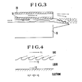
- the effluent passes through the gap between the needle-like electrode 16 and the first tube 19 and is then subjected to contact with the sample sending gas while being sent the tip of the needle-like electrode 16.
- the evaporation of the solvent contained in the effluent is thus accelerated, thereby increasing the concentration of the ions.
- the flow rate v3 of the effluent on the side near the surface of the linear electrode is lower than the flow rate v2 on the side of the liquid surface. This is because of the presence of friction between the effluent and the surface of the needle-like electrode 16.
- v2 is the flow rate of the sample sending gas.
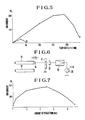
- Fig. 5 is a drawing which shows a relationship between the amount of the effluent, which flows into the ion extractor 6′, and the value of an ion current.
- the conditions for obtaining the data shown in the drawing are as follows:
- the diameter of the needle-like electrode 16 was 100 ⁇ m (0.1 mm), with the tip thereof being pointed by electrolytic polishing so that the radius thereof was several ⁇ m. Dry nitrogen gas was used as the sample sending gas, and the flow rate was set to 1 l /min. As shown in Fig. 2C, the length of projection at the tip of the needle-like electrode 16 was 5 mm, the external diameter and the internal diameter of the first tube 19 were 1 mm and 0.25 mm, respectively, and the external diameter and the internal diameter of the second tube 20 were 4 mm and 2 mm, respectively.
- the voltage applied to the needle-like electrode 16 was +3 KV.
- a curve A represents the data obtained when the needle-like electrode 16 was present
- a curve B represents the data obtained when the needle-like electrode 16 was not present. It is found from these data that ionization is stably and effectively performed owing to the presence of the needle-like electrode 16 even if the flow rate is relatively high. On the other hand, when the needle-like electrode 16 is not present, the maximum flow rate is several tens m l . It is therefore found that the presence of the needle-like electrode 16 enables the achievement of stable and effective ionization even if the flow rate of the effluent is relatively high.
- Fig. 6 shows a system for measuring ion currents which was used for obtaining the data shown in Fig. 5.
- character A denotes a case using the needle-like electrode
- character B denotes a case using no needle-like electrode.
- Reference numeral 8′ denotes an extraction electrode; reference numeral 12′, an ion detector; reference numeral 13′, an amplifier; and reference numeral 30, an ammeter.
- Fig. 7 shows a relationship of the value of ion current to the amount (length) of projection of the needle-like electrode 16 from the first tube 19.
- the data shown in the drawing was obtained by using the system shown in Fig. 6. It is found from the data that there is substantially no effect when the amount of projection is zero or extremely large.
- the tip of the needle-like electrode 16 may be sharp, flat as shown in Figs. 8A, 8B, 10A and 10B, or round as shown in Figs. 9A and 9B.
- the sectional forms of the needle-like electrode 16 and the first and second tubes 19 and 20 may be circular as shown in Figs. 8A, 8B, 9A, 9B or rectangular as shown in Figs. 10A, 10B.
- Figs. 11 and 12 respectively show methods of heating.
- Fig. 11 shows a method in which the whole of the nozzle potion 6 is surrounded by a heat block 21 which is heated by using cartridge heaters 23.
- Fig. 12 shows a method in which nebulized components are passed through a hollow heat block 24 containing cartridge heaters 23 so as to be evaporated.
- reference numeral 22 denotes a thermocouple for measuring temperatures.
Landscapes
- Chemical & Material Sciences (AREA)
- Analytical Chemistry (AREA)
- Dispersion Chemistry (AREA)
- Physics & Mathematics (AREA)
- Biochemistry (AREA)
- Life Sciences & Earth Sciences (AREA)
- Health & Medical Sciences (AREA)
- General Health & Medical Sciences (AREA)
- General Physics & Mathematics (AREA)
- Immunology (AREA)
- Pathology (AREA)
- Engineering & Computer Science (AREA)
- Plasma & Fusion (AREA)
- Other Investigation Or Analysis Of Materials By Electrical Means (AREA)
- Electron Tubes For Measurement (AREA)
Applications Claiming Priority (2)
| Application Number | Priority Date | Filing Date | Title |
|---|---|---|---|
| JP63249860A JPH0713624B2 (ja) | 1988-10-05 | 1988-10-05 | イオンの抽出および分析装置 |
| JP249860/88 | 1988-10-05 |
Publications (3)
| Publication Number | Publication Date |
|---|---|
| EP0362813A2 true EP0362813A2 (fr) | 1990-04-11 |
| EP0362813A3 EP0362813A3 (fr) | 1991-03-20 |
| EP0362813B1 EP0362813B1 (fr) | 1994-09-21 |
Family
ID=17199268
Family Applications (1)
| Application Number | Title | Priority Date | Filing Date |
|---|---|---|---|
| EP89118390A Expired - Lifetime EP0362813B1 (fr) | 1988-10-05 | 1989-10-04 | Analyseur d'ions |
Country Status (4)
| Country | Link |
|---|---|
| US (1) | US5132002A (fr) |
| EP (1) | EP0362813B1 (fr) |
| JP (1) | JPH0713624B2 (fr) |
| DE (1) | DE68918384D1 (fr) |
Cited By (4)
| Publication number | Priority date | Publication date | Assignee | Title |
|---|---|---|---|---|
| EP0452930A2 (fr) * | 1990-04-18 | 1991-10-23 | Hitachi, Ltd. | Dispositif pour l'ionisation et la spectrométrie de masse d'un échantillon |
| EP0482454A2 (fr) * | 1990-10-26 | 1992-04-29 | Hitachi, Ltd. | Spectromètre de masse et dispositif d'introduction d'échantillon utilisant un pulvérisateur ionique |
| DE4410726A1 (de) * | 1993-03-31 | 1994-10-06 | Hewlett Packard Co | Teilchenstrahlgenerator für eine LC/MS-Schnittstelle |
| EP0860858A1 (fr) * | 1997-02-20 | 1998-08-26 | Shimadzu Corporation | Ioniseur à électrospray |
Families Citing this family (5)
| Publication number | Priority date | Publication date | Assignee | Title |
|---|---|---|---|---|
| US5792347A (en) * | 1997-04-10 | 1998-08-11 | Metafix Inc. | Effluent precipitation and neutralization vessel and method |
| JP4882559B2 (ja) * | 2006-07-11 | 2012-02-22 | 株式会社島津製作所 | 液体クロマトグラフ質量分析計 |
| DE102007059726B4 (de) | 2007-12-12 | 2010-01-07 | Excor Korrosionsforschung Gmbh | Dampfphasen-Korrosionsinhibitoren, Verfahren zu deren Herstellung und deren Verwendung |
| US7917966B2 (en) * | 2008-08-21 | 2011-03-29 | Snu R&Db Foundation | Aligned nanostructures on a tip |
| US8070929B2 (en) * | 2008-08-21 | 2011-12-06 | Snu R&Db Foundation | Catalyst particles on a tip |
Citations (2)
| Publication number | Priority date | Publication date | Assignee | Title |
|---|---|---|---|---|
| US4209696A (en) * | 1977-09-21 | 1980-06-24 | Fite Wade L | Methods and apparatus for mass spectrometric analysis of constituents in liquids |
| US4298795A (en) * | 1978-09-08 | 1981-11-03 | Japan Spectroscopic Co. Ltd | Method and apparatus for introducing samples to a mass spectrometer |
Family Cites Families (3)
| Publication number | Priority date | Publication date | Assignee | Title |
|---|---|---|---|---|
| GB1483966A (en) * | 1974-10-23 | 1977-08-24 | Sharp Kk | Vapourized-metal cluster ion source and ionized-cluster beam deposition |
| JPS58156848A (ja) * | 1982-03-15 | 1983-09-17 | Fuji Photo Film Co Ltd | イオン選択電極及びその製造法 |
| JPS5932861A (ja) * | 1982-08-18 | 1984-02-22 | Jeol Ltd | 液体クロマトグラフ質量分析装置 |
-
1988
- 1988-10-05 JP JP63249860A patent/JPH0713624B2/ja not_active Expired - Fee Related
-
1989
- 1989-10-03 US US07/416,430 patent/US5132002A/en not_active Expired - Lifetime
- 1989-10-04 EP EP89118390A patent/EP0362813B1/fr not_active Expired - Lifetime
- 1989-10-04 DE DE68918384T patent/DE68918384D1/de not_active Expired - Lifetime
Patent Citations (2)
| Publication number | Priority date | Publication date | Assignee | Title |
|---|---|---|---|---|
| US4209696A (en) * | 1977-09-21 | 1980-06-24 | Fite Wade L | Methods and apparatus for mass spectrometric analysis of constituents in liquids |
| US4298795A (en) * | 1978-09-08 | 1981-11-03 | Japan Spectroscopic Co. Ltd | Method and apparatus for introducing samples to a mass spectrometer |
Non-Patent Citations (2)
| Title |
|---|
| ANAL. CHEM., vol. 59, no. 22, 15th November 1987, pages 2642-2646; A.P. BRUINS et al.: "Ion spray interface for combined liquid chromatography/atmospheric pressure ionization mass spectrometry" * |
| JOURNAL OF PHYSICS AND CHEMISTRY, vol. 88, 1984, pages 4451-4459; M. YAMASHITA et al.: "Electrospray ion source, another variation on the free-jet theme" * |
Cited By (8)
| Publication number | Priority date | Publication date | Assignee | Title |
|---|---|---|---|---|
| EP0452930A2 (fr) * | 1990-04-18 | 1991-10-23 | Hitachi, Ltd. | Dispositif pour l'ionisation et la spectrométrie de masse d'un échantillon |
| EP0452930A3 (en) * | 1990-04-18 | 1991-12-18 | Hitachi, Ltd. | Apparatus for sample ionization and mass spectrometry |
| US5170052A (en) * | 1990-04-18 | 1992-12-08 | Hitachi, Ltd. | Apparatus for sample ionization and mass spectrometry |
| EP0482454A2 (fr) * | 1990-10-26 | 1992-04-29 | Hitachi, Ltd. | Spectromètre de masse et dispositif d'introduction d'échantillon utilisant un pulvérisateur ionique |
| EP0482454A3 (en) * | 1990-10-26 | 1992-08-12 | Hitachi, Ltd. | Mass spectrometer and sample introduction device using a ion sprayer |
| DE4410726A1 (de) * | 1993-03-31 | 1994-10-06 | Hewlett Packard Co | Teilchenstrahlgenerator für eine LC/MS-Schnittstelle |
| EP0860858A1 (fr) * | 1997-02-20 | 1998-08-26 | Shimadzu Corporation | Ioniseur à électrospray |
| US6043487A (en) * | 1997-02-20 | 2000-03-28 | Shimadzu Corporation | Electrospray ionizer |
Also Published As
| Publication number | Publication date |
|---|---|
| EP0362813B1 (fr) | 1994-09-21 |
| JPH0298662A (ja) | 1990-04-11 |
| JPH0713624B2 (ja) | 1995-02-15 |
| DE68918384D1 (de) | 1994-10-27 |
| EP0362813A3 (fr) | 1991-03-20 |
| US5132002A (en) | 1992-07-21 |
Similar Documents
| Publication | Publication Date | Title |
|---|---|---|
| JP3353561B2 (ja) | 溶液の質量分析に関する方法と装置 | |
| US4935624A (en) | Thermal-assisted electrospray interface (TAESI) for LC/MS | |
| US4999493A (en) | Electrospray ionization interface and method for mass spectrometry | |
| US5436446A (en) | Analyzing time modulated electrospray | |
| US5873523A (en) | Electrospray employing corona-assisted cone-jet mode | |
| US6407382B1 (en) | Discharge ionization source | |
| JP4657451B2 (ja) | 電気スプレー質量分析のための渦状ガス流インターフェース | |
| US20030202920A1 (en) | Process and apparatus for adjusting an aerosol charge by using a corona discharge | |
| JPH0854370A (ja) | キャピラリー電気泳動・質量分析計 | |
| US7041966B2 (en) | Apparatus for delivering ions from a grounded electrospray assembly to a vacuum chamber | |
| JPH042033A (ja) | 試料のイオン化および質量分析のための装置 | |
| EP0362813B1 (fr) | Analyseur d'ions | |
| JPH04163849A (ja) | 質量分析計 | |
| JP4254546B2 (ja) | 質量分析装置 | |
| JP2596343B2 (ja) | 質量分析方法 | |
| JPH06310088A (ja) | 質量分析装置イオン源 | |
| JPS60237354A (ja) | 熱スプレ−イオン源とその効率を改善する方法 | |
| JPH06102246A (ja) | 質量分析計 | |
| JP2872746B2 (ja) | エレクトロスプレー式質量分析装置 | |
| JP3353752B2 (ja) | イオン源 | |
| JP2002190272A (ja) | エレクトロスプレー・イオン源 | |
| JP2777614B2 (ja) | 質量分析方法および質量分析計 | |
| JPH11108895A (ja) | 液体クロマトグラフ質量分析装置 | |
| JPH1164289A (ja) | 液体クロマトグラフ質量分析装置 | |
| JP2003130848A (ja) | 溶液の質量分析に関する方法と装置 |
Legal Events
| Date | Code | Title | Description |
|---|---|---|---|
| PUAI | Public reference made under article 153(3) epc to a published international application that has entered the european phase |
Free format text: ORIGINAL CODE: 0009012 |
|
| AK | Designated contracting states |
Kind code of ref document: A2 Designated state(s): DE GB |
|
| PUAL | Search report despatched |
Free format text: ORIGINAL CODE: 0009013 |
|
| 17P | Request for examination filed |
Effective date: 19901220 |
|
| AK | Designated contracting states |
Kind code of ref document: A3 Designated state(s): DE GB |
|
| 17Q | First examination report despatched |
Effective date: 19930624 |
|
| GRAA | (expected) grant |
Free format text: ORIGINAL CODE: 0009210 |
|
| AK | Designated contracting states |
Kind code of ref document: B1 Designated state(s): DE GB |
|
| REF | Corresponds to: |
Ref document number: 68918384 Country of ref document: DE Date of ref document: 19941027 |
|
| PG25 | Lapsed in a contracting state [announced via postgrant information from national office to epo] |
Ref country code: DE Effective date: 19941222 |
|
| PLBE | No opposition filed within time limit |
Free format text: ORIGINAL CODE: 0009261 |
|
| STAA | Information on the status of an ep patent application or granted ep patent |
Free format text: STATUS: NO OPPOSITION FILED WITHIN TIME LIMIT |
|
| 26N | No opposition filed | ||
| REG | Reference to a national code |
Ref country code: GB Ref legal event code: IF02 |
|
| PGFP | Annual fee paid to national office [announced via postgrant information from national office to epo] |
Ref country code: GB Payment date: 20060925 Year of fee payment: 18 |
|
| GBPC | Gb: european patent ceased through non-payment of renewal fee |
Effective date: 20071004 |
|
| PG25 | Lapsed in a contracting state [announced via postgrant information from national office to epo] |
Ref country code: GB Free format text: LAPSE BECAUSE OF NON-PAYMENT OF DUE FEES Effective date: 20071004 |