EP0361406B1 - Machine à mouler par injection - Google Patents
Machine à mouler par injection Download PDFInfo
- Publication number
- EP0361406B1 EP0361406B1 EP89117783A EP89117783A EP0361406B1 EP 0361406 B1 EP0361406 B1 EP 0361406B1 EP 89117783 A EP89117783 A EP 89117783A EP 89117783 A EP89117783 A EP 89117783A EP 0361406 B1 EP0361406 B1 EP 0361406B1
- Authority
- EP
- European Patent Office
- Prior art keywords
- mold
- gate
- piston
- ejecting
- cutting
- Prior art date
- Legal status (The legal status is an assumption and is not a legal conclusion. Google has not performed a legal analysis and makes no representation as to the accuracy of the status listed.)
- Expired - Lifetime
Links
Images

Classifications
-
- B—PERFORMING OPERATIONS; TRANSPORTING
- B29—WORKING OF PLASTICS; WORKING OF SUBSTANCES IN A PLASTIC STATE IN GENERAL
- B29C—SHAPING OR JOINING OF PLASTICS; SHAPING OF MATERIAL IN A PLASTIC STATE, NOT OTHERWISE PROVIDED FOR; AFTER-TREATMENT OF THE SHAPED PRODUCTS, e.g. REPAIRING
- B29C45/00—Injection moulding, i.e. forcing the required volume of moulding material through a nozzle into a closed mould; Apparatus therefor
- B29C45/17—Component parts, details or accessories; Auxiliary operations
- B29C45/38—Cutting-off equipment for sprues or ingates
-
- B—PERFORMING OPERATIONS; TRANSPORTING
- B29—WORKING OF PLASTICS; WORKING OF SUBSTANCES IN A PLASTIC STATE IN GENERAL
- B29C—SHAPING OR JOINING OF PLASTICS; SHAPING OF MATERIAL IN A PLASTIC STATE, NOT OTHERWISE PROVIDED FOR; AFTER-TREATMENT OF THE SHAPED PRODUCTS, e.g. REPAIRING
- B29C45/00—Injection moulding, i.e. forcing the required volume of moulding material through a nozzle into a closed mould; Apparatus therefor
- B29C45/17—Component parts, details or accessories; Auxiliary operations
- B29C45/40—Removing or ejecting moulded articles
- B29C45/4005—Ejector constructions; Ejector operating mechanisms
-
- B—PERFORMING OPERATIONS; TRANSPORTING
- B29—WORKING OF PLASTICS; WORKING OF SUBSTANCES IN A PLASTIC STATE IN GENERAL
- B29D—PRODUCING PARTICULAR ARTICLES FROM PLASTICS OR FROM SUBSTANCES IN A PLASTIC STATE
- B29D11/00—Producing optical elements, e.g. lenses or prisms
-
- B—PERFORMING OPERATIONS; TRANSPORTING
- B29—WORKING OF PLASTICS; WORKING OF SUBSTANCES IN A PLASTIC STATE IN GENERAL
- B29L—INDEXING SCHEME ASSOCIATED WITH SUBCLASS B29C, RELATING TO PARTICULAR ARTICLES
- B29L2017/00—Carriers for sound or information
- B29L2017/001—Carriers of records containing fine grooves or impressions, e.g. disc records for needle playback, cylinder records
- B29L2017/003—Records or discs
- B29L2017/005—CD''s, DVD''s
Definitions
- the present invention relates to an injection molding machine and, more particularly, to an injection molding machine including a mold for molding disk-shaped recording medium carriers such as optical disk substrates (hereinafter abbreviated to "optical disk substrates").
- a conventional mold for molding optical disk substrates includes an ejector rod for ejecting a molded substrate, a gate-cutting punch, and an ejector pin for ejecting a sprue.
- the substrate-ejecting ejector rod is movably fitted in the main body of the mold while facing the cavity.
- the gate-cutting punch and the sprue-ejecting ejector pin are movably fitted within the ejector rod while concentrically engaging with each other in such a manner as to be movable relative to each other.
- the conventional mold also incorporates therein a pneumatic cylinder to actuate mechanisms for ejecting the substrate and a hydraulic cylinder to actuate a gate-cutting mechanism.
- the present invention has been made in order to overcome the above-stated problems. It is an object of the present invention to provide an injection molding machine from which those drawbacks resulting from the incorporation of a hydraulic cylinder in the mold are eliminated by mounting both a gate-cutting cylinder and a cylinder for ejecting a substrate and a sprue in a movable mold-mounting plate on the side that is not the side on which the mold is mounted.
- an injection molding machine comprising: a mold-mounting plate having a front surface allowing a mold to be mounted thereon; a gate-cutting punch slidably inserted in a hole extending through the mold-mounting plate and opening in the front and rear surfaces of the plate, the gate-cutting punch having in the center thereof a bore extending longitudinally; an ejector pin slidably inserted in the bore of the gate-cutting punch; a gate-cutting drive cylinder mounted on the rear surface of the mold-mounting plate and having a piston capable of abutting against a rear end of the gate-cutting punch, the piston being formed with a stepped bore having a large-diameter front portion and a small-diameter rear portion which are aligned on the same axial line; an ejector rod extending through the stepped bore of the piston, and having a large-diameter portion slidable within the large-diameter portion of the
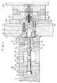
- reference numeral 1 denotes a movable mold-mounting plate disposed in opposition to a fixed mold-mounting plate 104 in such a manner as to be movable toward and away from the fixed mold-mounting plate when moved by a mold-clamping device (i.e., a mold-clamping cylinder, in this embodiment).
- a mold-clamping device i.e., a mold-clamping cylinder, in this embodiment.
- a movable part of the mold is mounted on the movable mold-mounting plate 1.
- an ejector rod 3 for ejecting a molded substrate is movably fitted in the main body 103,101 of the mold while facing the cavity.
- a gate-cutting punch 4 and a sprue-ejecting ejector pin 5 are movably fitted through a longitudinal bore formed in the center of the substrate-ejecting ejector rod 3 while concentrically engaging with each other in such a manner as to be movable relative to each other.
- Return springs 119, 126 and 130 urge the substrate-ejecting ejector rod 3, the gate-cutting punch 4, and the sprue-ejecting ejector pin 5 with forces capable of returning these members to their most retracted positions.
- the arrangement of the substrate-ejecting ejector rod 3 is such that, after the sprue-ejecting ejector pin 5 has advanced toward the cavity by a certain distance (a distance greater than the gate-cutting distance), a projection 128 (See Fig. 3) of the ejector pin 5 comes into contact with the substrate-ejecting ejector rod 3 so that the substrate-ejecting ejector rod 3 advances in synchronization with the advancement of the ejector pin 5.
- Fig. 1 shows the state where the movable part 103,101 of the mold is mounted on the movable mold-mounting plate 1, and, simultaneously, the substrate-ejecting ejector rod 3, the gate-cutting punch 4, and the sprue-ejecting ejector pin 5 are inserted in a hole extending through the movable mold-mounting plate 1 while all of these members 3 to 5 are retracted to the side remote from the side on which the mold is mounted.
- a gate-cutting drive cylinder 6 is mounted on the rear side of the movable mold-mounting plate 1 which is not the side on which the mold is mounted.
- the drive cylinder 6 has a piston 8 movably received in a cylinder block 7, with oil chambers 9 and 10 defined behind and ahead of the piston 8, respectively.
- the piston 8 has, on its side close to the movable mold-mounting plate 1, a ring-shaped abutting portion 11 capable of abutting against the gate-cutting punch 4 inserted through the movable mold-mounting plate 1 and associated with the mold.
- a bore 12 is formed in the center of the piston 8 in such a manner as to face the inside of the ring-shaped abutting portion 11, and has a diameter smaller than the bore defined inside the portion 11.
- An ejector rod 13 is movably inserted in the piston 8.
- the ejector rod 13 is, at its front end, capable of abutting against the sprue-ejecting ejector pin 5 inserted through the movable mold-mounting plate 1 and associated with the mold.
- the ejector rod 13 has, at its intermediate position, a large-diameter portion 14. The side of this large-diameter portion 14 which is remote from the sprue-ejecting ejector pin 5 is engageable with the piston 8 so as to allow engagement between the ejector rod 13 and the piston 8.
- the ejector rod 13 extends rearwardly through the cylinder block 7 and into a spacer block 15.
- a stroke-adjusting stopper 16 allowing the stroke of the longitudinal movement of the ejector rod 13 to be adjusted is fixed to a rear end portion of the rod 13 by means of a lock nut 17.
- a sprue-ejecting drive cylinder 18 is provided concentrically with the gate-cutting drive cylinder 6 on that side of the drive-cylinder 6 which is remote from the mold, with the spacer block 15 disposed between the drive cylinders 6 and 18.
- the drive cylinder 18 has a piston 20 movably received in a cylinder block 19, with oil chambers 21 and 22 defined behind and ahead of the piston 20.
- a piston rod 23 of the piston 20 extends frontwardly through the cylinder block 19 and into the spacer block 15.
- the piston rod 23 is connected to the ejector rod 13 by means of a link nut 24, and this connection is locked by a lock nut 25.
- the spacer block 15 has a hollowed out structure in which the block 15 is open on one side thereof, so that the ejector rod 13 and the piston rod 23 can be connected to each other, and the position of the stroke-adjusting stopper 16 can be adjusted, utilizing the opening.
- the clamping device (the ram of the clamping cylinder alone is shown in the drawing) is connected to the movable mold-mounting plate 1 via the above-described gate-cutting drive cylinder 6, the spacer block 15, and the sprue-ejecting drive cylinder 18.
- an ejecting operation is performed first by the gate-cutting cylinder 6. Specifically, when pressure oil is supplied to the rear oil chamber 9 while the front oil chamber 10 communicates with an associated tank (not shown), the piston 8 advances toward the movable mold-mounting plate 1. This advancement causes the ring-shaped abutting portion 11 of the piston 8 to abut against the gate-cutting punch 4 and to push the punch 4 against the force of the return spring 126. As a result, the gate-cutting punch 4 advances within the substrate-ejecting ejector rod 3 until it projects by a distance approximately corresponding to the thickness of a substrate, thereby performing a gate-cutting action.
- the ejector rod 13 has its surface on the side remote from the sprue-ejecting ejector pin 5 kept in contact with the piston 8. Therefore, during the gate-cutting action, the ejector rod 13 moves together with the piston 8 toward the movable mold-mounting plate 1. In this way, the mutual relationship in position between the ejector rod 13 and the piston 8 is maintained.
- the movable mold-mounting plate 1 is retracted to open the mold.
- an ejecting operation is performed by the sprue-ejecting drive cylinder 18.
- the piston 20 and the piston rod 23 advance toward the movable mold-mounting plate 1.
- the piston rod 23 is connected to the ejector rod 13 via the link nut 24 and the lock nut 25. Therefore, the ejector rod 13 also advances a certain distance from its position resulting from its movement together with the piston 8 until the stroke-adjusting stopper 16 abuts against the cylinder block 7a.
- the ejector rod 13 advances, it pushes the sprue-ejecting ejector pin 5 against the force of the return spring 130. As a result, a sprue-ejecting action is performed.
- the projections 128 provided on the rear end portion of the sprue-ejecting ejector pin 5 are projected outwardly through grooves 121 of the gate-cutting punch 4 (See Fig. 2) and axially move along the grooves 4 so as to be capable of abutting against the rear end of the substrate-ejecting ejector rod 3.
- the projections 128 abut against the rear end of the substrate-ejecting ejector rod 3 so that the substrate-ejecting rod 3 advances in synchronization with the sprue-ejecting ejector pin 5.
- the substrate-ejecting ejector rod 3 advances, it is brought into abutment with the inner peripheral portion of the substrate and pushes the substrate against the force of the return spring 126, thereby performing a substrate-ejecting action substantially in synchronization with the sprue-ejecting action.
- Changeover valves in the control circuits for the sprue-ejecting drive cylinder 18 and the gate-cutting drive cylinder 6 are operated in such a manner that pressure oil is supplied to the front oil chamber 22 while the rear oil chamber 21 communicates with the tank, thereby retracting the spruce-ejecting drive cylinder 18. Thereafter, pressure oil is supplied to the front oil chamber 10 while the rear oil chamber 9 communicates with the tank, thereby retracting the gate-cutting drive cylinder 6.
- the operation of replacing the mold is performed by dismounting the movable mold part mounted on the movable mold-mounting plate 1 and then mounting a new movable mold part.
- the gate-cutting drive cylinder 6 and the sprue-ejecting drive cylinder 18 do not require the operation of connecting them through pipe lines.
- the injection molding machine is described as used to mold disk substrates.
- this is a mere example, and it would be easily understood that the present invention is also applicable to molding machines exclusively for use in the molding of various other molded products so far as the molding of the product involves a single action.
- both the gate-cutting drive cylinder and the sprue-ejecting drive cylinder are mounted on the mold-mounting plate and are not provided on the same side as the mold.
- This arrangement is advantageous in that the work of the injection molding machine can be clearly divided between two parts of the machine, the part including the mold taking over the achievement of precise dimensions, another part of the machine taking over the drive mechanisms.
- This allotment of work enables the mold to be manufactured without need for considerations to be given to such mechanisms as the mechanism for sealing, e.g., high-pressure hydraulic fluid, and the mechanism for assuring pressure resistance. Accordingly, the mold can be designed and manufactured with ease, while also facilitating the addition of mechanisms for adjusting the gate-cutting distance and the ejecting distance.
- the structure of the mold is rendered simple because such mechanism as the high-pressure hydraulic fluid sealing mechanism, and the pressure-resistance assuring mechanism are eliminated, and the number of the required component parts is reduced. Accordingly, the size and the weight of the mold can be reduced by a great extent.
Landscapes
- Engineering & Computer Science (AREA)
- Manufacturing & Machinery (AREA)
- Mechanical Engineering (AREA)
- Health & Medical Sciences (AREA)
- Ophthalmology & Optometry (AREA)
- Moulds For Moulding Plastics Or The Like (AREA)
- Injection Moulding Of Plastics Or The Like (AREA)
Claims (1)
- Machine de moulage par injection comprenant :
une plaque (1) de montage de moule ayant une surface avant permettant à un moule d'être monté sur celle-ci,
un poinçon (4) de découpe d'ouverture inséré de manière coulissante dans un alésage s'étendant à travers ladite plaque de montage de moule (1) et débouchant dans les surfaces avant et arrière de ladite plaque, ledit poinçon (4) de découpe d'ouverture ayant au niveau de son axe un alésage s'étendant longitudinalement,
un doigt éjecteur (5) inséré de manière coulissante dans ledit alésage dudit poinçon (4) de découpe d'ouverture,
un vérin (6) d'entraînement de découpe d'ouverture monté sur la surface arrière de ladite plaque (1) de montage de moule et ayant un piston (8) capable de venir en butée contre une extrémité arrière dudit poinçon (4) de découpe d'ouverture, ledit piston (8) comportant un alésage étagé (12) ayant une partie avant de grand diamètre et une partie arrière de petit diamètre qui sont alignées sur la même ligne axiale,
une tige éjectrice (13) s'étendant à travers ledit alésage étagé (12) dudit piston (8), et ayant une partie (14) de grand diamètre pouvant coulisser dans ladite partie de grand diamètre dudit alésage étagé (12), une extrémité avant de ladite tige éjectrice (13) étant susceptible de venir en butée contre une extrémité arrière dudit doigt éjecteur (5), et
un vérin (18) d'entraînement d'éjection de carotte prévu derrière ledit vérin (6) d'entraînement de découpe d'ouverture sur la même ligne axiale, ledit vérin (18) d'entraînement d'éjection de carotte ayant une tige de piston (20) reliée à l'extrémité arrière de ladite tige éjectrice (13).
Priority Applications (1)
| Application Number | Priority Date | Filing Date | Title |
|---|---|---|---|
| AT89117783T ATE89215T1 (de) | 1988-09-30 | 1989-09-26 | Spritzgiessmaschine. |
Applications Claiming Priority (2)
| Application Number | Priority Date | Filing Date | Title |
|---|---|---|---|
| JP63246792A JP2683059B2 (ja) | 1988-09-30 | 1988-09-30 | 射出成形機 |
| JP246792/88 | 1988-09-30 |
Publications (3)
| Publication Number | Publication Date |
|---|---|
| EP0361406A2 EP0361406A2 (fr) | 1990-04-04 |
| EP0361406A3 EP0361406A3 (fr) | 1991-05-29 |
| EP0361406B1 true EP0361406B1 (fr) | 1993-05-12 |
Family
ID=17153741
Family Applications (1)
| Application Number | Title | Priority Date | Filing Date |
|---|---|---|---|
| EP89117783A Expired - Lifetime EP0361406B1 (fr) | 1988-09-30 | 1989-09-26 | Machine à mouler par injection |
Country Status (6)
| Country | Link |
|---|---|
| EP (1) | EP0361406B1 (fr) |
| JP (1) | JP2683059B2 (fr) |
| KR (1) | KR0143236B1 (fr) |
| AT (1) | ATE89215T1 (fr) |
| CA (1) | CA1327261C (fr) |
| DE (1) | DE68906495T2 (fr) |
Families Citing this family (8)
| Publication number | Priority date | Publication date | Assignee | Title |
|---|---|---|---|---|
| JPH056101Y2 (fr) * | 1988-10-28 | 1993-02-17 | ||
| EP0580258B1 (fr) * | 1992-07-20 | 1997-01-29 | Koninklijke Philips Electronics N.V. | Dispositif de moulage par injection et moule convenant pour être utilisé dans ce dispositif |
| KR100355741B1 (ko) * | 1999-09-06 | 2002-10-19 | 스미도모쥬기가이고교 가부시키가이샤 | 디스크성형장치의 게이트컷장치 및 게이트컷방법 |
| JP3406561B2 (ja) | 2000-03-21 | 2003-05-12 | 住友重機械工業株式会社 | 射出成形機の製品突出し装置 |
| US20130025559A1 (en) * | 2011-06-10 | 2013-01-31 | Honda Motor Co., Ltd. | High pressure die casting flash containment system |
| CN106671368A (zh) * | 2016-11-25 | 2017-05-17 | 嘉兴信元精密模具科技有限公司 | 一种注塑模的水口和水口针结构 |
| CN106393590B (zh) * | 2016-11-25 | 2019-05-03 | 厦门精卫模具有限公司 | 一种能自动切除料头并形成通孔的注塑模具 |
| CN108568952B (zh) * | 2017-06-29 | 2024-04-19 | 常州星宇车灯股份有限公司 | 一种反射镜灯泡孔处环形进胶模内自动去除浇口的模具 |
Family Cites Families (4)
| Publication number | Priority date | Publication date | Assignee | Title |
|---|---|---|---|---|
| US2613395A (en) * | 1949-02-24 | 1952-10-14 | M & W Company Inc | Apparatus and method for producing disk phonograph records |
| US3989436A (en) * | 1975-12-18 | 1976-11-02 | Rca Corporation | Apparatus for producing injection molded and centrally apertured disc records |
| US4185955A (en) * | 1977-10-31 | 1980-01-29 | Mca Disco-Vision, Inc. | Apparatus for replicating centrally apertured video disc records |
| ATE71575T1 (de) * | 1986-02-26 | 1992-02-15 | Meiki Seisakusho Kk | Formvorrichtung und verfahren zum herstellen von platten mit mittelloch. |
-
1988
- 1988-09-30 JP JP63246792A patent/JP2683059B2/ja not_active Expired - Lifetime
-
1989
- 1989-09-25 CA CA000612770A patent/CA1327261C/fr not_active Expired - Fee Related
- 1989-09-26 DE DE8989117783T patent/DE68906495T2/de not_active Expired - Lifetime
- 1989-09-26 EP EP89117783A patent/EP0361406B1/fr not_active Expired - Lifetime
- 1989-09-26 AT AT89117783T patent/ATE89215T1/de not_active IP Right Cessation
- 1989-09-30 KR KR1019890014141A patent/KR0143236B1/ko not_active IP Right Cessation
Also Published As
| Publication number | Publication date |
|---|---|
| DE68906495D1 (de) | 1993-06-17 |
| CA1327261C (fr) | 1994-03-01 |
| EP0361406A3 (fr) | 1991-05-29 |
| KR0143236B1 (ko) | 1998-07-15 |
| DE68906495T2 (de) | 1993-09-09 |
| ATE89215T1 (de) | 1993-05-15 |
| EP0361406A2 (fr) | 1990-04-04 |
| KR900004479A (ko) | 1990-04-12 |
| JPH0292610A (ja) | 1990-04-03 |
| JP2683059B2 (ja) | 1997-11-26 |
Similar Documents
| Publication | Publication Date | Title |
|---|---|---|
| EP0342235B1 (fr) | Mecanisme de serrage pour machines de moulage par injection | |
| US5865241A (en) | Die casting machine with precisely positionable obliquely moving die core pieces | |
| EP0361406B1 (fr) | Machine à mouler par injection | |
| GB1166081A (en) | Improvements in or relating to Injection Moulding Machines | |
| EP1556181B1 (fr) | Procede et appareil permettant de couler sous pression un bloc en v pour un moteur a combustion interne | |
| US5253997A (en) | Injection molding machine for molding disk-shaped recording medium carriers | |
| EP1312457B1 (fr) | Procédé et dispositif de manipulation robotique de paraisons | |
| EP1683621B1 (fr) | Dispositif de serrage de moules et procede de moulage | |
| JP3152601B2 (ja) | ディスク射出成形金型の固定側と可動側の円盤キャビティプレートの整列案内装置 | |
| JP2870630B2 (ja) | 成形装置 | |
| US3916766A (en) | Control valve means for hydraulic press | |
| JP2622411B2 (ja) | 光ディスク基板成形用金型 | |
| JPH11254493A (ja) | ディスク成形装置のゲートカット装置及びゲートカット方法 | |
| CA1335623C (fr) | Machine de coulee | |
| US5223273A (en) | Bladder control mechanism of tire vulcanizer | |
| JP2732774B2 (ja) | 型締シリンダのピストン後退量設定装置 | |
| JPH088034Y2 (ja) | 位置決め治具 | |
| JPS60247530A (ja) | 金型のスプルブツシユ構造 | |
| JPH01107953A (ja) | 射出成形機 | |
| JP2915760B2 (ja) | 局部加圧式の射出成形機 | |
| US3642407A (en) | Moving mechanism for injection molding machines or the like | |
| KR100355741B1 (ko) | 디스크성형장치의 게이트컷장치 및 게이트컷방법 | |
| JPH0292609A (ja) | 光ディスク基板成形用金型 | |
| WO1994013453A1 (fr) | Machine a couler sous pression | |
| JP3245379B2 (ja) | 直圧式型締装置 |
Legal Events
| Date | Code | Title | Description |
|---|---|---|---|
| PUAI | Public reference made under article 153(3) epc to a published international application that has entered the european phase |
Free format text: ORIGINAL CODE: 0009012 |
|
| AK | Designated contracting states |
Kind code of ref document: A2 Designated state(s): AT CH DE FR GB LI NL |
|
| PUAL | Search report despatched |
Free format text: ORIGINAL CODE: 0009013 |
|
| AK | Designated contracting states |
Kind code of ref document: A3 Designated state(s): AT CH DE FR GB LI NL |
|
| 17P | Request for examination filed |
Effective date: 19910712 |
|
| 17Q | First examination report despatched |
Effective date: 19920708 |
|
| GRAA | (expected) grant |
Free format text: ORIGINAL CODE: 0009210 |
|
| AK | Designated contracting states |
Kind code of ref document: B1 Designated state(s): AT CH DE FR GB LI NL |
|
| REF | Corresponds to: |
Ref document number: 89215 Country of ref document: AT Date of ref document: 19930515 Kind code of ref document: T |
|
| REF | Corresponds to: |
Ref document number: 68906495 Country of ref document: DE Date of ref document: 19930617 |
|
| ET | Fr: translation filed | ||
| REG | Reference to a national code |
Ref country code: GB Ref legal event code: IF02 |
|
| PGFP | Annual fee paid to national office [announced via postgrant information from national office to epo] |
Ref country code: FR Payment date: 20020910 Year of fee payment: 14 |
|
| PGFP | Annual fee paid to national office [announced via postgrant information from national office to epo] |
Ref country code: AT Payment date: 20020911 Year of fee payment: 14 |
|
| PGFP | Annual fee paid to national office [announced via postgrant information from national office to epo] |
Ref country code: GB Payment date: 20020925 Year of fee payment: 14 |
|
| PGFP | Annual fee paid to national office [announced via postgrant information from national office to epo] |
Ref country code: NL Payment date: 20020930 Year of fee payment: 14 |
|
| PGFP | Annual fee paid to national office [announced via postgrant information from national office to epo] |
Ref country code: DE Payment date: 20021002 Year of fee payment: 14 |
|
| PG25 | Lapsed in a contracting state [announced via postgrant information from national office to epo] |
Ref country code: GB Free format text: LAPSE BECAUSE OF NON-PAYMENT OF DUE FEES Effective date: 20030926 Ref country code: AT Free format text: LAPSE BECAUSE OF NON-PAYMENT OF DUE FEES Effective date: 20030926 |
|
| PGFP | Annual fee paid to national office [announced via postgrant information from national office to epo] |
Ref country code: CH Payment date: 20030930 Year of fee payment: 15 |
|
| PG25 | Lapsed in a contracting state [announced via postgrant information from national office to epo] |
Ref country code: NL Free format text: LAPSE BECAUSE OF NON-PAYMENT OF DUE FEES Effective date: 20040401 Ref country code: DE Free format text: LAPSE BECAUSE OF NON-PAYMENT OF DUE FEES Effective date: 20040401 |
|
| GBPC | Gb: european patent ceased through non-payment of renewal fee |
Effective date: 20030926 |
|
| PG25 | Lapsed in a contracting state [announced via postgrant information from national office to epo] |
Ref country code: FR Free format text: LAPSE BECAUSE OF NON-PAYMENT OF DUE FEES Effective date: 20040528 |
|
| NLV4 | Nl: lapsed or anulled due to non-payment of the annual fee |
Effective date: 20040401 |
|
| REG | Reference to a national code |
Ref country code: FR Ref legal event code: ST |
|
| PG25 | Lapsed in a contracting state [announced via postgrant information from national office to epo] |
Ref country code: LI Free format text: LAPSE BECAUSE OF NON-PAYMENT OF DUE FEES Effective date: 20040930 Ref country code: CH Free format text: LAPSE BECAUSE OF NON-PAYMENT OF DUE FEES Effective date: 20040930 |
|
| REG | Reference to a national code |
Ref country code: CH Ref legal event code: PL |
|
| PLBE | No opposition filed within time limit |
Free format text: ORIGINAL CODE: 0009261 |
|
| STAA | Information on the status of an ep patent application or granted ep patent |
Free format text: STATUS: NO OPPOSITION FILED WITHIN TIME LIMIT |