EP0360397B1 - Appareil de mesure d'ophtalmoscope - Google Patents
Appareil de mesure d'ophtalmoscope Download PDFInfo
- Publication number
- EP0360397B1 EP0360397B1 EP89307846A EP89307846A EP0360397B1 EP 0360397 B1 EP0360397 B1 EP 0360397B1 EP 89307846 A EP89307846 A EP 89307846A EP 89307846 A EP89307846 A EP 89307846A EP 0360397 B1 EP0360397 B1 EP 0360397B1
- Authority
- EP
- European Patent Office
- Prior art keywords
- laser beam
- under examination
- eye under
- light
- section
- Prior art date
- Legal status (The legal status is an assumption and is not a legal conclusion. Google has not performed a legal analysis and makes no representation as to the accuracy of the status listed.)
- Expired - Lifetime
Links
Images
Classifications
-
- A—HUMAN NECESSITIES
- A61—MEDICAL OR VETERINARY SCIENCE; HYGIENE
- A61B—DIAGNOSIS; SURGERY; IDENTIFICATION
- A61B3/00—Apparatus for testing the eyes; Instruments for examining the eyes
- A61B3/10—Objective types, i.e. instruments for examining the eyes independent of the patients' perceptions or reactions
- A61B3/14—Arrangements specially adapted for eye photography
- A61B3/15—Arrangements specially adapted for eye photography with means for aligning, spacing or blocking spurious reflection ; with means for relaxing
- A61B3/152—Arrangements specially adapted for eye photography with means for aligning, spacing or blocking spurious reflection ; with means for relaxing for aligning
-
- A—HUMAN NECESSITIES
- A61—MEDICAL OR VETERINARY SCIENCE; HYGIENE
- A61B—DIAGNOSIS; SURGERY; IDENTIFICATION
- A61B3/00—Apparatus for testing the eyes; Instruments for examining the eyes
- A61B3/10—Objective types, i.e. instruments for examining the eyes independent of the patients' perceptions or reactions
- A61B3/117—Objective types, i.e. instruments for examining the eyes independent of the patients' perceptions or reactions for examining the anterior chamber or the anterior chamber angle, e.g. gonioscopes
-
- A—HUMAN NECESSITIES
- A61—MEDICAL OR VETERINARY SCIENCE; HYGIENE
- A61B—DIAGNOSIS; SURGERY; IDENTIFICATION
- A61B3/00—Apparatus for testing the eyes; Instruments for examining the eyes
- A61B3/10—Objective types, i.e. instruments for examining the eyes independent of the patients' perceptions or reactions
- A61B3/12—Objective types, i.e. instruments for examining the eyes independent of the patients' perceptions or reactions for looking at the eye fundus, e.g. ophthalmoscopes
- A61B3/1225—Objective types, i.e. instruments for examining the eyes independent of the patients' perceptions or reactions for looking at the eye fundus, e.g. ophthalmoscopes using coherent radiation
-
- A—HUMAN NECESSITIES
- A61—MEDICAL OR VETERINARY SCIENCE; HYGIENE
- A61B—DIAGNOSIS; SURGERY; IDENTIFICATION
- A61B3/00—Apparatus for testing the eyes; Instruments for examining the eyes
- A61B3/10—Objective types, i.e. instruments for examining the eyes independent of the patients' perceptions or reactions
- A61B3/13—Ophthalmic microscopes
- A61B3/135—Slit-lamp microscopes
Definitions
- This invention relates to an ophthalmological measurement apparatus and more particularly to an ophthalmological measurement apparatus which projects a laser beam into the eye to be examined and outputs a specific measured value based on the state of scattering of the laser beam within the eye.
- Measurement of protein concentration within the anterior chamber of the eye is highly important in determining the presence of inflammation within the eye, namely whether or not a blood-aqueous barrier functions normally.
- the general practice has been to use a slit lamp microscope and to make the determination by visual observation on the basis of grading. While a quantitative method based on photographic measurement has been reported, the fact remains that no easy method for clinical application has yet been developed.
- the intensity of the scattered light is extremely weak.
- the results of the measurement are therefore easily affected by noise components, i.e. by any light present other than the light to be measured. For example, if the measurement is carried out with respect to the anterior chamber and the point of measurement is too close to the crystalline lens, light scattered by the lens will constitute noise and the results of the measurement will vary depending on the location.
- the cornea has a strong lens effect and any light other than that impinging normally thereon is refracted thereby.
- the amount of refraction varies with the point of impingement, with the result that the relationship between the point of measurement (the convergence point of the laser beam) and the point where the light is received (the mask) deviates.
- the depth of the humor aqueous in the anterior chamber is about 3 mm, it is necessary to focus the laser beam at an intermediate portion lying at a depth of between 1 and 2 mm and to receive the light scattered from this measurement point with high accuracy. This requires accurate alignment between the apparatus and the eye under examination, particularly in the horizontal direction, and also makes it necessary to have a method for confirming that the required state of alignment has been achieved.
- the present invention was accomplished in view of these circumstances and its object is to provide an ophthalmological measurement apparatus which enables alignment between the eye under examination and the apparatus to be obtained with ease.
- EP-A-299,709 which is a document under Art.54(3) EPC, there is disclosed an ophthalmological measurement apparatus in which a laser beam is directed into an eye under examination and a measurement value is output on the basis of the state of scattering of the laser beam within the eye under examination.
- the apparatus comprises a laser beam projection section for focusing a laser beam produced by a laser beam source at a predetermined point in the anterior chamber of an eye under examination, a light receiving section provided with a photoelectric conversion element for receiving scattered laser light from the eye under examination, an alignment index projection section for forming at a predetermined point within the eye under examination an alignment index projection section for forming at a predetermined point within the eye under examination an alignment index for use in judging alignment between the apparatus and the eye under examination, an observation section for observing the impingement state of the laser beam and of the light of the alignment index image at the eye under examination, and means for mechanically controlling the relative position between the eye under examination and the apparatus to bring both to proper positional alignment by causing light scattering points produced at the cornea of the eye under examination by the laser beam and the light of the alignment index image to assume predetermined positions within the field of the observation section.
- the present invention concerns an apparatus as set forth in the previous paragraph in which the alignment index projection section and the light receiving section have at least part of their optical paths in common.
- the observation section of the apparatus can be constituted to have indices which indicate the positions which the light scattering points at the eye cornea of the laser beam and the light of the alignment index image should assume within the field of the observation section when the relative positions of the apparatus and the eye under examination are in the predetermined alignment.
- the colours of the laser beam and the light of the alignment index image are preferably made different.
- a slit beam projection section which can be positioned with respect to the eye under examination independently of the laser beam projection section, the light receiving section and the alignment index projection section, whereby the apparatus is also made usable as a slit lamp microscope.
- the light scattering points produced on the cornea of the eye under examination by the laser beam and the light of the alignment index image intrinsically assume the predetermined positions when the apparatus and the eye under examination are in the predetermined alignment.
- the state of alignment between the apparatus and the eye under examination can be evaluated from the position of the light scattering points with ease.
- the judgment regarding alignment is additionally facilitated by providing indices indicating the positions within the field of the observation section that the light scattering points produced by the laser beam and the light of the alignment index image intrinsically assume when alignment is achieved. It is further advantageous, particularly when an arrangement is used in which the laser beam and the light of the alignment index image are of different colors. Moreover, a more compact apparatus can be realized with greater freedom of design by having the alignment index projection section and the light receiving section share at least part of the same optical path.
- the apparatus is also made usable as a slit lamp microscope.
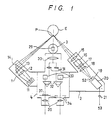
- Figure 1 is a top view of an ophthalmological measurement apparatus in accordance with the present invention.
- the apparatus is constituted mainly of four sections designated by reference numerals 1 to 4.
- Reference numeral 1 denotes a laser beam projection section comprising a semiconductor laser or other such light source (not shown), a mirror 11, a lens 12, a polarizing plate 13, and a mirror 14.
- a laser beam advancing perpendicularly to the surface of the drawing sheet impinges on the mirror 11, advances through the polarizing plate 13, and is reflected by the mirror 14 to converge at convergence point P in the anterior chamber of the eye under examination E.
- the alignment between the eye under examination and the measurement apparatus will be described later.
- Reference numeral 2 denotes a light receiving section which receives light scattered from the vicinity of the convergence point P and comprises a lens 15, a beam splitter 16 for coupling with an alignment index projection optical system to be explained later, an interference filter 17, a lens 18, a shutter S2, a mask 19 and a photomultiplier 20.
- the interference filter 17 is constituted as a narrow-band interference filter whose peak wavelength is the same as the wavelength of the laser beam produced by the laser beam projection section 1.
- the mask 19 is for cutting extraneous light from unrequired regions, and the mask 19 and the convergence point P are positioned conjugately with respect to the optical system of the light receiving section 2.
- Reference numeral 3 denotes a slit beam projection section located forward of an observation section 4 and serves to form a slit image at the convergence point P within the eye under examination E.
- the main elements of the slit beam projection section 3 are disposed perpendicularly to the drawing sheet so that in this figure the only element shown is a prism 29 for reflecting the slit beam in the direction of the eye under examination E.
- the slit beam projection section 3 is constituted so as to be movable independently of the laser beam projection section 1, the light receiving section 2 and the observation section 4, whereby the apparatus can also be used as a slit lamp microscope.
- the observation section 4 has two eyepieces 35, making it possible for the operator to view the measurement region with both eyes and also, as will be explained more completely later, for him to confirm the state of alignment during the alignment operation.
- the observation section 4 comprises lenses 30, 31, prisms 32, 33 and field stops 34.
- an alignment confirmation index plate 37 At the position of the field stop field 34 on the left side as seen in Figure 1, there is provided an alignment confirmation index plate 37. (The alignment confirmation index plate 37 bears two indices and will be described in detail below.)
- the laser beam projection section 1 and the light receiving section 2 are fixed to the observation section 4 such that their optical axes intersect at the eye under examination E at an angle of approximately 90 degrees.
- the laser beam projection section 1, the light receiving section 2 and the slit beam projection section 3 will now be explained in detail with reference to Figures 2 to 4.
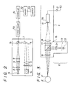
- the structure of the laser beam projection section 1 is shown in Figure 2.
- the laser beam from a semiconductor laser 5 serving as a light source is converted into a parallel beam by a collimator 6 and then is formed into a circular parallel beam by an elliptical beam expander constituted of lenses 7 and 8. It then proceeds through a relay lens 9 and a movable mirror 10 to the mirror 11.
- the movable mirror 10 is driven by a motor or the like for angular adjustment.
- the angular position of the movable mirror 10 is controlled by a controller 51 through a mirror drive circuit 50, whereby the laser beam is deflected to scan the measurement area around the convergence point P.
- the controller 51 is constituted of a microprocessor or the like and is connected with a memory 52 for use in computing the mirror angle and other control operations.
- the memory 52 is connected with a counter 53 for processing of the output of the light receiving section 2.
- the polarizing plate 13 serves to maintain the direction of polarization of the laser beam constant and is also used for enabling the quantity of light to be regulated by rotation of the semiconductor laser at the time of initial setup.
- the semiconductor laser can be directly modulated and thus the quantity of light emitted thereby can be controlled by regulating the amount of electric current injected.
- this is not practical because at the time of directing the laser beam into the eye under examination, it is necessary to drop its power to around 30 microwatts, for example, and if the power is lowered to this level by controlling the injection current, the operation itself becomes unstable, thus increasing non-laser oscillation with a single mode oscillation being changed into a multi-mode oscillation. Instead, therefore, the initial setting is carried out by rotating the laser (because the semiconductor laser produces a linearly polarized beam), and fluctuations in the power are thereafter corrected by direct modulation.
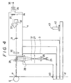
- Figure 3 is a side view showing the structures of the light receiving section 2 and the alignment index projection optical system located beneath this section.
- the part indicated by the reference numeral 2′ which is not illustrated in Figure 1, is an optical system for producing and projecting an index for use in alignment.
- the optical system 2′ comprises an alignment light source 22, alignment index plate 23 and a lens 24.
- the beam emitted by the alignment light source 22 should preferably be of a different color than the color of the laser beam produced by the laser beam projection section 1. The reason for this will be explained later.
- the optical system 2′ is coupled with the optical system of the light receiving section 2 by the beam splitter 16, and an image of the index of the alignment index plate 23 is formed at the convergence point P in the eye under examination E.
- the output of the photomultiplier 20 of the light receiving section 2 is input to the counter 53 shown in Figure 2 via an amplifier 21.
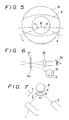
- Figure 4 is an overall side view of the structure of the apparatus, including the slit beam projection section 3 and the observation section 4.
- the slit beam projection section 3 and the observation section 4 are supported on respective L-shaped frames, which are in turn supported so as each to be rotatable in a horizontal plane about a shaft 40 rising from a platform 41.
- the platform 41 can be moved as a whole over the surface of a base (not shown) for the purpose of aligning the apparatus such that the axis of the shaft 40 passes through the convergence point P within the eye under examination E.
- the tip of the joy stick 42 has a switch 43 for controlling insertion/extraction or opening/closing of the shutter S2 and a shutter S1 of the slit beam projection section 3.
- the structure of this type of operation system is known to the art and will not be explained in detail here.
- the slit beam projection section 3 comprises a light source 25, a lens 26, a slit plate 27, the shutter S1, a lens 28 and the prism 29.
- the slit beam projection section 3 forms an image of the slit of the slit plate 27 at the convergence point P in the eye under examination E. This slit image illuminates the region surrounding the convergence point P of the laser beam from laser beam projection section 1, facilitating confirmation of the position of the convergence point P.
- the slit beam projection section 3 can rotate about the shaft 40 independently of the other sections, and specifically independently of the observation section 4, the apparatus can be used as a slit lamp microscope. In this case, the eye under examination can be observed in section through the observation section 4 using the slit beam.
- Figure 4 shows the structure relating to the observation section 4 in the vicinity of the optical axis on the left side of the observation section, where the alignment confirmation index plate 37 is provided.
- the reference numeral 36 in Figure 4 indicates the eye of the person operating the apparatus.
- the alignment light source 22 to illuminate the alignment index plate 23 (which is of pinhole or like configuration), whereby the index is projected in the direction of the eye under examination E via the optical system of the light receiving section 2 (namely, via the beam splitter 16 and the lens 15).
- Figure 5 shows the image observed through the observation section 4 when the eye under examination E and the apparatus are properly positioned within a horizontal plane.
- the reference symbol L designates the laser beam produced by the laser beam projection section 1 and the reference symbol A designates the light beam from the optical system 2′ built in the light receiving section 2.
- the laser beam L and the alignment beam A intersect at an angle of about 90 degrees within the horizontal plane, meaning that the cornea of the eye under examination E receives the beams at angles of 45 degrees from left and right.
- light is scattered by the cornea, as indicated by the reference symbols a and b . If the positions of the light scattering points a and b coincide with predetermined positions within the field R of the observation section 4, it is judged that the alignment of the eye under examination E and the apparatus has been achieved.
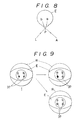
- the image observed through the observation section 4 is such as shown on the right side in Figure 9.
- the state shown on the left side of Figure 9 is the same as that shown in Figure 5 and is thus the image at the time of proper alignment.
- the state shown at the upper right of Figure 9 is that observed when the distance between the eye E and the apparatus along the x-axis shown in Figure 7 is too short and the position of the light scattering point b becomes offset to the outside
- the state shown at the lower right is that observed when the distance between the eye E and the apparatus along the y-axis in the same figure is too short and only the light scattering point a becomes offset to the outside.
- the alignment confirmation index plate 37 that is provided at the position of one of the field stops 34 is set in position in advance, as shown in Figure 6.
- the alignment confirmation index plate 37 is constituted of, for example, optical glass and has two pairs of cross-hairs, as also shown in Figure 6.
- the alignment beam A is cut by the interference filter 17 provided in the light receiving section 2 and does not reach the photomultiplier 20, leaving the alignment light source 22 on constantly does not cause any problems.
- no interference filter 17 it suffices to turn off the alignment light source 22 when measurement is being conducted.
- a light source e.g. an LED
- a laser emitting red light it becomes easy to distinguish the scattered lights resulting from the respective beams.
- this arrangement is also useful as regards judging whether or not the measurement was carried out accurately.
- the convergence point of (for example) the green light represents the image point of the mask 19.
- the convergence point of the laser beam and the convergence point of the alignment beam A should coincide at the convergence point P (where the beams intersect at 90 degrees) and if they do not, this indicates an apparatus setting error (or a malfunction).
- the shutter S1 will close and the shutter S2 will open so that the light of the laser beam produced by the laser beam projection section 1 which is scattered by protein in the anterior chamber will enter into and be measured by the light receiving section 2, making it possible to measure the protein concentration in the anterior chamber of the eye under examination.
- a laser beam is directed from the laser beam projection section 1 to the convergence point P within the eye under examination E, while the scattered light in the vicinity of the convergence point P is received by the light receiving section 2.
- the output of the photomultiplier 20 is passed through the amplifier 21 to the counter 53 connected with the controller 51.
- the intensity of the scattered light is represented and counted as the number of pulses per unit time.
- the count data of the counter 53 namely the number of the sampling and the total count, are stored at a predetermined memory region in the memory 52 once every time unit.
- the controller 51 carries out computations on the basis of this measurement data stored in the memory 52, whereby the protein concentration in the anterior chamber is determined. As the processing for this determination is well known, it will not be explained here.
- the above-described embodiment is arranged such that the alignment between the eye under examination E and the apparatus can be detected from whether or not the points at which the lights from the laser and alignment beams are scattered coincide with predetermined positions within the observation field of the observation optical system. As a result, the alignment between the eye under examination and the apparatus can be carried out simply and reliably.
- the various sections of the apparatus according to the foregoing embodiment can be made compact, and the laser beam projection section 1 and the light receiving section 2 can be readily attached to the observation section 4 to combine these sections into an integrated unit.
- the laser beam projection section and the slit beam projection section are integrated in one unit and the light receiving section and the observation section are integrated in another, and since light scattered at 90 degrees to the side is employed, observation from the observation section is limited to the 90-degree direction. This makes it impossible to use the apparatus as a slit lamp microscope.
- the slit beam projection section 3 can be rotated independently of the laser beam projection section 1 and the observation section 4 to which the light receiving section 2 is attached. Therefore, the apparatus is fully utilizable as a slit lamp microscope.
- the conventional practice has been to use a beam splitter for bringing the optical axes of the slit beam and the laser beam into registration, there has been a problem of a reduction in the light quantity in the slit and laser beams.
- the loss of slit beam light is reduced by separating the slit beam projection section and the laser beam illumination section.
- the observation section 4 by separating the light receiving section 2 and the observation section 4, a brighter image can be viewed through the observation section, while making it easier to judge the alignment and observe the eye under examination.
- the observation is also facilitated by the fact that the observation section 4 can be set directly in front of the eye under examination.
- the interference filter with a peak wavelength corresponding to the wavelength of the laser beam has been inserted into the light receiving section, the measurement need not be carried out in a dark room as has been required in the past but can be conducted in a semi-dark room.
- the optical axis of the laser beam and the optical axis at the eye under examination of the optical system 2′ included in the light receiving section meet at an angle of about 90 degrees within a horizontal plane including the eye under examination E. Setting the angle at this value enables the judgment regarding alignment illustrated in Figures 5 to 9 to be made with maximum sensitivity.
- the angle of intersection between the optical axis of the laser beam and that of the optical system 2′ can be set at a value other than 90 degrees.
Landscapes
- Life Sciences & Earth Sciences (AREA)
- Health & Medical Sciences (AREA)
- Medical Informatics (AREA)
- Biophysics (AREA)
- Ophthalmology & Optometry (AREA)
- Engineering & Computer Science (AREA)
- Biomedical Technology (AREA)
- Heart & Thoracic Surgery (AREA)
- Physics & Mathematics (AREA)
- Molecular Biology (AREA)
- Surgery (AREA)
- Animal Behavior & Ethology (AREA)
- General Health & Medical Sciences (AREA)
- Public Health (AREA)
- Veterinary Medicine (AREA)
- Eye Examination Apparatus (AREA)
Claims (5)
- Appareil de mesure ophtalmologique dans lequel un faisceau laser est dirigé dans un oeil en cours d'examen et une valeur de mesure est délivrée à partir de l'état de diffusion du faisceau laser à l'intérieur de l'oeil en cours d'examen, comprenant une partie (1) de projection du faisceau laser pour concentrer un faisceau laser produit par une source de faisceau laser (5) sur un point (P) déterminé d'avance de la chambre antérieure d'un oeil en cours d'examen, une partie de réception de la lumière (2) équipée d'un élément de conversion photoélectrique (20) pour recevoir la lumière laser dispersée par l'oeil en cours d'examen, une partie (2') de projection d'un repère d'alignement pour former, en un point déterminé d'avance, à l'intérieur de l'oeil en cours d'examen, un repère d'alignement (23) qui doit servir à juger l'alignement entre l'appareil et l'oeil en cours d'examen, la partie (2') de projection du repère d'alignement et la partie recevant la lumière (2) ayant au moins une partie de leur trajet optique en commun, une partie d'observation (4) pour observer l'état d'incidence du faisceau laser et de la lumière de l'image du repère d'alignement sur l'oeil en cours d'examen et un moyen (42) pour commander mécaniquement la position relative entre l'oeil en cours d'examen et l'appareil pour les amener tous les deux à être convenablement alignés en position en faisant en sorte que les points de diffusion de la lumière (a, b), formés sur l'oeil en cours d'examen par le faisceau laser et par la lumière de l'image du repère d'alignement, prennent des positions déterminées d'avance dans le champ de la partie d'observation.
- Appareil selon la revendication 1, comprenant, en outre, dans la partie d'observation (4), des repères (37) pour indiquer les positions dans un champ de vision de la partie d'observation qui sont prises par les points de diffusion de la lumière (a, b) formés sur la cornée de l'oeil en cours d'examen par le faisceau laser et la lumière de l'image du repère d'alignement lorsque les positions relatives de l'appareil et de l'oeil en cours d'examen sont alignées comme déterminé d'avance.
- Appareil selon la revendication 1 ou 2, dans lequel le faisceau laser (L) et la lumière (A) de l'image du repère d'alignement ont des couleurs différentes.
- Appareil selon l'une quelconque des revendications 1 à 3, comprenant en outre une partie (3) de projection d'un faisceau à travers une fente équipée d'une source lumineuse (25) pour projeter l'image d'un faisceau traversant une fente sur l'oeil en cours d'examen, la partie (3) de projection du faisceau à travers la fente comportant des moyens pour se placer elle-même par rapport à l'oeil en cours d'examen indépendamment de la partie de projection du faisceau laser (1), de la partie recevant la lumière (2), de la partie (2') de projection d'un repère d'alignement et de la partie d'observation (4).
- Appareil selon l'une quelconque des revendications 1 à 4, dans lequel la source de faisceau laser (5) est un laser à semi-conducteurs.
Applications Claiming Priority (2)
| Application Number | Priority Date | Filing Date | Title |
|---|---|---|---|
| JP228485/88 | 1988-09-14 | ||
| JP63228485A JPH0277228A (ja) | 1988-09-14 | 1988-09-14 | 眼科測定装置 |
Publications (2)
| Publication Number | Publication Date |
|---|---|
| EP0360397A1 EP0360397A1 (fr) | 1990-03-28 |
| EP0360397B1 true EP0360397B1 (fr) | 1994-05-04 |
Family
ID=16877206
Family Applications (1)
| Application Number | Title | Priority Date | Filing Date |
|---|---|---|---|
| EP89307846A Expired - Lifetime EP0360397B1 (fr) | 1988-09-14 | 1989-08-02 | Appareil de mesure d'ophtalmoscope |
Country Status (4)
| Country | Link |
|---|---|
| US (1) | US5013146A (fr) |
| EP (1) | EP0360397B1 (fr) |
| JP (1) | JPH0277228A (fr) |
| DE (1) | DE68915093T2 (fr) |
Families Citing this family (8)
| Publication number | Priority date | Publication date | Assignee | Title |
|---|---|---|---|---|
| JPH0282938A (ja) * | 1988-09-19 | 1990-03-23 | Topcon Corp | 眼科用測定装置 |
| DE19710906B4 (de) * | 1997-03-15 | 2004-02-19 | Carl Zeiss | Operationsmikroskop mit einer Pupillenlageerffassungsanordnung |
| JP4408640B2 (ja) * | 2003-03-17 | 2010-02-03 | 興和株式会社 | 眼科測定装置 |
| ES2617061T3 (es) * | 2006-04-11 | 2017-06-15 | Cognoptix, Inc | Procesamiento de imágenes oculares |
| PL2268193T3 (pl) * | 2008-03-27 | 2017-07-31 | Cognoptix, Inc. | Obrazowanie oczu w celu wykrywania chorób neurodegeneracyjnych |
| DE102008051147A1 (de) * | 2008-10-10 | 2010-04-15 | Carl Zeiss Meditec Ag | Anordnung und Verfahren zur Aufnahme und Auswertung von Spaltbildern überwiegend transparenter Medien, insbesondere im Auge |
| AU2011292233B2 (en) | 2010-08-16 | 2015-05-21 | Cognoptix, Inc. | System and method for detecting amyloid proteins |
| WO2025235677A1 (fr) * | 2024-05-08 | 2025-11-13 | Oregon Health & Science University | Tomographie stéréo de l'œil antérieur |
Family Cites Families (5)
| Publication number | Priority date | Publication date | Assignee | Title |
|---|---|---|---|---|
| JPS5843090B2 (ja) * | 1977-04-12 | 1983-09-24 | キヤノン株式会社 | 調整システムを備えた眼科装置 |
| US4702576A (en) * | 1985-09-27 | 1987-10-27 | Cambridge Instruments Inc. | Ocular scattering analyzer |
| JPH0624509B2 (ja) * | 1986-09-24 | 1994-04-06 | 株式会社トプコン | 眼科器械の作動距離整準用光学系 |
| EP0296769B1 (fr) * | 1987-06-25 | 1994-08-24 | Kowa Company, Ltd. | Procédé et dispositif destinés au diagnostic de maladies oculaires |
| JPS6417623A (en) * | 1987-07-14 | 1989-01-20 | Kowa Co | Alignment apparatus in opthalmic apparatus |
-
1988
- 1988-09-14 JP JP63228485A patent/JPH0277228A/ja active Pending
-
1989
- 1989-08-02 EP EP89307846A patent/EP0360397B1/fr not_active Expired - Lifetime
- 1989-08-02 DE DE68915093T patent/DE68915093T2/de not_active Expired - Fee Related
- 1989-08-18 US US07/396,639 patent/US5013146A/en not_active Expired - Fee Related
Also Published As
| Publication number | Publication date |
|---|---|
| US5013146A (en) | 1991-05-07 |
| JPH0277228A (ja) | 1990-03-16 |
| DE68915093T2 (de) | 1994-09-15 |
| DE68915093D1 (de) | 1994-06-09 |
| EP0360397A1 (fr) | 1990-03-28 |
Similar Documents
| Publication | Publication Date | Title |
|---|---|---|
| JPH1075931A (ja) | 眼底検査装置 | |
| JP2854657B2 (ja) | 眼科測定装置 | |
| JP4408640B2 (ja) | 眼科測定装置 | |
| EP0360397B1 (fr) | Appareil de mesure d'ophtalmoscope | |
| US4950068A (en) | Ophthalmic disease detection apparatus | |
| JP4267133B2 (ja) | 眼屈折力測定装置 | |
| EP0292216B1 (fr) | Dispositif de détection de maladies oculaires | |
| US4813778A (en) | Ophthalmic positioning apparatus | |
| EP0380197B1 (fr) | Appareil d'opthalmoscope | |
| JP2000245698A (ja) | 眼屈折力測定装置 | |
| EP0469770B1 (fr) | Appareil de mesure ophtalmologique | |
| EP0189350B1 (fr) | Appareil de mesure de la réfraction des yeux | |
| EP0380260A2 (fr) | Dispositif de mesure destiné à l'examen ophtalmologique | |
| EP0380221A2 (fr) | Dispositif de mesure destiné à l'examen ophtalmologique | |
| US6302850B1 (en) | Fundus blood flow metering method | |
| JP3518927B2 (ja) | 眼科装置 | |
| JPH09108185A (ja) | 眼科装置 | |
| JP3015042B2 (ja) | 手持ち眼屈折計 | |
| JPH08289874A (ja) | 眼底カメラ | |
| JP4700785B2 (ja) | 眼科装置 | |
| JP2938488B2 (ja) | 手術用顕微鏡 | |
| JPH06327634A (ja) | 眼科装置 | |
| JPS61220626A (ja) | 非接触式眼圧計 | |
| JPH0554325B2 (fr) | ||
| JP3497006B2 (ja) | 眼科装置 |
Legal Events
| Date | Code | Title | Description |
|---|---|---|---|
| PUAI | Public reference made under article 153(3) epc to a published international application that has entered the european phase |
Free format text: ORIGINAL CODE: 0009012 |
|
| AK | Designated contracting states |
Kind code of ref document: A1 Designated state(s): CH DE FR GB IT LI |
|
| 17P | Request for examination filed |
Effective date: 19900831 |
|
| 17Q | First examination report despatched |
Effective date: 19921207 |
|
| GRAA | (expected) grant |
Free format text: ORIGINAL CODE: 0009210 |
|
| AK | Designated contracting states |
Kind code of ref document: B1 Designated state(s): CH DE FR GB IT LI |
|
| ITF | It: translation for a ep patent filed | ||
| REF | Corresponds to: |
Ref document number: 68915093 Country of ref document: DE Date of ref document: 19940609 |
|
| ET | Fr: translation filed | ||
| PGFP | Annual fee paid to national office [announced via postgrant information from national office to epo] |
Ref country code: GB Payment date: 19940725 Year of fee payment: 6 |
|
| PG25 | Lapsed in a contracting state [announced via postgrant information from national office to epo] |
Ref country code: LI Effective date: 19940831 Ref country code: CH Effective date: 19940831 |
|
| PLBE | No opposition filed within time limit |
Free format text: ORIGINAL CODE: 0009261 |
|
| STAA | Information on the status of an ep patent application or granted ep patent |
Free format text: STATUS: NO OPPOSITION FILED WITHIN TIME LIMIT |
|
| 26N | No opposition filed | ||
| PG25 | Lapsed in a contracting state [announced via postgrant information from national office to epo] |
Ref country code: FR Effective date: 19950428 |
|
| REG | Reference to a national code |
Ref country code: CH Ref legal event code: PL |
|
| PG25 | Lapsed in a contracting state [announced via postgrant information from national office to epo] |
Ref country code: DE Effective date: 19950503 |
|
| REG | Reference to a national code |
Ref country code: FR Ref legal event code: ST |
|
| PG25 | Lapsed in a contracting state [announced via postgrant information from national office to epo] |
Ref country code: GB Effective date: 19950802 |
|
| GBPC | Gb: european patent ceased through non-payment of renewal fee |
Effective date: 19950802 |
|
| PG25 | Lapsed in a contracting state [announced via postgrant information from national office to epo] |
Ref country code: IT Free format text: LAPSE BECAUSE OF NON-PAYMENT OF DUE FEES;WARNING: LAPSES OF ITALIAN PATENTS WITH EFFECTIVE DATE BEFORE 2007 MAY HAVE OCCURRED AT ANY TIME BEFORE 2007. THE CORRECT EFFECTIVE DATE MAY BE DIFFERENT FROM THE ONE RECORDED. Effective date: 20050802 |