EP0360122A2 - Générateur du deuxième harmonique et système traitant des informations en se servant de ce générateur - Google Patents
Générateur du deuxième harmonique et système traitant des informations en se servant de ce générateur Download PDFInfo
- Publication number
- EP0360122A2 EP0360122A2 EP89116784A EP89116784A EP0360122A2 EP 0360122 A2 EP0360122 A2 EP 0360122A2 EP 89116784 A EP89116784 A EP 89116784A EP 89116784 A EP89116784 A EP 89116784A EP 0360122 A2 EP0360122 A2 EP 0360122A2
- Authority
- EP
- European Patent Office
- Prior art keywords
- light
- waveguide
- harmonic
- optical
- generally
- Prior art date
- Legal status (The legal status is an assumption and is not a legal conclusion. Google has not performed a legal analysis and makes no representation as to the accuracy of the status listed.)
- Granted
Links
Images


Classifications
-
- G—PHYSICS
- G11—INFORMATION STORAGE
- G11B—INFORMATION STORAGE BASED ON RELATIVE MOVEMENT BETWEEN RECORD CARRIER AND TRANSDUCER
- G11B7/00—Recording or reproducing by optical means, e.g. recording using a thermal beam of optical radiation by modifying optical properties or the physical structure, reproducing using an optical beam at lower power by sensing optical properties; Record carriers therefor
- G11B7/12—Heads, e.g. forming of the optical beam spot or modulation of the optical beam
- G11B7/135—Means for guiding the beam from the source to the record carrier or from the record carrier to the detector
- G11B7/1398—Means for shaping the cross-section of the beam, e.g. into circular or elliptical cross-section
-
- G—PHYSICS
- G02—OPTICS
- G02B—OPTICAL ELEMENTS, SYSTEMS OR APPARATUS
- G02B6/00—Light guides; Structural details of arrangements comprising light guides and other optical elements, e.g. couplings
- G02B6/10—Light guides; Structural details of arrangements comprising light guides and other optical elements, e.g. couplings of the optical waveguide type
- G02B6/12—Light guides; Structural details of arrangements comprising light guides and other optical elements, e.g. couplings of the optical waveguide type of the integrated circuit kind
- G02B6/122—Basic optical elements, e.g. light-guiding paths
-
- G—PHYSICS
- G02—OPTICS
- G02B—OPTICAL ELEMENTS, SYSTEMS OR APPARATUS
- G02B6/00—Light guides; Structural details of arrangements comprising light guides and other optical elements, e.g. couplings
- G02B6/24—Coupling light guides
- G02B6/26—Optical coupling means
- G02B6/34—Optical coupling means utilising prism or grating
-
- G—PHYSICS
- G02—OPTICS
- G02B—OPTICAL ELEMENTS, SYSTEMS OR APPARATUS
- G02B6/00—Light guides; Structural details of arrangements comprising light guides and other optical elements, e.g. couplings
- G02B6/24—Coupling light guides
- G02B6/42—Coupling light guides with opto-electronic elements
- G02B6/4201—Packages, e.g. shape, construction, internal or external details
- G02B6/4204—Packages, e.g. shape, construction, internal or external details the coupling comprising intermediate optical elements, e.g. lenses, holograms
- G02B6/4206—Optical features
-
- G—PHYSICS
- G02—OPTICS
- G02F—OPTICAL DEVICES OR ARRANGEMENTS FOR THE CONTROL OF LIGHT BY MODIFICATION OF THE OPTICAL PROPERTIES OF THE MEDIA OF THE ELEMENTS INVOLVED THEREIN; NON-LINEAR OPTICS; FREQUENCY-CHANGING OF LIGHT; OPTICAL LOGIC ELEMENTS; OPTICAL ANALOGUE/DIGITAL CONVERTERS
- G02F1/00—Devices or arrangements for the control of the intensity, colour, phase, polarisation or direction of light arriving from an independent light source, e.g. switching, gating or modulating; Non-linear optics
- G02F1/35—Non-linear optics
- G02F1/37—Non-linear optics for second-harmonic generation
- G02F1/377—Non-linear optics for second-harmonic generation in an optical waveguide structure
-
- G—PHYSICS
- G11—INFORMATION STORAGE
- G11B—INFORMATION STORAGE BASED ON RELATIVE MOVEMENT BETWEEN RECORD CARRIER AND TRANSDUCER
- G11B7/00—Recording or reproducing by optical means, e.g. recording using a thermal beam of optical radiation by modifying optical properties or the physical structure, reproducing using an optical beam at lower power by sensing optical properties; Record carriers therefor
- G11B7/12—Heads, e.g. forming of the optical beam spot or modulation of the optical beam
- G11B7/135—Means for guiding the beam from the source to the record carrier or from the record carrier to the detector
- G11B7/1372—Lenses
- G11B7/1376—Collimator lenses
-
- G—PHYSICS
- G02—OPTICS
- G02F—OPTICAL DEVICES OR ARRANGEMENTS FOR THE CONTROL OF LIGHT BY MODIFICATION OF THE OPTICAL PROPERTIES OF THE MEDIA OF THE ELEMENTS INVOLVED THEREIN; NON-LINEAR OPTICS; FREQUENCY-CHANGING OF LIGHT; OPTICAL LOGIC ELEMENTS; OPTICAL ANALOGUE/DIGITAL CONVERTERS
- G02F1/00—Devices or arrangements for the control of the intensity, colour, phase, polarisation or direction of light arriving from an independent light source, e.g. switching, gating or modulating; Non-linear optics
- G02F1/35—Non-linear optics
- G02F1/37—Non-linear optics for second-harmonic generation
- G02F1/372—Means for homogenizing the output beam
-
- G—PHYSICS
- G02—OPTICS
- G02F—OPTICAL DEVICES OR ARRANGEMENTS FOR THE CONTROL OF LIGHT BY MODIFICATION OF THE OPTICAL PROPERTIES OF THE MEDIA OF THE ELEMENTS INVOLVED THEREIN; NON-LINEAR OPTICS; FREQUENCY-CHANGING OF LIGHT; OPTICAL LOGIC ELEMENTS; OPTICAL ANALOGUE/DIGITAL CONVERTERS
- G02F1/00—Devices or arrangements for the control of the intensity, colour, phase, polarisation or direction of light arriving from an independent light source, e.g. switching, gating or modulating; Non-linear optics
- G02F1/35—Non-linear optics
- G02F1/37—Non-linear optics for second-harmonic generation
- G02F1/374—Cherenkov radiation
-
- G—PHYSICS
- G02—OPTICS
- G02F—OPTICAL DEVICES OR ARRANGEMENTS FOR THE CONTROL OF LIGHT BY MODIFICATION OF THE OPTICAL PROPERTIES OF THE MEDIA OF THE ELEMENTS INVOLVED THEREIN; NON-LINEAR OPTICS; FREQUENCY-CHANGING OF LIGHT; OPTICAL LOGIC ELEMENTS; OPTICAL ANALOGUE/DIGITAL CONVERTERS
- G02F1/00—Devices or arrangements for the control of the intensity, colour, phase, polarisation or direction of light arriving from an independent light source, e.g. switching, gating or modulating; Non-linear optics
- G02F1/35—Non-linear optics
- G02F1/37—Non-linear optics for second-harmonic generation
- G02F1/377—Non-linear optics for second-harmonic generation in an optical waveguide structure
- G02F1/383—Non-linear optics for second-harmonic generation in an optical waveguide structure of the optical fibre type
Definitions
- the present invention relates to a second harmonic generator which utilizes Cherenkov radiation that is useful as a source of coherent short-wave light.
- Such light is useful for optical reading or recording, such as in optical disks, laser printers or color printers.
- Such devices benefit from light having a higher frequency, and correspondingly, a lower wavelength.
- Shorter wavelength light provides for example, increased resolution in laser printers, and increased data density in optical disks.
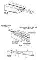
- Fig. 4 Such an earlier method is shown in Fig. 4.
- the substrate of the waveguide consisted simply of a block having a flat surface.
- the beam passing through the substrate develops large aberration, but no means for correcting the aberration had ever been employed.
- the subject invention remedies all the above-referred problems, and others, and recognizes in that the above-mentioned technologies, a problem resided in that attention had not been sufficiently given to beam formation.
- the present invention provides a second harmonic wave generator which is compact in size, which is capable of directly modulating the light intensity, and which generates a coherent beam of short wavelengths that is collimated, maintaining a high flatness.
- an optical system is added in which an aberration correction function or a beam shaping function is given to the waveguide substrate or to the cladded portion of the fiber in order to improve the flatness of the wave front formed by the beam that is emitted, and to focus the beam through a lens into a spot of a diffraction limit.
- the second harmonic Cherenkov beam obtained from the fibrous waveguide made of non-linear optical material has the wave front, i.e., has an equiphase front of wave motion, that assumes a conical shape with the fiber as a center line.
- the presence of ray at right angles with the conical wave front is apparent from Malus's theory. However, it is one of the objects of the present invention to have these rays travel in parallel with each other along the center lines of the fibers.
- First means therefor is based on Snell's law that applies when a ray of light passes through a boundary of media having dissimilar indices of refraction. That is, a first point of the present invention is to use a conical prism as, will be described in more detail below, to convert a conical wave front into a parallel plane wave.
- a conical prism as, will be described in more detail below, to convert a conical wave front into a parallel plane wave.
- Such a means is suitably applied to the fiber-type Cherenkov beam.
- the system is also suitably applied to a waveguide type Cherenkov beam which appears as if the fiber-type Cherenkov beam is divided into two. In this case, the cone is halved, as a matter of course.
- a second embodiment of the present invention applies the law of reflection, in contrast with the application of refraction utilized above. That is, the fiber, the clad of the waveguide, or the substrate, is fashioned such that it has a totally internal reflective surface with a conical or hemi-conical shape, expanding in the direction in which the ray of light travels. Further, the angle relative to the center line of the conical axis is so defined that the ray of light is totally reflected, and all becomes in parallel with the waveguide.
- a third embodiment of the present invention provides that fiber clads formed in a conical shape, as mentioned above, or the second harmonic Cherenkov beam generating portions formed in the waveguide substrate, are arranging in a plural number. These were thus far arranged singly. The lasing phases among the Cherenkov beams are then coupled together to obtain coherent beams.
- This embodiment provides an even greater optical output. That is, by adding the first point or the second point and the third point, it is made possible to realize a second harmonic optical source capable of focusing a ray into a single spot, close to the diffraction limit, yet maintaining a large output.
- the Cherenkov beam becomes a parallel beam after the refraction and can be focused upon one point.
- Fig. 1 illustrates an embodiment wherein a semiconductor laser 1 serves as a fundamental optical source.
- the beam from the fundamental optical source is focused through a lens 2, imaged, and communicated to a face of a fiber 3 comprised of a non-linear optical material which has a characteristic response of polarization to an induced electric field.
- a polarization wave is then induced in the fiber 3.
- a polarization wave is radiated as a so-called Cherenkov radiation 4 which is, usually, a blue light having a wavelength one-half that of the fundamental input light, maintaining an angle ⁇ .
- Cherenkov radiation 4 which is, usually, a blue light having a wavelength one-half that of the fundamental input light, maintaining an angle ⁇ .
- Such a beam diverges with its equiphase surface being in a conical shape.
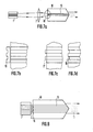
- Fig. 3 illustrates a third embodiment of the present invention.
- waveguide 9 for generating second harmonics is formed on a non-linear optical crystal 10, and Cherenkov radiation beam is collimated through an optical system. That is, the beam from the semiconductor laser 1 is focused and imaged through a lens 2, and is permitted to be incident upon the incident face of the waveguide 9.
- the fundamental light generates polarization wave in the waveguide 9 and whereby the Cherenkov beam is radiated maintaining an angle ⁇ with a lateral divergence angle ⁇ .
- the front (exit face) of the substrate 10 of the waveguide 9 assumes a conical shape that is cut into a half as shown in Fig. 3(b).
- a vertical angle ⁇ of the conical shape is calculated by the method described above.
- a beam 11 that is collimated as a parallel light.
- the beam 11 may have an anisotropic distribution of intensities.
- Such a beam can be focused into one point of a diffraction limit.
- Fig. 4 is a diagram illustrating a conventional example lacking any aberration correction for the Cherenkov radiated second harmonics; i.e., blue light is only obtained. This example cannot be applied to a diffraction limit optical system such as optical disks or laser printers.
- the aforementioned embodiments were to obtain a parallel beam by utilizing a first point of the present invention, i.e., by utilizing the law of refraction of rays.
- Described below is an embodiment for collimating the Cherenkov beam by the law of reflection. That is, as shown in Fig. 5, the Cherenkov beam is once totally reflected by the back face of the waveguide substrate 10. The inclination of the back surface is then so determined that the ray of light reflected becomes parallel with the waveguide 9. As this holds true for all Cherenkov beams, the reflected beams must become parallel in all cross sections that include the waveguides 9. For this purpose, therefore, the outer face must have a conical shape as shown in Fig.5(a).
- the distribution of intensities can also be shaped.
- the length of the waveguide 9 and the radius of the cone it is possible to form a beam 14 that it has nearly an isotropic intensity distribution.
- the beam shaping is in no way limited to this method only, but the method of utilizing the prism described with reference to Fig. 3 can also be applied.
- Described below is a method of increasing the optical output of the secondary harmonic Cherenkov beam that is formed by collimating the thus obtained highly parallel plane waves.
- a beam from a semiconductor laser 1 is focused through a lens 2 to form an image which is then permitted to be incident on the waveguides 15 arranged like an array.
- the waveguide substrate 10 has a conical front face or outer face as shown in Figs. 3 or 5.
- Such fabrication makes it possible to obtain a second harmonic output greater than that of when a single waveguide is used. It need not be mentioned that enhanced effects are obtained even when semiconductor lasers are arranged like an array to form a fundamental optical source having a large output.
- the fibers are also arranged like an array (Fig. 6(c)). In either case, the phases must be coupled among the waveguides or fibers. Accordingly, the waveguide array or fiber array generates second harmonic Cherenkov beams coherently relative to each other.
- a phase corrector 16 is installed between the semiconductor laser array and the waveguide array for generating secondary harmonics, as shown in the embodiment of Fig.7(a) or (b).
- the phase corrector 17 or 18 is formed on the face of the waveguide array as shown in the embodiment of Figs. 7(c) or 7(d). This functions to completely render uniform the phases of the laser beam incident upon the waveguide array. This makes it possible to render quite uniform the phases of second harmonics in the obtained Cherenkov beam.
- magnification (reduction ratio) of the lens 2 for forming the image is set to, for example, 1/2, the power density of the incident beam upon the waveguide array becomes four times as great, making it possible to obtain a high wavelength conversion efficiency, which is a feature of this embodiment.
- the semiconductor laser array 1 is directly coupled to the waveguide array in order to reduce the size of the whole second harmonic generator.
- Fig. 9 illustrates an embodiment in which the beam of large output and high quality obtained as described above is used as an optical source for recording and/or reading on or from an optical disk. That is, the beam from a second harmonic generator (source of blue light) 19 according to the present invention is permitted to pass through a beam splitter 20 and a mirror 21, and is focused into a tiny spot through a focusing lens 22 to record pits onto an optical disk 23. At this moment, the fundamental semiconductor laser is directly modulated in accordance with modulated signals to be recorded by a signal circuit 24. The pits recorded onto the optical disk 23 are read as intensity changes of light reflected from the optical disk. The light is reflected by the beam splitter 20, and is processed by a reproduced signal processing circuit 25.
- a second harmonic generator source of blue light
- Fig. 10 illustrates an embodiment in which the second harmonic generator 19 according to the present invention is used as an optical source for a laser beam printer. That is, the beam directly modulated by the recording signal circuit 26, is scanned by a polygonal mirror 27, and focused into a spot through a scanning lens 28 to scan on the photosensitive drum 29. A negative image formed on the photosensitive drum is transferred by a printing process onto a paper to effect the high-speed printing.
- the present invention teaches a system which deals with a Cherenkov-type waveguide or fiber device that generates second harmonics of a high conversion efficiency utilizing high optical power density and that enables phases to be easily adjusted.
- a source of short-wavelength coherent light in which a focusing optical source is formed as a unitary structure, such as was not possible thus far, that is small in size, that enables the intensity of light to be directly modified, and that generates coherent light of short wavelengths which is highly planarly collimated.
- the recording and reproduction can be effected with a wavelength one-half the conventional semiconductor laser wavelength. Therefore, the density for recording data becomes four times as great, or the light output that is required decreases to one-fourth.
- the optical source is applied to the laser printer that is shown in Fig. 10, the printing can be carried out in maintaining a resolution which is 4 times as high as that of conventional art. Sensitivity of the photosensitive drum increases, too. Therefore, the printing can be carried out under favorable conditions such as at high printing speeds.
- the optical source of short waves according to the present invention finds a wide range of applications including not only the aforementioned field of data processing but also the fields of displays and color printers.
- the conventional technology for generating second harmonics involves a problem in that the non-linear optical crystal is optically damaged. This stems from the fact that too much attention is given to a high conversion efficiency into the second harmonic and whereby the density of the fundamental light power becomes too great in the waveguide. Therefore, as optical damage develops in the waveguide or in the substrate, the light is absorbed in increased amounts and the output of the second harmonic decreases.
- the waveguides are arranged in a plural number in the form of an array, and the density of light power is suitably decreased to eliminate the problem of optical damage.
- Fig. 11 an embodiment providing improve efficiency in generation of a second harmonic wave will be described. It is generally well known that an external cavity resonator for a fundamental beam is effective for increasing efficiency of second harmonic wave generation. Such resonators are readily adaptable to the present invention.
- Fig. 11(a) illustrates a Fabry-Perot resonator 30.
- the resonator 30 is suitably either of the single or plural monolithic type.
- Fig. 11(b) illustrates incorporation of a Distributed Feedback type resonator 31 in a non-linear optical crystal. Combinations of the type illustrated in Fig. 11 will provide a good quality wavefront SHG beam with higher power. The increased power allows for higher data rate optical recording systems in such applications as optical discs and laser printers.
Landscapes
- Physics & Mathematics (AREA)
- Optics & Photonics (AREA)
- General Physics & Mathematics (AREA)
- Nonlinear Science (AREA)
- Engineering & Computer Science (AREA)
- Microelectronics & Electronic Packaging (AREA)
- Optical Head (AREA)
- Semiconductor Lasers (AREA)
- Lasers (AREA)
- Optical Recording Or Reproduction (AREA)
Applications Claiming Priority (2)
| Application Number | Priority Date | Filing Date | Title |
|---|---|---|---|
| JP232378/88 | 1988-09-19 | ||
| JP63232378A JP2738713B2 (ja) | 1988-09-19 | 1988-09-19 | 第2高調波発生装置 |
Publications (3)
| Publication Number | Publication Date |
|---|---|
| EP0360122A2 true EP0360122A2 (fr) | 1990-03-28 |
| EP0360122A3 EP0360122A3 (fr) | 1991-02-13 |
| EP0360122B1 EP0360122B1 (fr) | 1995-12-27 |
Family
ID=16938293
Family Applications (1)
| Application Number | Title | Priority Date | Filing Date |
|---|---|---|---|
| EP89116784A Expired - Lifetime EP0360122B1 (fr) | 1988-09-19 | 1989-09-11 | Générateur du deuxième harmonique et système traitant des informations en se servant de ce générateur |
Country Status (4)
| Country | Link |
|---|---|
| US (1) | US4972422A (fr) |
| EP (1) | EP0360122B1 (fr) |
| JP (1) | JP2738713B2 (fr) |
| DE (1) | DE68925254T2 (fr) |
Cited By (3)
| Publication number | Priority date | Publication date | Assignee | Title |
|---|---|---|---|---|
| EP0490291A1 (fr) * | 1990-12-14 | 1992-06-17 | Sumitomo Electric Industries, Ltd. | Dispositif de source de lumière |
| EP0490369A1 (fr) * | 1990-12-14 | 1992-06-17 | Sumitomo Electric Industries, Ltd. | Convertisseur de longueur d'onde |
| WO2014007386A1 (fr) * | 2012-07-03 | 2014-01-09 | Canon Kabushiki Kaisha | Générateur d'ondes térahertz, détecteur d'ondes térahertz, et dispositif de spectroscopie térahertz dans le domaine temporel |
Families Citing this family (14)
| Publication number | Priority date | Publication date | Assignee | Title |
|---|---|---|---|---|
| DE68926074T2 (de) * | 1988-07-26 | 1996-08-14 | Fuji Photo Film Co Ltd | Optische Wellenlängenkonverter-Einrichtung und optisches Wellenlängenkonverter-Modul |
| US5355246A (en) * | 1988-10-12 | 1994-10-11 | Fuji Electric Co., Ltd. | Wavelength conversion device |
| US5109462A (en) * | 1989-09-07 | 1992-04-28 | Sharp Kabushiki Kaisha | Light wavelength converter |
| US5117433A (en) * | 1989-11-27 | 1992-05-26 | Hitachi, Ltd. | Second harmonic generator for obtaining an aberration free plane wave and information processing system using the same |
| US5854870A (en) * | 1990-05-25 | 1998-12-29 | Hitachi, Ltd. | Short-wavelength laser light source |
| US5251060A (en) * | 1991-09-30 | 1993-10-05 | Sumitomo Electric Industries, Ltd. | Light-source unit |
| JPH06102545A (ja) * | 1992-09-04 | 1994-04-15 | Internatl Business Mach Corp <Ibm> | 波長変換装置 |
| DE10102592A1 (de) * | 2001-01-20 | 2002-07-25 | Deutsche Telekom Ag | Optik zur Einkopplung von Licht aus einer Lichtquelle in ein Medium |
| US7646546B1 (en) * | 2005-06-10 | 2010-01-12 | Cvi Laser, Llc | Anamorphic optical system providing a highly polarized laser output |
| JP2012053450A (ja) * | 2010-08-05 | 2012-03-15 | Canon Inc | テラヘルツ波発生素子、テラヘルツ波検出素子、テラヘルツ波発生装置、テラヘルツ波検出装置、テラヘルツ波測定装置、及びテラヘルツ波トモグラフィックイメージング装置 |
| JP2012068621A (ja) * | 2010-08-24 | 2012-04-05 | Canon Inc | テラヘルツ波発生素子、テラヘルツ波検出素子、及びテラヘルツ時間領域分光装置 |
| JP5870509B2 (ja) * | 2011-05-30 | 2016-03-01 | ソニー株式会社 | 光源装置、光学ピックアップ、記録装置 |
| JP5973774B2 (ja) * | 2012-04-27 | 2016-08-23 | 株式会社アドバンテスト | 電磁波放射装置 |
| JP6456078B2 (ja) | 2013-10-09 | 2019-01-23 | キヤノン株式会社 | テラヘルツ波発生素子、及び、テラヘルツ波検出素子 |
Citations (6)
| Publication number | Priority date | Publication date | Assignee | Title |
|---|---|---|---|---|
| US3297875A (en) * | 1962-06-28 | 1967-01-10 | Ibm | Optical traveling wave parametric devices |
| JPS61189524A (ja) * | 1985-02-19 | 1986-08-23 | Matsushita Electric Ind Co Ltd | 光波長変換装置 |
| JPS6315235A (ja) * | 1986-07-08 | 1988-01-22 | Fuji Photo Film Co Ltd | 光波長変換素子 |
| JPS63261545A (ja) * | 1987-04-20 | 1988-10-28 | Pioneer Electronic Corp | 光学式ピツクアツプ |
| EP0342523A2 (fr) * | 1988-05-14 | 1989-11-23 | Sumitomo Electric Industries, Ltd. | Génération de rayons parallèles de lumière à double fréquence utilisant une fibre optique |
| EP0352751A2 (fr) * | 1988-07-26 | 1990-01-31 | Fuji Photo Film Co., Ltd. | Dispositif de conversion de longueur d'onde optique et module convertisseur de longueur d'onde optique |
Family Cites Families (7)
| Publication number | Priority date | Publication date | Assignee | Title |
|---|---|---|---|---|
| JPS6118934A (ja) * | 1984-07-05 | 1986-01-27 | Matsushita Electric Ind Co Ltd | 光波長変換装置 |
| EP0254921B1 (fr) * | 1986-07-07 | 1993-12-15 | Fuji Photo Film Co., Ltd. | Dispositif de conversion de longueur d'onde optique et une méthode pour sa fabrication |
| JPS6344781A (ja) * | 1986-08-11 | 1988-02-25 | Sharp Corp | 高調波発生装置 |
| JPH0514538Y2 (fr) * | 1986-10-08 | 1993-04-19 | ||
| US4830447A (en) * | 1987-02-13 | 1989-05-16 | Fuji Photo Film Co., Ltd. | Optical wavelength conversion device |
| JPS63199328A (ja) * | 1987-02-16 | 1988-08-17 | Fuji Photo Film Co Ltd | 光波長変換素子 |
| JPH0227325A (ja) * | 1988-07-15 | 1990-01-30 | Matsushita Electric Ind Co Ltd | 光波長変換装置 |
-
1988
- 1988-09-19 JP JP63232378A patent/JP2738713B2/ja not_active Expired - Lifetime
-
1989
- 1989-09-11 DE DE68925254T patent/DE68925254T2/de not_active Expired - Fee Related
- 1989-09-11 EP EP89116784A patent/EP0360122B1/fr not_active Expired - Lifetime
- 1989-09-18 US US07/408,537 patent/US4972422A/en not_active Expired - Fee Related
Patent Citations (6)
| Publication number | Priority date | Publication date | Assignee | Title |
|---|---|---|---|---|
| US3297875A (en) * | 1962-06-28 | 1967-01-10 | Ibm | Optical traveling wave parametric devices |
| JPS61189524A (ja) * | 1985-02-19 | 1986-08-23 | Matsushita Electric Ind Co Ltd | 光波長変換装置 |
| JPS6315235A (ja) * | 1986-07-08 | 1988-01-22 | Fuji Photo Film Co Ltd | 光波長変換素子 |
| JPS63261545A (ja) * | 1987-04-20 | 1988-10-28 | Pioneer Electronic Corp | 光学式ピツクアツプ |
| EP0342523A2 (fr) * | 1988-05-14 | 1989-11-23 | Sumitomo Electric Industries, Ltd. | Génération de rayons parallèles de lumière à double fréquence utilisant une fibre optique |
| EP0352751A2 (fr) * | 1988-07-26 | 1990-01-31 | Fuji Photo Film Co., Ltd. | Dispositif de conversion de longueur d'onde optique et module convertisseur de longueur d'onde optique |
Non-Patent Citations (3)
| Title |
|---|
| PATENT ABSTRACTS OF JAPAN vol. 11, no. 15 (P-536)(2462), 16 January 1987; & JP-A-61 189 524 (MATSUSHITA ELECTRIC) 23.08.1986 * |
| PATENT ABSTRACTS OF JAPAN vol. 12, no. 220 (P-720)(3067), 23 June 1988; & JP-A-63 015 235 (FUJI PHOTO FILM) 22.01.1988 * |
| PATENT ABSTRACTS OF JAPAN vol. 13, no. 80 (P-832), 23 February 1989; & JP-A-63 261 545 (PIONEER ELECTRONIC) 28.10.1988 * |
Cited By (5)
| Publication number | Priority date | Publication date | Assignee | Title |
|---|---|---|---|---|
| EP0490291A1 (fr) * | 1990-12-14 | 1992-06-17 | Sumitomo Electric Industries, Ltd. | Dispositif de source de lumière |
| EP0490369A1 (fr) * | 1990-12-14 | 1992-06-17 | Sumitomo Electric Industries, Ltd. | Convertisseur de longueur d'onde |
| US5195159A (en) * | 1990-12-14 | 1993-03-16 | Sumitomo Electric Industries, Ltd. | Optical wavelength converter device |
| US5293444A (en) * | 1990-12-14 | 1994-03-08 | Sumitomo Electric Industries, Ltd. | Wavelength converter |
| WO2014007386A1 (fr) * | 2012-07-03 | 2014-01-09 | Canon Kabushiki Kaisha | Générateur d'ondes térahertz, détecteur d'ondes térahertz, et dispositif de spectroscopie térahertz dans le domaine temporel |
Also Published As
| Publication number | Publication date |
|---|---|
| DE68925254T2 (de) | 1996-07-25 |
| JPH0281035A (ja) | 1990-03-22 |
| DE68925254D1 (de) | 1996-02-08 |
| EP0360122A3 (fr) | 1991-02-13 |
| US4972422A (en) | 1990-11-20 |
| EP0360122B1 (fr) | 1995-12-27 |
| JP2738713B2 (ja) | 1998-04-08 |
Similar Documents
| Publication | Publication Date | Title |
|---|---|---|
| US4972422A (en) | Second harmonic generator and information processing system using the same | |
| US7408847B2 (en) | Integrated type optical head with sheet waveguide and light coupler | |
| US4770507A (en) | Prism optics and optical information processing apparatus | |
| EP0372345B1 (fr) | Source de lumière | |
| US5444567A (en) | Light control device | |
| US5117433A (en) | Second harmonic generator for obtaining an aberration free plane wave and information processing system using the same | |
| JPH0611750A (ja) | 光学装置及び光学式走査装置 | |
| EP0342523A2 (fr) | Génération de rayons parallèles de lumière à double fréquence utilisant une fibre optique | |
| US6317546B1 (en) | Optical waveguide device, and light source device and optical apparatus including the optical waveguide device | |
| JPH0451006B2 (fr) | ||
| US4959665A (en) | Laser printer with harmonic wave separation of the beam | |
| CA2057545C (fr) | Source lumineuse | |
| US5416877A (en) | Optical wavelength converter device and optical wavelength converter module | |
| US6785457B2 (en) | Optical waveguide device and coherent light source and optical apparatus using the same | |
| US5224193A (en) | First order mode frequency doubler system and method | |
| KR0149036B1 (ko) | 프린터용 방사 소스 | |
| EP0291184A2 (fr) | Dispositifs optiques pour enregistrement holographique | |
| US5119458A (en) | Fibre-type wavelength converison device | |
| JPH04507012A (ja) | レーザプリンタ用の多チャンネル集積型光モジュレータ | |
| Kataoka et al. | Laser printer optics with use of slant scanning of multiple beams | |
| JPH0973056A (ja) | 音響光学素子を用いた光学装置 | |
| JPH01107213A (ja) | 光導波路素子 | |
| JP3216399B2 (ja) | 多ビーム走査光記録装置 | |
| JP2605933B2 (ja) | 光束整形レンズおよび短波長レーザ光源 | |
| JPH05188339A (ja) | 光記録装置の光学系 |
Legal Events
| Date | Code | Title | Description |
|---|---|---|---|
| PUAI | Public reference made under article 153(3) epc to a published international application that has entered the european phase |
Free format text: ORIGINAL CODE: 0009012 |
|
| AK | Designated contracting states |
Kind code of ref document: A2 Designated state(s): DE FR GB |
|
| PUAL | Search report despatched |
Free format text: ORIGINAL CODE: 0009013 |
|
| 17P | Request for examination filed |
Effective date: 19901212 |
|
| AK | Designated contracting states |
Kind code of ref document: A3 Designated state(s): DE FR GB |
|
| 17Q | First examination report despatched |
Effective date: 19930416 |
|
| GRAA | (expected) grant |
Free format text: ORIGINAL CODE: 0009210 |
|
| AK | Designated contracting states |
Kind code of ref document: B1 Designated state(s): DE FR GB |
|
| REF | Corresponds to: |
Ref document number: 68925254 Country of ref document: DE Date of ref document: 19960208 |
|
| ET | Fr: translation filed | ||
| PG25 | Lapsed in a contracting state [announced via postgrant information from national office to epo] |
Ref country code: GB Effective date: 19960911 |
|
| PLBE | No opposition filed within time limit |
Free format text: ORIGINAL CODE: 0009261 |
|
| STAA | Information on the status of an ep patent application or granted ep patent |
Free format text: STATUS: NO OPPOSITION FILED WITHIN TIME LIMIT |
|
| 26N | No opposition filed | ||
| GBPC | Gb: european patent ceased through non-payment of renewal fee |
Effective date: 19960911 |
|
| PG25 | Lapsed in a contracting state [announced via postgrant information from national office to epo] |
Ref country code: DE Effective date: 19970603 |
|
| PG25 | Lapsed in a contracting state [announced via postgrant information from national office to epo] |
Ref country code: FR Effective date: 19970630 |
|
| REG | Reference to a national code |
Ref country code: FR Ref legal event code: ST |
|
| REG | Reference to a national code |
Ref country code: FR Ref legal event code: ST |