EP0359583A2 - Système de commande pour imprimante - Google Patents
Système de commande pour imprimante Download PDFInfo
- Publication number
- EP0359583A2 EP0359583A2 EP89309402A EP89309402A EP0359583A2 EP 0359583 A2 EP0359583 A2 EP 0359583A2 EP 89309402 A EP89309402 A EP 89309402A EP 89309402 A EP89309402 A EP 89309402A EP 0359583 A2 EP0359583 A2 EP 0359583A2
- Authority
- EP
- European Patent Office
- Prior art keywords
- carriage
- reflecting member
- light
- control system
- printer
- Prior art date
- Legal status (The legal status is an assumption and is not a legal conclusion. Google has not performed a legal analysis and makes no representation as to the accuracy of the status listed.)
- Granted
Links
Images


Classifications
-
- B—PERFORMING OPERATIONS; TRANSPORTING
- B41—PRINTING; LINING MACHINES; TYPEWRITERS; STAMPS
- B41J—TYPEWRITERS; SELECTIVE PRINTING MECHANISMS, i.e. MECHANISMS PRINTING OTHERWISE THAN FROM A FORME; CORRECTION OF TYPOGRAPHICAL ERRORS
- B41J11/00—Devices or arrangements of selective printing mechanisms, e.g. ink-jet printers or thermal printers, for supporting or handling copy material in sheet or web form
- B41J11/66—Applications of cutting devices
- B41J11/70—Applications of cutting devices cutting perpendicular to the direction of paper feed
- B41J11/706—Applications of cutting devices cutting perpendicular to the direction of paper feed using a cutting tool mounted on a reciprocating carrier
-
- Y—GENERAL TAGGING OF NEW TECHNOLOGICAL DEVELOPMENTS; GENERAL TAGGING OF CROSS-SECTIONAL TECHNOLOGIES SPANNING OVER SEVERAL SECTIONS OF THE IPC; TECHNICAL SUBJECTS COVERED BY FORMER USPC CROSS-REFERENCE ART COLLECTIONS [XRACs] AND DIGESTS
- Y10—TECHNICAL SUBJECTS COVERED BY FORMER USPC
- Y10T—TECHNICAL SUBJECTS COVERED BY FORMER US CLASSIFICATION
- Y10T83/00—Cutting
- Y10T83/162—With control means responsive to replaceable or selectable information program
- Y10T83/173—Arithmetically determined program
- Y10T83/175—With condition sensor
-
- Y—GENERAL TAGGING OF NEW TECHNOLOGICAL DEVELOPMENTS; GENERAL TAGGING OF CROSS-SECTIONAL TECHNOLOGIES SPANNING OVER SEVERAL SECTIONS OF THE IPC; TECHNICAL SUBJECTS COVERED BY FORMER USPC CROSS-REFERENCE ART COLLECTIONS [XRACs] AND DIGESTS
- Y10—TECHNICAL SUBJECTS COVERED BY FORMER USPC
- Y10T—TECHNICAL SUBJECTS COVERED BY FORMER US CLASSIFICATION
- Y10T83/00—Cutting
- Y10T83/444—Tool engages work during dwell of intermittent workfeed
- Y10T83/4539—Means to change tool position, or length or datum position of work- or tool-feed increment
- Y10T83/4559—With means to vary magnitude or base position of tool stroke
-
- Y—GENERAL TAGGING OF NEW TECHNOLOGICAL DEVELOPMENTS; GENERAL TAGGING OF CROSS-SECTIONAL TECHNOLOGIES SPANNING OVER SEVERAL SECTIONS OF THE IPC; TECHNICAL SUBJECTS COVERED BY FORMER USPC CROSS-REFERENCE ART COLLECTIONS [XRACs] AND DIGESTS
- Y10—TECHNICAL SUBJECTS COVERED BY FORMER USPC
- Y10T—TECHNICAL SUBJECTS COVERED BY FORMER US CLASSIFICATION
- Y10T83/00—Cutting
- Y10T83/768—Rotatable disc tool pair or tool and carrier
- Y10T83/7755—Carrier for rotatable tool movable during cutting
- Y10T83/7759—Unicyclic movement
-
- Y—GENERAL TAGGING OF NEW TECHNOLOGICAL DEVELOPMENTS; GENERAL TAGGING OF CROSS-SECTIONAL TECHNOLOGIES SPANNING OVER SEVERAL SECTIONS OF THE IPC; TECHNICAL SUBJECTS COVERED BY FORMER USPC CROSS-REFERENCE ART COLLECTIONS [XRACs] AND DIGESTS
- Y10—TECHNICAL SUBJECTS COVERED BY FORMER USPC
- Y10T—TECHNICAL SUBJECTS COVERED BY FORMER US CLASSIFICATION
- Y10T83/00—Cutting
- Y10T83/768—Rotatable disc tool pair or tool and carrier
- Y10T83/7755—Carrier for rotatable tool movable during cutting
- Y10T83/7763—Tool carrier reciprocable rectilinearly
-
- Y—GENERAL TAGGING OF NEW TECHNOLOGICAL DEVELOPMENTS; GENERAL TAGGING OF CROSS-SECTIONAL TECHNOLOGIES SPANNING OVER SEVERAL SECTIONS OF THE IPC; TECHNICAL SUBJECTS COVERED BY FORMER USPC CROSS-REFERENCE ART COLLECTIONS [XRACs] AND DIGESTS
- Y10—TECHNICAL SUBJECTS COVERED BY FORMER USPC
- Y10T—TECHNICAL SUBJECTS COVERED BY FORMER US CLASSIFICATION
- Y10T83/00—Cutting
- Y10T83/768—Rotatable disc tool pair or tool and carrier
- Y10T83/7863—Tool pair comprises rotatable tool and nonrotatable tool
-
- Y—GENERAL TAGGING OF NEW TECHNOLOGICAL DEVELOPMENTS; GENERAL TAGGING OF CROSS-SECTIONAL TECHNOLOGIES SPANNING OVER SEVERAL SECTIONS OF THE IPC; TECHNICAL SUBJECTS COVERED BY FORMER USPC CROSS-REFERENCE ART COLLECTIONS [XRACs] AND DIGESTS
- Y10—TECHNICAL SUBJECTS COVERED BY FORMER USPC
- Y10T—TECHNICAL SUBJECTS COVERED BY FORMER US CLASSIFICATION
- Y10T83/00—Cutting
- Y10T83/869—Means to drive or to guide tool
- Y10T83/8821—With simple rectilinear reciprocating motion only
- Y10T83/8822—Edge-to-edge of sheet or web [e.g., traveling cutter]
Definitions
- the present invention relates to a control system for a printer and more particularly to a control system for controlling the movement of a cutting device mounted on a carriage in the printer.
- the receipt paper from a supply roll thereof is cut after each receipt printing operation and a receipt is given to the customer.
- the mechanism for cutting the receipt paper has commonly been a tool, a blade or a cutter wheel.
- An arrangement of a cutting mechanism in a conventional printer includes a motor which drives a carriage by means of a belt and a lead screw .
- the cutting mechanism is a blade carried by the carriage and cooperates with a fixed blade for cutting the receipt paper and providing a receipt.
- the carriage has a light shielding plate attached thereto which is operable with three light transmission type photosensors.
- the light transmission type photosensors each include a light emitting element and a light receiving element which is positioned in facing relationship with the light emitting element.
- the photosensors are located in the home position, and partial cut position and the full cut position of the cutting mechanism. The latter position being disposed at the end of the paper cutting operation.
- the light shielding plate is provided on the carriage for shielding the light of the respective photosensor. The position of the carriage is sensed in the manner of presence or absence of an output from the respective photosensor for controlling the movement of the cutting blade.
- At least two photosensors are required to provide a cutting operation for either a partial cut or a full cut of the receipt paper. If both a partial cut and a full cut are desired, the operation requires all three photosensors. In this regard and using the cutting mechanism in a conventional printer, the number of components is increased and the manufacturing and assembling steps are complicated so that a reduction in cost cannot be attained.
- An object of the present invention is to provide a control system for controlling the movement of the cutting mechanism whereby the number of components can be reduced, the assembling operation can be facilitated and the manufacturing cost can be reduced.
- the present invention provides a control system for controlling the movement of a cutting device mounted on a carriage in a printer including drive means for moving said carriage in a reciprocal manner along a rectilinear guide path, characterized by photosensing means secured to said carriage and having a light emitting element and a light receiving element, a first reflecting member fixed relative to said guide path and arranged, when said carriage is at a first position in said guide path,to receive light from said light emitting element and to reflect light back to said light receiving element, the light received by said light receiving element from said first reflecting member being of a first intensity, a second reflecting member fixed relative to said guide path and spaced from said first reflecting member, said second reflecting member being arranged, when said carriage is at a second position in said guide path, to receive light from said light emitting element and to reflect light back to said light receiving element, the light received by said light receiving element from said second reflecting member being of a second intensity different from said first intensity, and control means responsive to the reflected light received by said light receiving element from said first and
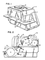
- a printer 10 is designed as a two station, receipt/slip and journal printer.
- the receipt/slip printing station occupies a front portion 12 and the journal printing station occupies a rearward portion 14 of the printer.
- a slip table 16 is provided along the left hand side of the printer 10.
- a front cover 17 swings toward the right to expose certain operating parts of the printer 10.
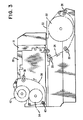
- Figs. 2 and 3 are right and left side elevational views and show certain elements of the printer 10 in diagrammatic form.
- the receipt/slip portion 12 and the journal portion 14 include individual print wire solenoids (not shown) along with a ribbon cassette 18 for the receipt/slip printing operation and a ribbon cassette 20 for the journal printing operation.
- a roll 22 of receipt paper is journaled at the front of the printer 10 and the receipt paper 24 is driven and guided by appropriate pairs of rollers, as 26, 28, 30 and 32 in a path past the receipt/slip printing station for printing operation and for issuance of a receipt 33 after cutting thereof from the receipt paper 24.
- a supply roll 34 of journal paper is positioned in a cradle at the rear of the printer 10 and the journal paper 36 is driven and guided by appropriate pairs of rollers, as 38 and 40, in a path from the supply roll 34, past the journal printing station, and onto a take-up roll 42.
- a timing plate 43 (Fig. 2) is provided at the receipt/slip printing station for positioning the receipt/slip feed rolls.
- Fig. 4 is an elevational view and Fig. 5 is a perspective view of the receipt cutting mechanism according to a preferred embodiment of the present invention.
- a first check in such operation is made as to whether or not the carriage for the cutting knife or blade is at the home position. If the carriage is not at the home position, the control mechanism or other means moves the carriage to such home position. After a printing operation is completed, the carriage is moved or driven to the cutting position to cut a receipt from the receipt paper. The cutting operation may be one of partial cut or full cut dependent upon the desires or requirements of the business. At the completion of the cutting operation, the carriage is returned to the home position.
- a right side plate 44 and a left side plate 46 provide support for the receipt cutting mechanism.
- the right side and the left side notations are provided for description of the arrangements illustrated in Figs. 4 and 5.
- a pair of shafts 48 and 50 are secured to the side plates 44 and 46 and provide support for a carriage 52 that is slidably moved along the shafts 48 and 50 in transverse direction on the printer 10.
- the carriage 52 is driven in such transverse direction by means of a reversing-type motor 54 which is suitably supported by the left side plate 46.
- a toothed belt 56 is trained around a pulley 58 on the end of a motor shaft 60 and around a pulley 62 on the end of a lead screw-type drive shaft 64.
- the drive shaft 64 is coupled by means of a threaded hub 65 associated with the carriage 52 for driving thereof across the printer 10.
- a knob 66 is secured to the end of the shaft 64 to be used for turning the shaft in case of a jam or for manually moving the carriage 52 to a desired position.
- a belt or like resilient member 68 (Fig. 5) with teeth 70 is stretched across the printer parallel to the shafts 48 and 50 and is secured to the side plates 44 and 46 by suitable means.
- a bracket 72 provides support for drive mechanism associated with the lead screw drive shaft 64 for driving the carriage 52 across the printer 10.
- a circular cutting knife or blade 74 is rotatably carried by the bracket 72 of the carriage 52 and is operably associated with a knife edge 75 of a fixed blade 76.
- the fixed blade 76 is suitably secured to structure between the side plates 44 and 46 of the printer 10. Rotation of the cutting blade 74 along the knife edge 75 of the fixed blade 76 operates to cut a receipt 33 from the receipt paper 24 (Fig. 5).
- a light reflecting type photosensor 80 is positioned above and secured to the top of the carriage 52 and is operably associated with a first light reflective plate 82 positioned in the home position of the carriage 52 and is operably associated with a second light reflective plate 84 positioned in the cutting position of the carriage 52.
- the photosensor 80 includes a light emitting element (not shown) facing the reflective plates 82 and 84.
- the plate 82 has a reflecting face or surface 86 (Fig. 4) opposed to the photosensor 80 and the plate 84 has a reflecting face or surface 88 also opposed to the photosensor 80.
- Figs. 6A, 6B and 6C show the relationship between the positions of the reflective plates 82 and 84 and the magnitudes of the output voltages of the photosensor 80.
- the reflective plate 82 is positioned at a distance d1 of four millimeters from the face of the photosensor 80 and the reflective plate 84 is positioned at a distance d2 of two millimeters from the face of the photosensor 80. Since the photosensor 80 is mounted on the carriage 52 and moves therewith across the printer 10, the photosensor 80 scans the reflecting surface 86 (Fig. 4) of the plate 82 and scans the reflecting surface 88 (Fig. 4) of the plate 84. As seen in Fig.
- the first light reflective plate 82 includes an edge 81 with the home position of the carriage 52 being represented in the area to the left of the edge 81 or location L1.
- the second light reflective plate 84 includes one edge 83 thereof representing the location of a partial cut position or location L2 and another edge 85 thereof representing the location of a full cut position or location L3 of the carriage 52 and the cutting blade 74.
- the cutting operation for partial cut of the receipt paper 24 takes place from edge 81 of reflective plate 82 to edge 83 of reflective plate 84.
- the cutting operation for full cut of the receipt paper 24 takes place from edge 81 of reflective plate 82 to edge 85 of reflective plate 84.
- the edges 81, 83 and 85 provide photosensor read locations for output voltages.
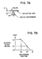
- Figs. 7A and 78 show the relationship between the photosensor 80 and the magnitude of the output voltages in the two positions of the photosensor 80.
- the voltage signal detected by the photosensor 80 is proportional to the amount of light received by the light receiving element of the photosensor 80 after reflection of the light emitted by the light emitting element of the photosensor 80 off the surface of the respective reflective plate 82 or 84.
- the photosensor 80 detects the reflective output voltage V1 in the home position of the carriage 52 and the reflective output voltage V2 in the cutting position, as shown in Fig. 7B, wherein output voltage V1 is indicated as being less than output voltage V2.
- FIG. 7A illustrates a variable distance d between a photosensor 80 and a reflecting plate (82 or 84) and Fig. 7B shows a variation in the relative output voltage (V2 greater than V1) in accordance with the change in the distance d at the respective locations when the photosensor 80 is moved horizontally across the printer 10.
- the higher output voltage V2 is generated by the greater amount of light reflected through the lesser distance d2 from the reflective plate 84 (Fig. 6A).
- a threshold voltage designated as V TH1 (Fig. 6B) is always lower than output voltage V1 and is higher than a voltage V0, the latter being the case wherein no reflection plate is in the path of the light emitted from the photosensor 80.
- a threshold voltage, designated as V TH2 (Fig. 6B) is always higher than output voltage V1 and is lower than output voltage V2. Accordingly, when the output voltage V OUT of the photosensor 80 is lower than threshold voltage V TH1 , the cutting blade 74 is in an intermediate position between the home position or location L1 and the cutting position or location L2 or L3.
- Fig. 6C shows the relationship between the photosensor 80 and the position of the cutting blade 74 wherein a high digital output V H is generated when the blade 74 is in the position of either one of the reflective plates 82 or 84. It is seen from Fig. 6A that the photosensor 80 receives a reflected signal from the face 86 of the reflective plate 82, and that the photosensor 80 does not receive a reflected signal, indicated at V L , from the time of passing edge 81 of the plate 82 until the photosensor 80 sees the edge 83 of the reflective plate 84.
- the photosensor 80 receives a reflected signal from the face 88 of the reflective plate 84 at the time of passing edge 83 thereof indicating a partial cut position of the cutting blade 74 on the carriage 52 and at the time of passing edge 85 of the reflective plate 84 indicating a full cut position.
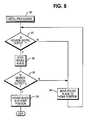
- Fig. 8 shows the initial processing steps, as started at block 90, when the printer 10 is turned on for printing operation.
- the digital output of the photosensor 80 is "0" or low level
- the cutting blade 74 is not in the home position, so the process makes a decision as to the logic level and goes through the steps of block 92 and of block 94 to move the cutting blade to the home position.
- the digital output of the sensor 80 is "1" or high level
- the process makes a decision and goes through step 92 and the motion of the cutting blade 74 is stopped (block 96).
- the level of the output voltage V OUT (Fig. 6B) of the photosensor 80 (hereafter sensor analog output) is determined and the process makes a decision regarding such sensor analog output (block 9B). If the sensor analog output (V OUT ) is of the value of V1 in the home position, the cutting blade 74 is not moved as the blade 74 is indicated as already being in the home position (block 100). If the sensor analog output (V OUT ) is of the value of V2 in the cutting position, the cutting blade 74 is moved to the home position (block 94).
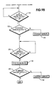
- Figs. 9A and 9B show the steps of a full cut processing, as started at block 102, and wherein the cutting blade 74 is moved from home position L1 to the read end position, as indicated at location L3 in Fig. 6A.
- the operation is that of moving the cutting blade 74 from the home position to the cutting position (block 104) to fully cut the receipt paper 24 (Fig. 5).
- the sensor digital output changes in the order of "1" to "0" to "1".
- the process is checked to see whether or not the sensor analog output is V2 (block 108). If the sensor analog output is not V2, the operation is in error and the movement of the cutting blade 74 is stopped to correct the error in operation (blocks 110 and 112). If the sensor analog output is V2, the process continues to block 114. When the sensor digital output changes from "1" to "0” (block 114), the cutting blade 74 is stopped (block 116) indicating that the receipt paper 24 is fully cut. The cutting blade 74 is then returned to the home position (block 118).
- the changing of the sensor digital output from "0" to "1" indicates that the cutting blade 74 is in the L3 location or full cut position (Fig. 6A).
- the process of cutting blade 74 movement is then checked to see whether or not the sensor analog output is V2 (block 122). If the sensor analog output is not V2, the operation is in error and is stopped to correct the error (block 130). If the sensor analog output is V2, the process continues to block 124. When the sensor digital output changes from "1" to "0", the cutting blade 74 is in the L2 location or partial cut position (Fig. 6A).
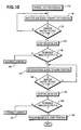
- Fig. 10 shows the steps of a partial cut processing, as started at block 134, and wherein the cutting blade 74 is moved from home position L1 to read end position, indicated at location L2, for the partial cutting operation.
- the cutting blade 74 is returned to the home position.
- the movement of the cutting blade 74 is started (block 136) toward the partial cut position.
- the sensor digital output changes from "0" to "1” (block 138)
- the movement of the cutting blade 74 is stopped (block 140) and the process is checked to see whether or not the sensor analog output is V2 (block 142). If the sensor analog output is V2, the blade 74 is returned to the home position (block 144).
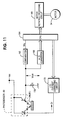
- Fig. 11 shows an arrangement of the control circuit for the drive mechanism for the cutting blade 74.
- the reflex type photosensor 80 is carried on the carriage 52 for the cutting blade 74.
- the photosensor 80 generates a sensor analog output V OUT in accordance with a difference in the amount of reflected light from the surface or face 86 of reflective plate 82 or from the surface or face 88 of reflective plate 84.
- the sensor analog output V OUT is sent to an analog-to-digital converter 160 which determines whether such output is of the magnitude V1 or V2.
- the output V OUT from the photosensor 80 is also sent to a comparator 162.
- the output of comparator 162 is used as an interruption signal, designated as V HL , to a central processing unit (CPU) 164 which includes the programs of the steps of operation shown in Figs. 8, 9A, 9B and 10.
- the signal V HL is shown as being and can be either a low output voltage V L or a high output voltage V H , as indicated in Fig. 6C.
- a motor rotating/reversing circuit 166 is controlled by the central processing unit 164 for operating the motor 54.
- a light emitting diode current correcting circuit 170 is connected to the CPU 164 and to the photosensor 80 which detects signals from reflecting face 86 or 88.
- a resistor 172 is connected to the output of the photosensor 80 and to ground.
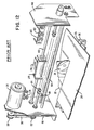
- Fig. 12 shows an arrangement of a cutting mechanism in a conventional printer which used some of the same parts as described above.
- the motor 54 drives a carriage 174 by means of the belt 56 and the lead screw 64.
- the cutting blade 74 is carried by the carriage 174 and cooperates with the fixed blade 76 for cutting the receipt paper 24 and providing a receipt 33.
- the carriage 174 has a light shielding plate 176 attached thereto which is operable with a plurality of light transmission type photosensors 178, 180 and 182.
- the light transmission type photosensors 178, 180 and 182 each include a light emitting element and a light receiving element which is positioned in facing relationship with the light emitting element.
- the photosensors 178, 180 and 182 are located in the home position and in the paper cutting position, the latter position being disposed at the end of the paper cutting operation.
- the light shielding plate 176 is provided on the carriage 174 for shielding the light of the respective photosensor 178, 180 or 182.
- the position of the carriage 174 is sensed in the manner of presence or absence of an output from the respective photosensor 178, 180 or 182 for controlling the movement of the cutting blade 74.
- the photosensor 178 is located at the home position, the photosensor 180 is located at the partial cut position and the photosensor 182 is located at the full cut position of the cutting mechanism. It is thus seen that at least two photosensors, 178 and 180 or 178 and 182, are required to provide a cutting operation for either a partial cut or a full cut of the receipt paper 33. If both a partial cut and a full cut are desired, the operation requires all three photosensors 178, 180 and 182. In this regard and using the cutting mechanism in a conventional printer, the number of components is increased and the manufacturing and assembling steps are complicated so that a reduction in cost cannot be attained.
- the photosensor 80 on the carriage 52 receives a lower level or lesser amount of light from the reflective plate 82 by reason of the longer distance d1 from the photosensor 80 to the face of the reflective plate 82.
- the control apparatus and circuitry recognizes that the cutting blade 74 is currently in the home position by reason of the lesser light-lower output voltage signal.
- the photosensor 80 receives a higher level or greater amount of light from the reflective plate 84 due to the shorter distance from the photosensor 80 to the face of the reflective plate 84.
- the control apparatus and circuitry recognize that the cutting blade 74 is currently in the cutting position by reason of the greater light-higher output voltage signal. The result of this arrangement is that the operation of the cutting blade 74 is controlled by the single photosensor 80.
- the present invention provides the single light reflecting photosensor 80 secured on the carriage 52 of the cutting blade 74.
- the light reflecting plates 82 and 84 are located in home and cutting positions and are at different distances from the photosensor 80 to enable sensing of the current position of the cutting blade 74 by a single photosensor for accurately controlling the movement and operation of the cutting blade.
- the number of components can be reduced, the assembling operation can be facilitated and the manufacturing cost can be reduced.
- a compact dot matrix printer that includes control apparatus for a receipt cutting mechanism, wherein the cutting blade is caused to be rotated by the external driving force that is used to move the cutting blade carriage across the printer.
- the control apparatus includes a single photosensor element operating with one reflective plate at one distance therefrom for indicating the home position of the cutting blade and operating with another reflective plate at a different distance from the photosensor for indicating the cutting position of the cutting blade.
Landscapes
- Handling Of Sheets (AREA)
Applications Claiming Priority (2)
| Application Number | Priority Date | Filing Date | Title |
|---|---|---|---|
| JP63230162A JPH0292660A (ja) | 1988-09-16 | 1988-09-16 | プリンタ装置におけるペーパ切断制御装置 |
| JP230162/88 | 1988-09-16 |
Publications (3)
| Publication Number | Publication Date |
|---|---|
| EP0359583A2 true EP0359583A2 (fr) | 1990-03-21 |
| EP0359583A3 EP0359583A3 (fr) | 1991-01-30 |
| EP0359583B1 EP0359583B1 (fr) | 1993-12-08 |
Family
ID=16903571
Family Applications (1)
| Application Number | Title | Priority Date | Filing Date |
|---|---|---|---|
| EP89309402A Expired - Lifetime EP0359583B1 (fr) | 1988-09-16 | 1989-09-15 | Système de commande pour imprimante |
Country Status (4)
| Country | Link |
|---|---|
| US (1) | US4981059A (fr) |
| EP (1) | EP0359583B1 (fr) |
| JP (1) | JPH0292660A (fr) |
| DE (1) | DE68911246T2 (fr) |
Cited By (1)
| Publication number | Priority date | Publication date | Assignee | Title |
|---|---|---|---|---|
| EP1044819A3 (fr) * | 1999-04-14 | 2001-06-27 | Star Micronics Co., Ltd. | Appareil de coupe et imprimante |
Families Citing this family (30)
| Publication number | Priority date | Publication date | Assignee | Title |
|---|---|---|---|---|
| DE8908720U1 (de) * | 1989-07-18 | 1989-09-07 | Carl Schmale GmbH & Co KG, 4434 Ochtrup | Querschneidevorrichtung für bahnförmiges Gut, insbesondere Textilbahnen |
| JP2542437B2 (ja) * | 1989-08-31 | 1996-10-09 | 株式会社テック | プリンタ |
| US5134917A (en) * | 1991-04-11 | 1992-08-04 | David Holland | Apparatus and method for making V-groove insulation and tank wrap |
| DE59207629D1 (de) * | 1992-09-14 | 1997-01-16 | Siemens Nixdorf Inf Syst | Verfahren zum Verstellen einer Steuerscheibe |
| JP2718612B2 (ja) * | 1993-01-12 | 1998-02-25 | 日東電工株式会社 | 印字装置 |
| US5611253A (en) * | 1993-09-07 | 1997-03-18 | Tohoku Ricoh Co., Ltd. | Cutting device |
| US5415484A (en) * | 1994-02-28 | 1995-05-16 | Pitney Bowes Inc. | Method and apparatus for cutting mailing machine roll tape |
| US5816720A (en) * | 1994-03-15 | 1998-10-06 | Interbold | Printer mechanism for automated teller machine |
| US5464289A (en) * | 1994-08-24 | 1995-11-07 | Beaudry; Wallace J. | Electrographic label printing system |
| WO1998036881A1 (fr) * | 1997-02-20 | 1998-08-27 | Matsushita Electric Industrial Co., Ltd. | Dispositif d'impression a coupeuse |
| US5911530A (en) * | 1997-09-02 | 1999-06-15 | Hewlett-Packard Company | Wheel-driven rotary cutter for printer |
| JP3839141B2 (ja) * | 1997-09-03 | 2006-11-01 | 富士写真フイルム株式会社 | プリンタのカッター装置 |
| DE59809645D1 (de) * | 1998-02-11 | 2003-10-23 | Imip Llc Wilmington | Schneidvorrichtung für eine Materialbahn |
| US6315474B1 (en) * | 1998-10-30 | 2001-11-13 | Hewlett-Packard Company | Automatic paper cutter for large format printer |
| US6889585B1 (en) * | 2000-01-04 | 2005-05-10 | International Business Machines Corporation | Cutter blade position detection mechanism and method of reporting cutter malfunction |
| JP3735014B2 (ja) * | 2000-07-17 | 2006-01-11 | アルプス電気株式会社 | 用紙切断機構及びこの用紙切断機構を有するプリンタ |
| US8690463B2 (en) * | 2004-11-12 | 2014-04-08 | Toshiba Gloabl Commerce Solutions Holdings Corporation | Receipt printer configurable for full or partial cut |
| JP2009066961A (ja) * | 2007-09-14 | 2009-04-02 | Alps Electric Co Ltd | プリンタ |
| JP2009179036A (ja) * | 2008-02-01 | 2009-08-13 | Seiko Epson Corp | カッター装置、記録装置 |
| JP5123707B2 (ja) * | 2008-03-28 | 2013-01-23 | 富士通フロンテック株式会社 | プリンタ装置および搭乗券のカット位置制御方法 |
| US8950957B2 (en) | 2012-03-14 | 2015-02-10 | Transact Technologies Incorporated | Configurable printer for different paper sizes and methods for configuring a printer for different paper sizes |
| US8960064B2 (en) | 2012-03-14 | 2015-02-24 | Transact Technologies Incorporated | Configurable cutter mechanism for a printer and method for configuring a cutter mechanism for a printer |
| US9315054B2 (en) | 2013-09-27 | 2016-04-19 | Transact Technologies Incorporated | Self-adjusting paper bucket for a printer and methods for providing a self-adjusting paper bucket |
| CN105291169B (zh) * | 2015-10-15 | 2017-04-12 | 杭州爱科科技有限公司 | 一种抗伸缩差横梁机构 |
| CN108472822B (zh) | 2015-12-07 | 2020-04-03 | 艾利丹尼森零售信息服务公司 | 用于打印系统的切割机附件 |
| CN110709218B (zh) | 2017-05-01 | 2021-08-31 | 艾利丹尼森零售信息服务公司 | 独立切割装置 |
| NL2019851B1 (en) * | 2017-11-03 | 2019-05-13 | Vmi Holland Bv | Apparatus and method for converting a sheet into a continuous strip |
| US10974925B2 (en) | 2018-12-14 | 2021-04-13 | Transact Technologies Incorporated | Spindle assembly for a printer for accommodating paper rolls of different sizes |
| US10960565B2 (en) | 2019-03-06 | 2021-03-30 | Transact Technologies Incorporated | Cutter mechanism for a printer and methods of cutting paper media in a printer |
| JP7547051B2 (ja) * | 2020-01-30 | 2024-09-09 | キヤノン株式会社 | 画像記録装置、画像記録装置の制御方法、及びプログラム |
Family Cites Families (9)
| Publication number | Priority date | Publication date | Assignee | Title |
|---|---|---|---|---|
| US3805652A (en) * | 1972-05-03 | 1974-04-23 | Ind Res & Eng Inc | Automatic tail cutter |
| DE2655832C2 (de) * | 1976-12-07 | 1983-12-15 | Mannesmann AG, 4000 Düsseldorf | Trennvorrichtung zum Abtrennen von Papierbahnen in einem Drucker |
| IT1135600B (it) * | 1981-02-24 | 1986-08-27 | Honeywell Inf Systems | Stampante seriale munita di taglierina |
| US4604632A (en) * | 1982-08-16 | 1986-08-05 | Canon Kabushiki Kaisha | Recorder transport for perforating and cutting operations |
| US4516493A (en) * | 1983-02-10 | 1985-05-14 | Harold Schemenauer | Apparatus for imprinting and cutting a tape or ribbon |
| DE3430443A1 (de) * | 1984-08-18 | 1986-02-20 | Ibm Deutschland Gmbh, 7000 Stuttgart | Schneidvorrichtung fuer papier- und folienbahnen, insbesondere fuer druckwerke, plotter, kopiergeraete und aehnliche maschinen |
| US4693151A (en) * | 1985-01-09 | 1987-09-15 | Monarch Marking Systems, Inc. | Cutting method and apparatus for stacker |
| DE3510995A1 (de) * | 1985-03-27 | 1986-10-09 | Mannesmann Kienzle GmbH, 7730 Villingen-Schwenningen | Schneideinrichtung fuer formularbahnen |
| US4779500A (en) * | 1986-09-19 | 1988-10-25 | Eastman Machine Company | Automatic end cutter |
-
1988
- 1988-09-16 JP JP63230162A patent/JPH0292660A/ja active Pending
-
1989
- 1989-07-24 US US07/384,198 patent/US4981059A/en not_active Expired - Fee Related
- 1989-09-15 EP EP89309402A patent/EP0359583B1/fr not_active Expired - Lifetime
- 1989-09-15 DE DE68911246T patent/DE68911246T2/de not_active Expired - Fee Related
Cited By (2)
| Publication number | Priority date | Publication date | Assignee | Title |
|---|---|---|---|---|
| EP1044819A3 (fr) * | 1999-04-14 | 2001-06-27 | Star Micronics Co., Ltd. | Appareil de coupe et imprimante |
| US6302605B1 (en) | 1999-04-14 | 2001-10-16 | Star Micronics Co., Ltd. | Rotary cutter apparatus for printer with full and partial cutting modes |
Also Published As
| Publication number | Publication date |
|---|---|
| JPH0292660A (ja) | 1990-04-03 |
| DE68911246D1 (de) | 1994-01-20 |
| DE68911246T2 (de) | 1994-06-16 |
| EP0359583A3 (fr) | 1991-01-30 |
| EP0359583B1 (fr) | 1993-12-08 |
| US4981059A (en) | 1991-01-01 |
Similar Documents
| Publication | Publication Date | Title |
|---|---|---|
| EP0359583B1 (fr) | Système de commande pour imprimante | |
| US4734868A (en) | Precision paper transport system | |
| US4652153A (en) | Wire dot-matrix printer | |
| US4655624A (en) | Ink ribbon cassette | |
| US4916638A (en) | Media advance system for swath printers | |
| US4892426A (en) | Paper movement monitor | |
| EP0138444B1 (fr) | Appareil pour imprimer des images | |
| US6169557B1 (en) | Recording apparatus | |
| EP1184189B1 (fr) | Appareil de transport des supports d'impression | |
| US5255987A (en) | Paper margin detecting device for use in printing apparatus | |
| EP0659572B1 (fr) | Imprimante et sa méthode de commande | |
| AU753299B2 (en) | Media sensor system for printer mechanism | |
| US10071575B2 (en) | Printers and methods for detecting print media thickness therein | |
| CA2053813C (fr) | Dispositif optique servant a decler la presence du papier et methode connexe | |
| US5214271A (en) | Method of determining detector lifetime using a stepped resistor network | |
| JP2924021B2 (ja) | プラテンギャップ調整装置 | |
| JPS60171183A (ja) | プリンタ装置 | |
| WO1989001145A1 (fr) | Detecteur optique reglable de bord de ruban | |
| JP2699923B2 (ja) | プリンタ装置 | |
| JPH0811365A (ja) | ヘッドギャップ調整機構 | |
| JP2546372B2 (ja) | シリアルプリンタ | |
| JPH05238099A (ja) | プリンタ | |
| JPH01238978A (ja) | ヘッドギャップ自動調整方式 | |
| JPH0336072A (ja) | 記録装置 | |
| JPH03187779A (ja) | プリンタ |
Legal Events
| Date | Code | Title | Description |
|---|---|---|---|
| PUAI | Public reference made under article 153(3) epc to a published international application that has entered the european phase |
Free format text: ORIGINAL CODE: 0009012 |
|
| AK | Designated contracting states |
Kind code of ref document: A2 Designated state(s): DE FR GB |
|
| PUAL | Search report despatched |
Free format text: ORIGINAL CODE: 0009013 |
|
| AK | Designated contracting states |
Kind code of ref document: A3 Designated state(s): DE FR GB |
|
| 17P | Request for examination filed |
Effective date: 19910713 |
|
| 17Q | First examination report despatched |
Effective date: 19930331 |
|
| RAP1 | Party data changed (applicant data changed or rights of an application transferred) |
Owner name: NCR INTERNATIONAL INC. |
|
| GRAA | (expected) grant |
Free format text: ORIGINAL CODE: 0009210 |
|
| AK | Designated contracting states |
Kind code of ref document: B1 Designated state(s): DE FR GB |
|
| REF | Corresponds to: |
Ref document number: 68911246 Country of ref document: DE Date of ref document: 19940120 |
|
| ET | Fr: translation filed | ||
| PLBE | No opposition filed within time limit |
Free format text: ORIGINAL CODE: 0009261 |
|
| STAA | Information on the status of an ep patent application or granted ep patent |
Free format text: STATUS: NO OPPOSITION FILED WITHIN TIME LIMIT |
|
| 26N | No opposition filed | ||
| REG | Reference to a national code |
Ref country code: GB Ref legal event code: IF02 |
|
| PGFP | Annual fee paid to national office [announced via postgrant information from national office to epo] |
Ref country code: GB Payment date: 20020701 Year of fee payment: 14 |
|
| PGFP | Annual fee paid to national office [announced via postgrant information from national office to epo] |
Ref country code: FR Payment date: 20020716 Year of fee payment: 14 |
|
| PGFP | Annual fee paid to national office [announced via postgrant information from national office to epo] |
Ref country code: DE Payment date: 20030226 Year of fee payment: 14 |
|
| PG25 | Lapsed in a contracting state [announced via postgrant information from national office to epo] |
Ref country code: GB Free format text: LAPSE BECAUSE OF NON-PAYMENT OF DUE FEES Effective date: 20030915 |
|
| PG25 | Lapsed in a contracting state [announced via postgrant information from national office to epo] |
Ref country code: DE Free format text: LAPSE BECAUSE OF NON-PAYMENT OF DUE FEES Effective date: 20040401 |
|
| GBPC | Gb: european patent ceased through non-payment of renewal fee |
Effective date: 20030915 |
|
| PG25 | Lapsed in a contracting state [announced via postgrant information from national office to epo] |
Ref country code: FR Free format text: LAPSE BECAUSE OF NON-PAYMENT OF DUE FEES Effective date: 20040528 |
|
| REG | Reference to a national code |
Ref country code: FR Ref legal event code: ST |