EP0359214B1 - Cassette à bande à détection optique de la fin de la bande - Google Patents
Cassette à bande à détection optique de la fin de la bande Download PDFInfo
- Publication number
- EP0359214B1 EP0359214B1 EP89116898A EP89116898A EP0359214B1 EP 0359214 B1 EP0359214 B1 EP 0359214B1 EP 89116898 A EP89116898 A EP 89116898A EP 89116898 A EP89116898 A EP 89116898A EP 0359214 B1 EP0359214 B1 EP 0359214B1
- Authority
- EP
- European Patent Office
- Prior art keywords
- light
- tape
- cassette
- cassette half
- light receiving
- Prior art date
- Legal status (The legal status is an assumption and is not a legal conclusion. Google has not performed a legal analysis and makes no representation as to the accuracy of the status listed.)
- Expired - Lifetime
Links
- 238000003780 insertion Methods 0.000 claims description 12
- 230000037431 insertion Effects 0.000 claims description 12
- 239000000463 material Substances 0.000 claims description 8
- 230000003287 optical effect Effects 0.000 claims description 4
- 238000001514 detection method Methods 0.000 claims description 2
- 238000005192 partition Methods 0.000 description 12
- 239000003086 colorant Substances 0.000 description 6
- 238000000034 method Methods 0.000 description 5
- 230000007257 malfunction Effects 0.000 description 3
- 238000010586 diagram Methods 0.000 description 2
- 239000007767 bonding agent Substances 0.000 description 1
- 230000007547 defect Effects 0.000 description 1
- 239000000428 dust Substances 0.000 description 1
- 238000002474 experimental method Methods 0.000 description 1
- 238000005286 illumination Methods 0.000 description 1
- 230000031700 light absorption Effects 0.000 description 1
- 238000004519 manufacturing process Methods 0.000 description 1
- 238000012986 modification Methods 0.000 description 1
- 230000004048 modification Effects 0.000 description 1
- 239000003973 paint Substances 0.000 description 1
- 229920005990 polystyrene resin Polymers 0.000 description 1
- 229920005989 resin Polymers 0.000 description 1
- 239000011347 resin Substances 0.000 description 1
Images


Classifications
-
- G—PHYSICS
- G11—INFORMATION STORAGE
- G11B—INFORMATION STORAGE BASED ON RELATIVE MOVEMENT BETWEEN RECORD CARRIER AND TRANSDUCER
- G11B23/00—Record carriers not specific to the method of recording or reproducing; Accessories, e.g. containers, specially adapted for co-operation with the recording or reproducing apparatus ; Intermediate mediums; Apparatus or processes specially adapted for their manufacture
- G11B23/02—Containers; Storing means both adapted to cooperate with the recording or reproducing means
- G11B23/04—Magazines; Cassettes for webs or filaments
- G11B23/08—Magazines; Cassettes for webs or filaments for housing webs or filaments having two distinct ends
- G11B23/087—Magazines; Cassettes for webs or filaments for housing webs or filaments having two distinct ends using two different reels or cores
- G11B23/08707—Details
- G11B23/08714—Auxiliary features
-
- G—PHYSICS
- G11—INFORMATION STORAGE
- G11B—INFORMATION STORAGE BASED ON RELATIVE MOVEMENT BETWEEN RECORD CARRIER AND TRANSDUCER
- G11B23/00—Record carriers not specific to the method of recording or reproducing; Accessories, e.g. containers, specially adapted for co-operation with the recording or reproducing apparatus ; Intermediate mediums; Apparatus or processes specially adapted for their manufacture
- G11B23/02—Containers; Storing means both adapted to cooperate with the recording or reproducing means
- G11B23/04—Magazines; Cassettes for webs or filaments
- G11B23/08—Magazines; Cassettes for webs or filaments for housing webs or filaments having two distinct ends
- G11B23/087—Magazines; Cassettes for webs or filaments for housing webs or filaments having two distinct ends using two different reels or cores
- G11B23/08707—Details
- G11B23/08785—Envelopes
Definitions
- the present invention relates generally to tape cassettes and, more particularly, is directed to a tape cassette suitable as a so-called color tape cassette of a video tape recorder (VTR).
- VTR video tape recorder
- a tape cassette having wound therein a magnetic tape is useful in order to simplify the loading or unloading of a recording and reproducing magnetic tape in a video tape recorder. It is convenient for a user when this tape cassette is loaded into the video tape recorder, if the video tape recorder can automatically determine whether the magnetic tape within the tape cassette is in the rewound state (start mode) or whether the magnetic tape is in the wound state (end mode). For this reason, the tape cassette is generally provided with a mechanism, by which the start mode or the end mode of the magnetic tape can be detected from the outside of the cassette.
- Fig. 1 shows such a prior-art tape cassette which is generally designated by reference numeral 1.
- reference numeral 2 denotes an upper cassette half, 3 a lower cassette half and 4 a magnetic tape.
- a transparent leader/trailer tape 4a is connected to the respective ends of the magnetic tape 4.
- a guard panel 5 protects the magnetic tape 4 from dust, smudges, finger marks and so on.
- Transparent windows 6A, 6B are formed on the upper cassette half 2 so that the inside of the tape cassette 1 can be visually confirmed.
- Fig. 2 shows the lower cassette half 3 of the prior-art tape cassette of the example shown in Fig. 1.
- the magnetic tape 4 is supplied from a supply reel 7A and is taken up by a take-up reel 7B after having passed over a guide pole 11, a tape guide 12, a front panel 3b of the lower cassette half 3, a tape guide 13 and a guide roller 14.
- the supply reel 7A is held between a reel flange portion 8A and a lower reel flange (not shown), and the take-up reel 7B is held between a reel flange 8B and a lower reel flange (not shown).
- Brake levers 9A and 9B are respectively engaged with lower reel flanges (not shown), and these brake levers 9A and 9B are operated by a release mechanism 10 from the outside.
- arcuate front ribs 15 and 16 are formed to be substantially coaxial with the supply reel 7A and the take-up reel 7B, whereby a space 17 is formed between the magnetic tape 4 and the front rib 15. Also, a space 18 is formed on the front panel 3b. Loading posts (not shown) of a video tape recorder are inserted into these spaces 17 and 18 when the tape cassette 1 is loaded into the video tape recorder.
- a cylindrical wall 19 is formed in a portion where the front ribs 15 and 16 intersect. Through the cylindrical wall 19, there are provided lighting windows 19a and 19b in an opposing relation with an angular extent of substantially 180 degrees.
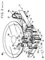
- a side wall 3a of the lower cassette half 3 near the side of the take-up reel 7B is recessed to form a partition 20 as shown in fig. 3.
- the partition 20 is covered with the guard panel 5.
- apertures 20a, 20b and a light receiving window 21 are formed through the partition 20.
- Two partitions 22, 23 extend from the lower cassette half 3 perpendicular to the partition 20 and aligned slits 22a, 23a are respectively formed on the partitions 22, 23.
- Rotating shafts 24c and 24d of a lid locking member 24 are engaged with the above-mentioned slits 22a and 23a, and the lid locking member 24 is generally spring-biased by a spring (not shown) in the direction shown by ⁇ in Fig. 3.
- a lock-releasing pin 24a and a lock lever 24b of the lid locking member 24 are projected to the outside through the apertures 20a and 20b of the partition 20, and the lock lever 24b is engaged with a lock slit 5a of the guard panel 5 (when the guard panel 5 is in its normally closed position).
- the engagement between the lock lever 24b and the lock slit 5a has to be released by inwardly pushing the lock-releasing pin 24a.
- a side wall 3c of the lower cassette half 3 is parallel to the side wall 3a. Further, one end of the side wall 3c at its position near the side of the supply reel 7A is concave to provide a partition 25 covered with the guard panel 5 as shown in Fig. 4. As shown in Fig. 4, a light receiving window 26 of a slit configuration is formed in the partition 25.
- a light emitting element 27 is inserted into the cylindrical wall 19 of the lower cassette half 3 and a start sensor 28 and an end sensor 29, each formed of a light receiving element, are located outside the light receiving windows 21 and 26.
- the start sensor 28 When the transparent leader tape 4a intersects an optical axis L1 connecting the lighting window 19a and the light receiving window 21, the start sensor 28 generates a signal, while when the transparent trailer tape 4a intersects an optical axis L2 connecting the lighting window 19b and the light receiving window 26, the end sensor 29 generates a signal.
- the video tape recorder can determine whether the magnetic tape 4 is in the start mode or in the end mode.
- the upper cassette half 2 and the lower cassette half 3 are both made of a black (light absorption property) resin so that the light emitted from the light emitting element 27 of the tape cassette 1, which is inserted into the video tape recorder is hardly reflected irregularly within the housing of the tape cassette 1. Also, lights from various light sources located outside the tape cassette 1 cannot pass through the upper cassette half 2 into the inside of the tape cassette 1 to be reflected on its inside wall and leaked to the outside through the light receiving windows 21, 26. Consequently, the start sensor 28 and the end sensor 29 are prevented from malfunctioning.
- a video tape recorder cassette be formed as a so-called color tape cassette.
- the applicants have made experiments wherein colors of the upper cassette half 2 and the lower cassette half 3 are changed to colors other than black, for example, gray and green.
- the experimental results revealed that, as shown in Fig. 3, an irregularly-reflected light L3 from the bottom plate 3d of the lower cassette half 3, an irregularly-reflected light L4 from the reel flange 8B, an external illumination light L5 passing through the upper cassette half 2 and so on enter the second sensor 28 through the light receiving window 21.
- the start sensor 28 is caused to malfunction when the magnetic tape 4 is not in the start mode.
- the end sensor 29 suffers from a similar problem.
- Japanese Laid-open Utility Model No. 62-57983 discloses a tape cassette in which, while the color thereof remains black, a cylindrical light-shielding member is provided near the light receiving window 21 in association with the lid locking member 24 (see Fig. 2) so as to improve the operation of the start sensor 28.
- GB-A- 2 119 751 discloses a tape cassette comprising an upper cassette half, and a lower cassete half, each having side walls, a light emitting element insertion portion located therebetween.
- a tape-shaped medium having a light transmissive portion wound between the upper and the lower cassette halves and surrounding the light emitting element insertion portion, a light receiving window through a side wall of one of the upper cassette half or the lower cassette half so as to oppose the light emitting element insertion portion across the tape-shaped medium, whereby when the tape cassette is loaded into a recording and reproducing apparatus, a light emitting element can be inserted into the light emitting element insertion portion and a light receiving element can be located outside of the light receiving window, to thereby establish a light path therebetween and allow detection of the predetermined portion of the tape-shaped medium, arcuate light shielding ribs substantially coaxial with the supply reel and the take-up reel and formed on at least one of the upper cassette half or the lower cassette half so as to face each other and to form opening
- an object of the present invention to provide a tape cassette in which an upper cassette half or a lower cassette half can be made of a material whose color is other than black without causing a light receiving element to malfunction.
- a tape cassette according to the present invention is characterized in that the light shielding ribs of the light shielding member are integrally formed with at least one of the upper or lower cassette half, and surround the light path except at one side of the light shielding member at which the lid locking member is placed.
- Figs. 5 to 10 like parts corresponding to those of Figs. 1 to 4 are marked with the same references and therefore will not be described in detail.
- the upper cassette half 2 and the lower cassette half 3 are colored to have light reflection properties for colors other than black.
- Fig. 5 shows the lower cassette half 3 of an embodiment of the tape cassette 1 according to the present invention.
- the brake levers 9A, 9B are spring-biased by a single spring 9C in the direction of the release mechanism 10.
- a tape pad 31 is inserted into a slit forming portion 30 near the tape guide 12, whereby the magnetic tape 4 is sandwiched between the tape pad 31 and the guide pole 11.
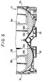
- Black sheets 15A and 16A are respectively bonded to the inner surfaces of the front ribs 15 and 16 formed on the lower cassette half 3.
- black sheets 32A and 33A are respectively bonded to the inner surfaces of front ribs 32 and 33 formed on the upper cassette half 2 according to this embodiment.
- black sheets 32B and 33B are bonded to the inside surface of a top plate 2d of the upper cassette half 2.
- ribs 34 and 35 extend from the bottom plate 3d of the lower cassette half 3 near the supply reel 7B side so that they are on opposite sides of the light path L1 extending from the lighting window 19a of the cylindrical wall 19 to the light receiving window 21.
- the light emitting element 27 is inserted into the cylindrical wall 19.
- the rib 35 is erected on the bottom plate 3d of the lower cassette half 3 so that it substantially perpendicularly abuts against the side wall 3a.
- the rib 35 becomes substantially arcuate along the periphery of the lower reel flange 8D.
- the most important feature of the rib 35 is that it extends to a portion 35a surrounded by a broken line in Fig. 7A. This extended portion 35a of the rib 35 can prevent the light emitted from the light emitting element 27 and irregularly reflected by the reel flange 8B, or the like, from reaching the light receiving window 21.
- reference numeral 36 designates a shaft which is implanted on the bottom plate 3d of the lower cassette half 3.
- a cylindrical portion 37c of a lid locking member 37 is rotatably engaged with the shaft 36, and a helical or coiled spring 38 is wound around the shaft 36 above the cylindrical portion 37c.
- One end of the coiled spring 38 is brought in contact with a spring stop 39 formed on the side wall 3a of the lower cassette half 3 while the other end thereof is brought in contact with a spring stop 37d of the lid locking member 37, whereby the lid locking member 37 is constantly spring-biased around the shaft 36 in the ⁇ direction.
- a lock-releasing pin 37a and a lock lever 37b of the lid locking member 37 are respectively projected through the apertures 20a and 20b formed through the partition 20 of the lower cassette half 3 to the outside thereof and maintained in that condition.
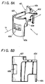
- a member 40 is sandwiched among the partition 20, having the light receiving window 21, and the ribs 34 and 35 in such a manner that it surrounds the light path L1.
- This member 40 will hereinafter be referred to as the tunnel core piece member and is molded of black polystyrene resin.
- One end portion 40a of the tunnel core piece member 40 is curved along the rib 35, and an opening portion 40b is formed through the curved end portion 40a of the tunnel core piece member 40 so as to surround the light path L1.
- Figs. 8A and 8B illustrate the above-mentioned tunnel core piece member 40 more in detail.
- the other end 40c of the tunnel core piece member 40 is extended to come in contact with the partition 22 of the lower cassette half 3 and that the tunnel core piece member 40 is concave to provide concave portions 40d and 40e so that it may not hinder the rotation of the lid locking member 37.
- the curved end portion 40a is increased in height to form an upper end 40f so that when the upper cassette half 2 is coupled to the lower cassette half 3, the upper end 40f abuts against the top plate 2d of the upper cassette half 2.
- results reveal that the presence of the black sheets 15A, 16A reduces the amount of light leaked to the light receiving window 21 by about 10% regardless of the colors of the upper cassette half 2 and the lower cassette half 3. Further, results also reveal that the presence of the black tunnel core piece member 40 reduces the amount of light leaked to the light receiving window 21 by about 80%.
- the amount of light leaked to the light receiving window 21 is very small when the colors of the upper cassette half 2 and the lower cassette half 3 are dark green, dark brown and gunmetal gray.
- the rib 34 and the extended rib 35 are erected on the lower cassette half 3 so as to be on opposite sides of the light path L1 and the black tunnel core piece member 40 is provided so as to surround the light path L1, it is possible to reduce the amount of stray light leaked to the light receiving window 21.
- black sheets 15A, 16A are bonded to the front ribs 15, 16 in this embodiment, it is possible to further reduce the amount of stray light leaked to the light receiving window 21.
- the tunnel core piece member 40 of this embodiment is provided with the concave portions 40d and 40e, by which the rotation of the lid locking member 37 used in this embodiment is not hindered. Furthermore, since the tunnel core piece member 40 is fixed only by assembling the upper cassette half 2 on the lower cassette half 3 after the tunnel core piece member 40 is inserted into the lower cassette half 3, the assembly-process of the tape cassette 1 of this embodiment can be greatly simplified. In this case, the tunnel core piece member 40 might be bonded to the bottom plate 3d of the lower cassette half 3 by a bonding agent.
- the tunnel core piece member 40 can be replaced with a tunnel core piece member 41 shown in Fig. 9.
- the tunnel core piece member 41 is comprised of a slit 41b surrounding the light path L1, a positioning reference corner portion 41a, an extended portion 41c and an abutting surface portion 41f.
- the tunnel core piece member 41 in the example shown in Fig. 9 is simple in arrangement and can be manufactured with ease.
- tunnel core piece members 40 and 41 may be replaced with a tunnel core piece member 42, the respective parts of which are formed as parts of the upper cassette half 2 and the lower cassette half 3 as shown in Fig. 10.
- reference numeral 43 designates a rib implanted on the top plate 2d of the upper cassette half 2 and 44 a rib implanted on the bottom plate 3d of the lower cassette half 3.
- abutting surfaces 43f and 44f are abutted against each other so that cut-away portions 43b and 44b are connected each other to form an opening portion through which the light path L1 passes.
- the inner surfaces of the ribs 43 and 44 might be coated with a black paint. It is obvious that if the tunnel core piece member 42 of the example shown in Fig. 10 is used, then it is possible to reduce the amount of light leaked to the light receiving window 21 similarly to the tunnel core piece member 40 of the example shown in Figs. 8A and 8B.
- the tunnel core piece members 40 and 41 are made of black material
- the present invention is not limited to the above black material and the tunnel core piece members 40 and 41 may be made of material whose color is, for example, the same as that of the upper cassette half 2 and the lower cassette half 3.
- the tunnel core piece members 40 and 41 are made of a material whose color is other than black, the thickness of each of the tunnel core piece members 40 and 41 should be increased.
- the color of the windows 6A and 6B (see Fig. 1) formed for visually confirming the inside of the tape cassette is selected to be gray or blue-based semitransparent or if the color of the reel flanges 8A and 8B is selected to be gray-based semitransparent, the amount of light leaked to the light receiving windows 21 and 26 will be reduced.
- the light-shielding ribs are formed on the upper cassette half or on the lower cassette half facing each other across the light path extending from the light emitting element insertion portion to the light receiving windows, and the tunnel core piece member is inserted into the lower cassette half so as to surround the light path, causing the light irregularly reflected within the upper cassette half or the lower cassette half, and the light passing through the upper cassette half or the lower cassette half to be prevented from entering the light receiving windows.
- this tape cassette is formed as a color tape cassette, or the upper or lower cassette half thereof is made of a bright (reflective) material of a color other than black, so as to increase the merit from a product standpoint, when the tape cassette of the invention is loaded into a video tape recorder, the start sensor and the end sensor will be prevented from malfunctioning.
- the tunnel core piece member is simply inserted into the lower cassette half or the upper cassette half, the assembly-process of the tape cassette of the present invention can be simplified.
- the assembly-process of the tape cassette of the present invention can be simplified more.
Claims (4)
- Cassette de bande, du type qui comprend :- une moitié supérieure (2) de cassette, une moitié inférieure (3) de cassette, ayant chacune des parois latérales (2a-2c, 3a-3c), l'une au moins des moitiés de cassette ayant une couleur autre que noire,- une partie (19) d'insertion d'un élément photoémissif, placée entre elles,- un support (4) en forme de bande ayant une partie (4a) de transmission de lumière enroulée autour des moitiés supérieure et inférieure (2, 3) de cassette et entourant la partie (19) d'insertion d'élément photoémissif, et- une fenêtre (21, 26) de réception de lumière formée dans une paroi latérale (3a, 3c) de l'une des moitiés supérieure (2) et inférieure (3) de cassette afin qu'elle se trouve en face de la partie (19) d'insertion d'élément photoémissif et de l'autre côté du support (4) en forme de bande,- si bien que, lorsque la cassette (1) de bande est chargée dans un appareil d'enregistrement et de reproduction, un élément photoémissif (27) peut être introduit dans la partie (19) d'insertion d'élément photoémissif et un élément (28, 29) de réception de lumière peut être placé à l'extérieur de la fenêtre (21, 26) de réception de lumière, afin qu'un trajet de lumière (L1, L2) soit établi entre eux et permette la détection d'une partie prédéterminée (4a) du support (4) en forme de bande,- des nervures courbes (15, 16 ; 32, 33) de protection contre la lumière qui sont pratiquement coaxiales à la bobine débitrice (7a) et à la bobine réceptrice (7b) et formées sur l'une au moins des moitiés supérieure (2) et inférieure (3) de cassette afin qu'elles soient placées en face les unes des autres et forment des ouvertures par lesquelles un trajet optique (L1, L2) peut être placé entre la partie (19) d'insertion d'élément et la fenêtre (21, 26) de réception de lumière,- un organe (37) de blocage de couvercle, et- un organe (40 ; 41 ; 42) de protection contre la lumière, placé à l'intérieur de la cassette du côté interne de la paroi latérale ayant la fenêtre (21, 26) de réception de lumière au moins et tourné vers la fenêtre (21, 26) de réception de lumière, l'organe de protection contre la lumière comprenant une fenêtre interne (40b ; 41b ; 43b ; 44b) de réception de lumière et des nervures (40a, 40c, 40d, 40e, 40f ; 41a, 41c-41f) de protection contre la lumière,caractérisée en ce que :
les nervures (40a, 40c, 40d, 40e, 40f ; 41a, 41c-41f) de protection contre la lumière de l'organe (40, 41, 42) de protection contre la lumière sont formées afin qu'elles soient solidaires de l'une au moins des moitiés supérieure et inférieure (2, 3) de cassette et entourent le trajet lumineux (L1, L2), sauf du côté de l'organe (40 ; 41 ; 42) de protection contre la lumière auquel se trouve l'organe (37) de blocage de couvercle. - Cassette de bande selon la revendication 1, dans laquelle les nervures avant courbes (15, 16 ; 32, 33) de protection contre la lumière sont formées sur l'une au moins des moitiés supérieure (2) et inférieure (3) de cassette, près de la partie (19) d'insertion de l'élément photoémissif, les nervures avant (15, 16 ; 32, 33) ont des surfaces internes, par rapport à la surface externe des moitiés (2, 3) de cassette, et des feuilles noires (15A, 16A ; 32A, 33A) sont collées aux surfaces internes des nervures avant (15, 16 ; 32, 33) des moitiés supérieure et inférieure (2, 3) de cassette.
- Cassette de bande selon la revendication 1, dans laquelle l'organe (40 ; 41 ; 42) de protection contre la lumière est formé d'un matériau noir.
- Cassette de bande selon la revendication 1, dans laquelle l'organe (40 ; 41 ; 42) de protection contre la lumière est formé d'un matériau dont la couleur est autre que noire.
Applications Claiming Priority (2)
| Application Number | Priority Date | Filing Date | Title |
|---|---|---|---|
| JP63228174A JPH0276183A (ja) | 1988-09-12 | 1988-09-12 | テープカセット |
| JP228174/88 | 1988-09-12 |
Publications (3)
| Publication Number | Publication Date |
|---|---|
| EP0359214A2 EP0359214A2 (fr) | 1990-03-21 |
| EP0359214A3 EP0359214A3 (fr) | 1991-01-02 |
| EP0359214B1 true EP0359214B1 (fr) | 1995-04-12 |
Family
ID=16872380
Family Applications (1)
| Application Number | Title | Priority Date | Filing Date |
|---|---|---|---|
| EP89116898A Expired - Lifetime EP0359214B1 (fr) | 1988-09-12 | 1989-09-12 | Cassette à bande à détection optique de la fin de la bande |
Country Status (5)
| Country | Link |
|---|---|
| US (1) | US5024394A (fr) |
| EP (1) | EP0359214B1 (fr) |
| JP (1) | JPH0276183A (fr) |
| KR (1) | KR900005430A (fr) |
| DE (1) | DE68922164T2 (fr) |
Families Citing this family (11)
| Publication number | Priority date | Publication date | Assignee | Title |
|---|---|---|---|---|
| US4993661A (en) * | 1989-05-12 | 1991-02-19 | Minnesota Mining And Manufacturing Company | Tape cassette with tape leader detection improvements |
| US5201476A (en) * | 1990-05-11 | 1993-04-13 | Paul J. Gelardi | Welded video cassette |
| EP0568057A3 (fr) * | 1992-05-01 | 1994-12-21 | Minnesota Mining & Mfg | Cassette à paroi mince. |
| EP0568061A3 (en) * | 1992-05-01 | 1994-08-17 | Minnesota Mining & Mfg | Cassette base with triangular strengthening braces |
| JP3385723B2 (ja) | 1994-06-17 | 2003-03-10 | ソニー株式会社 | カセットテープのテープ端検出機構 |
| DE69521087T2 (de) * | 1994-07-27 | 2001-11-08 | Sony Corp | Kassettenstruktur mit Deckel |
| JPH08185683A (ja) * | 1994-11-02 | 1996-07-16 | Sony Corp | テープカセットの補強リブ構造 |
| US5743664A (en) * | 1997-02-10 | 1998-04-28 | Eastman Kodak Company | Thermal color printer adapted to detect end of dye donor web by use of light beams and light reflective spindle |
| US6385001B1 (en) | 1999-03-08 | 2002-05-07 | Exabyte Corporation | Media identification for magnetic tape drive |
| CN1248216C (zh) * | 1999-06-10 | 2006-03-29 | 日本胜利株式会社 | 盒式磁带 |
| JP3558027B2 (ja) * | 2000-09-28 | 2004-08-25 | 日本ビクター株式会社 | 磁気テープカセット |
Family Cites Families (9)
| Publication number | Priority date | Publication date | Assignee | Title |
|---|---|---|---|---|
| US3615155A (en) * | 1969-03-26 | 1971-10-26 | Emery Gelbman | Recording tape cartridge |
| JPS5661071A (en) * | 1979-10-19 | 1981-05-26 | Tdk Corp | Magnetic tape cassette |
| JPS58165795U (ja) * | 1982-04-28 | 1983-11-04 | 日本ビクター株式会社 | テ−プカセツト |
| JPS59201279A (ja) * | 1983-04-29 | 1984-11-14 | Sony Corp | テ−プカセツト |
| DE3408694A1 (de) * | 1984-03-09 | 1985-09-12 | Jürgen 8750 Aschaffenburg Fischer | Videokassette |
| DE3416481A1 (de) * | 1984-05-04 | 1985-11-07 | Agfa-Gevaert Ag, 5090 Leverkusen | Lichtkanalabdeckung fuer eine endabschaltvorrichtung eines kassettenmagnetbandes |
| DE3510874A1 (de) * | 1985-03-26 | 1986-10-09 | Joachim 5303 Bornheim Gawanka | Vorrichtung zur mehrfachnutzung der endabtastung eines kassettenbandes |
| JPS62219384A (ja) * | 1986-03-20 | 1987-09-26 | Miyawaki:Kk | テ−プカ−トリツジ |
| JP2685444B2 (ja) * | 1987-04-06 | 1997-12-03 | ソニー株式会社 | 磁気テープカセツト |
-
1988
- 1988-09-12 JP JP63228174A patent/JPH0276183A/ja active Pending
-
1989
- 1989-08-14 US US07/393,549 patent/US5024394A/en not_active Expired - Fee Related
- 1989-08-19 KR KR1019890011813A patent/KR900005430A/ko not_active Application Discontinuation
- 1989-09-12 DE DE68922164T patent/DE68922164T2/de not_active Expired - Fee Related
- 1989-09-12 EP EP89116898A patent/EP0359214B1/fr not_active Expired - Lifetime
Also Published As
| Publication number | Publication date |
|---|---|
| KR900005430A (ko) | 1990-04-14 |
| EP0359214A3 (fr) | 1991-01-02 |
| DE68922164T2 (de) | 1995-12-14 |
| JPH0276183A (ja) | 1990-03-15 |
| US5024394A (en) | 1991-06-18 |
| DE68922164D1 (de) | 1995-05-18 |
| EP0359214A2 (fr) | 1990-03-21 |
Similar Documents
| Publication | Publication Date | Title |
|---|---|---|
| US4214719A (en) | Tape cassette | |
| US4631618A (en) | Tape cassette with protection cover and tape end sensing means | |
| EP0359214B1 (fr) | Cassette à bande à détection optique de la fin de la bande | |
| JPH0462156B2 (fr) | ||
| US4989111A (en) | Tape cassette utilizing fiber optic bundle | |
| US4773614A (en) | Tape cassette | |
| US4763217A (en) | Optical tape end detector in magnetic tape casette with means to compensate for misalignment of light source and refracting | |
| US5253136A (en) | Tape cassette having an information indicating portion for indicating information relating to predetermined characteristics of the tape cassette | |
| GB2119751A (en) | Video tape cassette cooperating with tape end detecting device | |
| US4669021A (en) | Tape cassette having a transparent window | |
| US4908725A (en) | Recording medium casing with erase prevention device | |
| US5075810A (en) | Tape cassette with sealed light aperture | |
| EP0137929B1 (fr) | Cassette pour bande magnétique en couleurs | |
| US4864448A (en) | Tape cassette | |
| US5708546A (en) | Tape cartridge | |
| EP1059639B1 (fr) | Cassette à bande d'un matériau à grande transparence | |
| EP1193710B1 (fr) | Cassette à bande magnétique | |
| JP4140114B2 (ja) | テープカセット | |
| JPH0416310Y2 (fr) | ||
| JP2001250365A (ja) | テープカセット | |
| JPS6251584U (fr) | ||
| US5855333A (en) | Tape cartridge | |
| KR890000356Y1 (ko) | 테이프 카세트 | |
| JP3475573B2 (ja) | テープカートリッジ | |
| JP2001266531A (ja) | 磁気テープカセット |
Legal Events
| Date | Code | Title | Description |
|---|---|---|---|
| PUAI | Public reference made under article 153(3) epc to a published international application that has entered the european phase |
Free format text: ORIGINAL CODE: 0009012 |
|
| AK | Designated contracting states |
Kind code of ref document: A2 Designated state(s): DE FR GB IT |
|
| PUAL | Search report despatched |
Free format text: ORIGINAL CODE: 0009013 |
|
| AK | Designated contracting states |
Kind code of ref document: A3 Designated state(s): DE FR GB IT |
|
| 17P | Request for examination filed |
Effective date: 19901220 |
|
| 17Q | First examination report despatched |
Effective date: 19920907 |
|
| GRAA | (expected) grant |
Free format text: ORIGINAL CODE: 0009210 |
|
| AK | Designated contracting states |
Kind code of ref document: B1 Designated state(s): DE FR GB IT |
|
| REF | Corresponds to: |
Ref document number: 68922164 Country of ref document: DE Date of ref document: 19950518 |
|
| ITF | It: translation for a ep patent filed |
Owner name: SOCIETA' ITALIANA BREVETTI S.P.A. |
|
| ET | Fr: translation filed | ||
| PGFP | Annual fee paid to national office [announced via postgrant information from national office to epo] |
Ref country code: GB Payment date: 19950904 Year of fee payment: 7 |
|
| PGFP | Annual fee paid to national office [announced via postgrant information from national office to epo] |
Ref country code: FR Payment date: 19950911 Year of fee payment: 7 |
|
| PGFP | Annual fee paid to national office [announced via postgrant information from national office to epo] |
Ref country code: DE Payment date: 19950918 Year of fee payment: 7 |
|
| PLBE | No opposition filed within time limit |
Free format text: ORIGINAL CODE: 0009261 |
|
| STAA | Information on the status of an ep patent application or granted ep patent |
Free format text: STATUS: NO OPPOSITION FILED WITHIN TIME LIMIT |
|
| 26N | No opposition filed | ||
| PG25 | Lapsed in a contracting state [announced via postgrant information from national office to epo] |
Ref country code: GB Effective date: 19960912 |
|
| PG25 | Lapsed in a contracting state [announced via postgrant information from national office to epo] |
Ref country code: FR Effective date: 19960930 |
|
| GBPC | Gb: european patent ceased through non-payment of renewal fee |
Effective date: 19960912 |
|
| PG25 | Lapsed in a contracting state [announced via postgrant information from national office to epo] |
Ref country code: DE Effective date: 19970603 |
|
| REG | Reference to a national code |
Ref country code: FR Ref legal event code: ST |
|
| REG | Reference to a national code |
Ref country code: FR Ref legal event code: ST |
|
| PG25 | Lapsed in a contracting state [announced via postgrant information from national office to epo] |
Ref country code: IT Free format text: LAPSE BECAUSE OF NON-PAYMENT OF DUE FEES Effective date: 20050912 |