EP0358214B1 - Methode und Vorrichtung für die Justierung einer Vielzahl faseroptischer Kabel und Methode des gleichzeitigen Spleissens solcher Kabel - Google Patents
Methode und Vorrichtung für die Justierung einer Vielzahl faseroptischer Kabel und Methode des gleichzeitigen Spleissens solcher Kabel Download PDFInfo
- Publication number
- EP0358214B1 EP0358214B1 EP89116547A EP89116547A EP0358214B1 EP 0358214 B1 EP0358214 B1 EP 0358214B1 EP 89116547 A EP89116547 A EP 89116547A EP 89116547 A EP89116547 A EP 89116547A EP 0358214 B1 EP0358214 B1 EP 0358214B1
- Authority
- EP
- European Patent Office
- Prior art keywords
- cables
- fiber cables
- aligning
- fusion
- gap
- Prior art date
- Legal status (The legal status is an assumption and is not a legal conclusion. Google has not performed a legal analysis and makes no representation as to the accuracy of the status listed.)
- Expired - Lifetime
Links
Images









Classifications
-
- G—PHYSICS
- G02—OPTICS
- G02B—OPTICAL ELEMENTS, SYSTEMS OR APPARATUS
- G02B6/00—Light guides; Structural details of arrangements comprising light guides and other optical elements, e.g. couplings
- G02B6/24—Coupling light guides
- G02B6/255—Splicing of light guides, e.g. by fusion or bonding
- G02B6/2558—Reinforcement of splice joint
-
- G—PHYSICS
- G02—OPTICS
- G02B—OPTICAL ELEMENTS, SYSTEMS OR APPARATUS
- G02B6/00—Light guides; Structural details of arrangements comprising light guides and other optical elements, e.g. couplings
- G02B6/24—Coupling light guides
- G02B6/255—Splicing of light guides, e.g. by fusion or bonding
- G02B6/2551—Splicing of light guides, e.g. by fusion or bonding using thermal methods, e.g. fusion welding by arc discharge, laser beam, plasma torch
-
- G—PHYSICS
- G02—OPTICS
- G02B—OPTICAL ELEMENTS, SYSTEMS OR APPARATUS
- G02B6/00—Light guides; Structural details of arrangements comprising light guides and other optical elements, e.g. couplings
- G02B6/44—Mechanical structures for providing tensile strength and external protection for fibres, e.g. optical transmission cables
- G02B6/4439—Auxiliary devices
- G02B6/4471—Terminating devices ; Cable clamps
- G02B6/4476—Terminating devices ; Cable clamps with heat-shrinkable elements
Definitions
- the present invention relates to a method and an apparatus for aligning a plurality of single-fiber cables, and also to a method of simultaneously fusion-splicing single-fiber cables.
- each pair of cables is fusion-spliced by means of a fusion-splicing apparatus designed for single-fiber cables. Specifically, those portions of the sheaths which cover the ends of the cables are removed, thus exposing the end portions of the cables, which are then cleaned. Thereafter, the end portions are cut such that each has a face such as facilitates their fusion-splicing, and the end portions are fusion-spliced to each other.
- This processes i.e. removing the sheaths from the end portions of a pair of single-fiber cables, cleaning and then cutting and fusion-splicing the end portions of the fibers, usually takes 15 to 30 minutes. Since using a fusion-splicing apparatus designed for single-fiber cables, it is not possible to fusion-splice more than one pair of single-fiber cables at a time.
- a time-saved method has been proposed to permit a plural pairs of single-fiber cables to be fusion-spliced at the same time, wherein individual cables are held parallel to one another in the same plane by a holder designed specifically for holding a multi-fiber cable called a ribbon type cable, and the end portions of the cables of each pair are simultaniously fusion-spliced by means of an apparatus designed for fusion-splicing multi-fiber cables.
- the aligning of the cables is performed by means of a cable-aligning apparatus having a plurality of pairs of pins arranged in two parallel rows and spaced a predetermined distance apart from each other.
- a cable-aligning apparatus having a plurality of pairs of pins arranged in two parallel rows and spaced a predetermined distance apart from each other.
- EP-A-0278423 describes an apparatus for arranging a plurality of coated optical fibers in a plane and a collective fusion splicing method using the apparatus, comprising the steps of: arranging two sets of the coated optical fibers in the plane; clamping, in each of the sets, end portions of the coated optical fibers by a clamping device; collectively removing, in each of the sets, coatings from the end portions of the coated optical fibers so as to obtain exposed fiber end portions; collectively cutting, in each of the sets, the exposed fiber end portions so as to obtain cut end faces; collectively fusion-splicing the two sets of the cut end faces so as to produce joints and collectively reinforcing the joints.
- Another object of the invention is to provide an apparatus which is small and can align single-fiber cables.
- a further object of this invention is to provide a method of simultaneously fusion-splicing a plurality of single-fiber cables aligned by means of the apparatus according to the invention.
- an apparatus for aligning in parallel and in contact with each other a plurality of single-fiber cables comprising: a base plate having a first flat surface; a cover plate having a second flat surface and being hinged to said base plate and forming a gap along with the base plate between said flat surfaces when closed, said gap being substantially equal to the diameter of the single-fiber cables; and a pair of arms whose thickness is smaller than said gap and which are inserted in said gap and moveable within said gap towards each other such as to align the single-fiber cables in the gap in parallel and in contact with each other in one plane.
- a method of aligning in parallel and in contact with each other a plurality of single-fiber cables comprising the steps of: placing single-fiber cables on the flat surface of the base plate; closing the cover plate thereby inserting the single-fiber cables in the gap between the base plate and the cover plate, said gap being substantially equal to the diameter of the single-fiber cables; and moving the pair of arms inserted in said gap towards each other, thereby aligning the single-fiber cables in one plane in parallel and in contact with each other.
- a method of fusion-splicing a plurality of single-fiber cables comprising the steps of: passing single-fiber cables of a first group through reinforcing tubes made of heat-shrinking material; aligning the cables of the first group and also the single-fiber cables of a second group, by means the cable-aligning apparatus as described above; holding the cables of both groups by means of two cable holders; setting the fiber holders in a fusion-splicing apparatus designed for fusion-splicing multi-fiber cables, such that the ends of the cables of the first group oppose those of the cables of the second group: operating the fusion-splicing apparatus, thereby fusion-splicing the cables of the first group simultaneously to the cables of the second group; moving the reinforcing tubes to the fusion-spliced portions of the cables of both groups, and heating the reinforcing tubes to shrink the tube, thereby simultaneously reinforcing the fusion-spliced portions of the cables of both groups.
- an apparatus for aligning in parallel and in contact with each other a plurality of single-fiber cables comprising: a base plate having a first flat surface; a cover plate having a second flat surface and being hinged to said base plate and forming a gap along with the base plate between said flat surfaces when closed, said gap being substantially equal to the diameter of the single-fiber cables; and a pair of pawl members whose thickness is smaller than said gap and which are inserted in said gap and moveable within said gap towards each other such as to align the single-fiber cables in the gap in parallel and in contact with each other in one plane.
- a method of aligning in parallel and in contact with each other a plurality of single-fiber cables comprising the steps of: placing single-fiber cables on the flat surface of the base plate; closing the cover plate thereby inserting the single-fiber cables in the gap between the base plate and the cover plate, said gap being substantially equal to the diameter of the single-fiber cables; and moving the pair of pawl members inserted in said gap towards each other, thereby aligning the single-fiber cables in one plane in parallel and in contact with each other
- a method of fusion-splicing a plurality of single-fiber cables comprising the steps of: passing single-fiber cables of a first group through reinforcing tubes made of heat-shrinking material; aligning the cables of the first group and also the single-fiber cables of a second group, by means the cable-aligning apparatus as described just above; holding the cables of both groups by means of two cable holders; setting the fiber holders in a fusion-splicing apparatus designed for fusion-splicing multi-fiber cables, such that the ends of the cables of the first group oppose those of the cables of the second group: operating the fusion-splicing apparatus, thereby fusion-splicing the cables of the first group simultaneously to the cables of the second group; moving the reinforcing tubes to the fusion-spliced portions of the cables of both groups, and heating the reinforcing tubes to shrink the tube, thereby simultaneously reinforcing the fusion-spliced portions of the cables of both groups.
- the cables are arranged on the base, one after another. Then, the cover is closed, whereby the cables are located in the gap between the base and the cover. Since the gap is substantially equal to the diameter of the cables, the cables can be moved in this gap. The arms or the pawl members, which are inserted in the gap, are moved, thereby putting the cables together and placing them parallel to one another in the same plane, any cable not forced above so that it rides atop another. The cables, thus aligned, can easily be held by a holder designed for a multi-fiber cable.
- the cables of the first group Prior to fusion-splicing the single-fiber cables of a first group to those of a second group by means of the method according to the present invention, the cables of the first group are inserted through the reinforcing tubes. Then, these cables are aligned with the cables of the second group by means of the apparatus described above. Alternatively, the cables can be aligned so, before they are inserted through the reinforcing tubes.
- the cables of both groups are held by means of a fiber holder.
- the fiber holder holding these cables is set into an apparatus designed for fusion-splicing multi-fiber cables. This apparatus is operated, thereby fusion-splicing the cables of both groups simultaneously.
- the reinforcing tubes are moved to the fusion-spliced portions of the cables, and are heated, thereby reinforcing the fusion-spliced portions of the cables of both groups at the same time.
- Fig. 1 illustrates two groups 100 and 110 of single-fiber cables.
- the cables of the first group 100 are inserted through five reinforcing tubes 121 to 125, respectively.
- the tubes 121 to 125 are moved far from the those ends of the cables 101 to 105 which are to be fusion-spliced to the cables 111 to 115 of the second group 110.
- the end portions of the cables 101 to 105 are placed on a cable-aligning apparatus 10 (later described), and are aligned by means of the apparatus 10.
- the end portions of the cables 101 to 105, thus aligned, are held by a cable holder 7.
- the end portions of the cables 111 to 115 of the second group 110 are aligned by the apparatus 10 and held by another holder, in the same way as the end portions of the cables 101 to 105.
- the cables 101 to 105 of the first group 100 can be inserted into the reinforcing tubes 121 to 125 while their end portions are being aligned by means of the cable-aligning apparatus 10, not before these end portions are aligned.
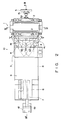
- Fig. 2 is a plan view of the apparatus
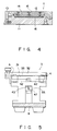
- Fig. 3 is a cross-sectional view of the apparatus, taken along line III-III in Fig. 2.
- Fig. 4 is also a cross-sectional view of the apparatus, taken along line VI-VI in Fig. 2.
- Fig. 5 is a partially sectional side view of the apparatus, taken along line V-V in Fig. 2.
- the cable-aligning apparatus 10 comprises a frame 8, a clamper 1, a cable-aligning table 3, an elevator 6, and a table 18.
- the clamper 1, the tables 1 and 3, and the elevator 6 are mounted on the frame 8.
- the clamper 1 and the cable-aligning table 3 are located close to each other, and the table 3 and the elevator 6 are spaced apart from each other, with a space 9 between them.
- two coil springs 2 are located on the left and right sides of the clamper 1.
- the coil springs 2 are used to hold single-fiber cables among their turns.
- the cable holder 7 is mounted on the elevator 6.
- the clamper 1 is designed to hold single-fiber cables. As is illustrated in Fig. 4, the clamper 1 comprises a base 11, a cover 12 hinged to the base 11, a fastener 13 for fastening the cover 12 to the base 11, thereby to hold cover 12 in the closed position, a holding plate 14 connected to the inner surface of the cover 12 by springs, and two rubber plates 15 and 16 bonded to the base 11 and the plate 14, respectively.
- the cover 12 When the cover 12 is set in the closed position after single-fiber cables are placed on the base 11, the cables are clamped between the rubbers plates 15 and 16 since the holding plate 14 is biased toward the base 11 by the springs.
- the cable-aligning table 3 comprises a base 31 and a cover 32 hinged to the base 31.
- a gap 33 is formed between the base 31 and the cover 32.
- This gap is substantially equal to the diameter of the single-fiber cables to be aligned. More specifically, the gap is about 0.3 mm when the cables have a diameter of 0.25 mm as most single-fiber cables commonly used at present.
- Two cable-aligning arms 4 are inserted in the gap 33 between the base 31 and the cover 32.
- the arms 4 have a thickness less than the gap 33, and are rotatably supported by two pins 41, respectively.
- Those end portions of the arms 4, which are close to the pins 41, are coupled to two link members 42, respectively.
- These link members 42 are connected to each other by a pin 43 and can rotate around this pin 43.
- These pins 43 are rotatably attached to a movable block 45 which is biased toward the right (Fig. 3) by a spring 46.
- a shaft 47 is fastened to the movable block 45.
- a handle 5 is coupled to the free end of the shaft 47.
- a engagement plate 51 is connected to the handle 5.
- the plate 51 When the handle 5 is rotated in one direction, the plate 51 is moved to the left (Fig. 3) and goes into engagement with a hook 52 fixed to the right side of the frame 8. When the handle 5 is rotated in the opposite direction, the plate 51 is moved to the right and comes out of engagement with the hook 52.
- the elevator 6 has a lever 61.
- the elevator 6 is used to raise the cable holder 7 to a predetermined level.
- the elevator 6 is put in a lowered position, as is represented by two-dot, one-dash lines in Fig. 3. While the elevator 6 remains in the lowered position, the single-fiber cables 101 to 105 of the second group are aligned and held by the holder 7. Then, the lever 61 is rotated downward, thus raising the cable holder 7 to the predetermined level.
- This table 18 is used for supporting the end portions of the single-fiber cables 101 to 105 held by the cable holder 7.
- the table 18 is located, with its left edge located at a distance of, for example, 40 mm from the left end of the cable holder 7.
- those portions of them which extend from the the left end of the holder 7 have the same length of 40 mm.
- those portions of the cables 101 to 105 which extend from the left edge of the cable-aligning table 3 are of the same length. This makes it easier than otherwise to mount the reinforcing tubes 121 to 125 onto these portions of the cables 101 to 105, while the cables 101 to 105 are being aligned by means of the cable-aligning table 3.
- the space 9 allows for the mounting of the tubes 121 to 125 onto the single-fiber cables 101 to 105. It extends at least 40 mm in the horizontal direction.
- the cable-aligning apparatus 10, described above, is operated in the following manner, in order to align the single-fiber cables 101 to 105.
- the handle 5 is rotated until the plate 51 moves to the left, going into engagement with the hook 52.
- the movable block 45 and the shaft 43 are moved to the left, and the link members 42, both coupled to the block 45 by the pins 43, are moved such that both cable-aligning arms 4 are opened.
- the cover 32 of the cable-aligning table 3 is also opened.
- the cover 12 of the clamper 1 is opened.
- the single-fiber cables 101 to 105 are placed on the base 31 of the cable-aligning table 3.
- the reinforcing tubes 121 to 125 are mounted on the single-fiber cables 101 to 105 before these cables are aligned by means of the cable-aligning table 3. Nevertheless, according to the present invention, the tubes can be mounted on the cables 101 to 105 after these cables have been aligned by means of the table 3.
- those portions extending from the left end of the table 3 are straightened up by pushing down the end portions on the table 18 and pulling them away from the table 3 with fingers, and are then aligned parallel to one another by moving the fingers toward or away from one another. While holding these portions of the cables 101 to 105 thus aligned, the operator rotates the lever 61 downward. As a result, the cable holder 7 mounted on the elevator 6 is raised to the predetermined level, to hold the cables 101 to 105.
- the cable holder 7 is of the same structure as the known type designed for holding a multi-fiber cable. As is shown in Fig. 6, the holder 7 comprises a base 71 and two covers 72 hinged to the base 71. One groove 75 is made in the upper surface of the base 71. Pairs of guide pins 74 protrude from the upper surface of the base 71, the two pins 75 of each pair opposing each other across the groove 74. Two cable-pressing member 76 are formed on the inner surfaces of the covers 72, respectively. When these covers 72 are closed, the cable-pressing members 76 press the single-fiber cables 101 to 105, thus firmly holding these cables in the groove 74.
- the upper surface of the base 71 are curved in the lengthwise direction of the groove 74, and the cable-pressing members 76 have a surface curved complemental to the upper surface of the base 71.
- This structural feature increases the friction between the cables placed in the groove 74, on the one hand, and the bottom of the groove 74 and cable-pressing members 76, on the other, thus preventing the cables 101 to 105 from slipping in the groove 74.
- the width of the groove 74 is determined by the number of single-fiber cables to be held together, and the depth of the groove 74 is determined by the diameter of these cables.
- the cable holder is operated to hold the single-fiber cables 101 to 105, in the following way. First, both covers 72 are opened, and the cables 101 to 105 are placed partly in the groove 75 and partly between the guide pins 75. Then, the covers 72 are closed, thus holding the cables 101 to 105 within the groove 74, aligned parallel, in the same fashion as in a multi-fiber cable.
- the single-fiber cables 111 to 115 of the second group are aligned by means of the same cable-aligning apparatus 10, in the same way as the cables 101 to 105 of the first group.
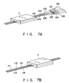
- those end portions of the cables 111 to 115, which are to be fusion-spliced to the cables 101 to 105, are held by a cable holder 7 as is illustrated in Fig. 7B.
- the cables 101 to 105 of the first group and the cables 111 to 115 of the second group, thus held by the holders 7, are processed so as to be fusion-spliced, in the same way as a multi-fiber cable held by the holder of the same type. More specifically, the sheaths are removed from the end portions of the cables of either group, by means of the stripper designed for removing the sheath from a multi-fiber cable. The exposed portions of the optical fibers are cleaned. Then, they are simultaneously cut such that they have flat faces, by means of a cutter for cutting the fibers of the multi-fiber cable (for example, CT-03 manufactured by Fujikura Cable, Co., Ltd.).
- the holder 7 holding the end portions of the cables 101 to 105, and the holder 7 holding the end portions of the cables 111 to 115, are set in a fusion-splicing apparatus designed for fusion-splicing multi-fiber cables, such as FSM-20R manufactured by Fujikura Cable Co., Ltd. More precisely, the end portions of the exposed fibers of the cables 101 to 105 are set in alignment with, and in end-to-end contact with those of the exposed fibers of the cables of the cables 111 to 115. Thereafter, the cables 101 to 105 of the first group 100 and the cables 111 to 115 of the second group 110 are simultaneously fusion-spliced, by operating of the fusion-splicing apparatus.
- the two holders 7 holding the cables 101 to 105 and 111 to 115, which have been fusion-spliced, are removed from fusion-splicing apparatus. Then, the cables 101 to 105 and the cables 111 to 115, now fusion-spliced together, are removed from the holders 7. As a result of this, five long single-fiber cables are made.
- the reinforcing tubes 121 to 125 are moved until they are mounted on the fusion-spliced portions of the long cables.
- the reinforcing tubes 121 to 125 sheathing these fusion-spliced portions are inserted into the grooves 210 to 205 of a reinforcing device 200.
- the power switch 206 of the device 200 is then turned on, whereby the tubes 121 to 125 are heated.
- the reinforcing tubes 121 to 125 which are made of heat-shrinking material, shrink and grip the fusion-spliced portions of the single-fiber cables, reinforcing the fusion-spliced portions.
- the single-fiber cables of either group are aligned parallel to one another by the cable-aligning apparatus 10, and those end portions of these cables thus aligned, which are to be fusion-spliced with the end portions of the single-fiber cables of the other group, are then held by the holder. Therefore, the end portions of the cables of both groups are stripped, cleaned, fusion-spliced, and reinforced -- at the same time. Hence, the cable-aligning apparatus 10 helps to reduce the time for fusion-splicing single-fiber cables.
- one reinforcing tube is sued to reinforce the fusion-spliced end portions of each pair of single-fiber cables.
- the fusion-spliced portions of these cables should better be reinforced by means of a single reinforcing tube 126 made of heat-shrinking material.
- a mold 19 is located right behind the cable holder 7, as is illustrated in Fig. 9. This mold 19 is filled with resin which hardens when irradiated with ultraviolet rays.
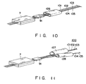
- the single-fiber cables 101 to 105 are placed in the mold 19 and, thus, dipped in the resin filled therein, as is illustrated in Fig. 9. Then, ultraviolet rays are applied to the resin, and the resin hardens, forming a block 91 fastening the cables 101 to 105 together, as is shown in Fig. 10.
- the block 91 is removed from the mold 19, and the single-fiber cables 101 to 105 are removed from the holder 7.
- the single-fiber cables 111 to 115 of the second group 110 are also fastened by a resin block in the same way as the cables 101 to 105, and then removed from the cable holder 7.
- the single-fiber cables of either group can be fastened by means of adhesive tape or adhesive material, instead of the resin. If this is the case, the adhesive tape is wrapped around the cables, thereby fastening the cables aligned parallel in the same plane. Then, the single-fiber cables of either group, thus fastened and aligned, are removed from the cable holder 7.
- the fiber cables can be fastened by means of a paste-like material comprising an inorganic filler, a wetting agent, and a binder.
- the inorganic filler can be calcium hydrogenhosphate or aluminium oxide.
- the wetting agent can be sorbitol solution or propylene glycol.
- the binder can be sodium carboxymethylcellulose.
- the cable 101 to 105, now fastened together by the resin block 91, the adhesive tape or the paste, and the cables 111 to 115, also fastened together by the resin block 91, the adhesive tape or the paste, are set in the fusion-splicing apparatus designed for fusion-splicing multi-fiber cables.
- the fusion-splicing apparatus is operated, thereby fusion-splicing the cables 101 to 105 to the cables 101 to 105, respectively.
- the reinforcing tube 126 is moved to, and mounted on, the fusion-spliced portions of these cables. Then, the tube 126, covering the fusion-spliced portions of the cables, is set in a reinforcing device (not shown) which has only one groove. More precisely, the reinforcing tube 126 is placed in the groove of the device. The power switch of this reinforcing device is turned on, thereby heating the tube 126. The tube 126 shrinks, thus reinforcing the fusion-spliced portions of the cables 101 to 105 and 111 to 115.
- the mold 19 can be located in the space 9, or between the cable-aligning table 3 and the fiber holder 7, so that the single-fiber cables are fastened together by a resin block 91 while they are held parallel to each other by means of the cable holder 7.
- the fusion-spliced portions of some pairs of single-fiber cables are reinforced by a tube, whereas the those of the remaining pairs of the cables are reinforced by another tube.
- a tube which is made of heat-shrinking material
- the other two cables 104 and 105 of the first group 100 are inserted through another reinforcing tube 128 also made of heat-shrinking material, before these cables 101 to 105 are aligned or while they are being aligned.
- the fibers 101 to 105 are held parallel to one another by a cable holder 7 and fastened together by a resin block 91 in the same way as has been described.
- the single-fiber cables 111 to 115 of the second group 111 are aligned and held by a cable holder 7.
- the cables 101 to 105 are fusion-spliced to the cables 111 to 115 by the fusion-splicing apparatus.
- the reinforcing tube 127 is moved to, and mounted on, the fusion-spliced portions of the cables 101 to 103 and 111 to 113, and the reinforcing tube 128 is moved to, and mounted on, those of the cables 104 and 105 and 114 and 115.
- the tube 127 covering the fusion-spliced portions of the cables 101 to 103 and 111 to 113, and the tube 128 covering those of the cables 104 and 105 and 114 and 115, are set in a reinforcing device (not shown) which has two grooves.
- the reinforcing tubes 127 and 128 are placed in the grooves of the device.
- the power switch of the reinforcing device is turned on, thereby heating both tubes 127 and 128.
- the tubes 127 and 128 shrink, thereby reinforcing the fusion-spliced portions of the cables 101 to 105 and 111 to 115.
- the reinforcing tubes 126, 127, and 128, shown in Figs. 10 and 11, have the same structure. They have different sizes in accordance with the number of single-fiber cables they are to hold. Hence, the tubes 127 and 128, which hold three cables and two cables, respectively, are smaller than the tube 126 which holds five cables, and the tube 128 is smaller than the tube 127. Only the reinforcing tube 126 will be described in greater detail with reference to Fig. 12 which is a cross-sectional view.
- the tube 126 comprises two coaxial tubes 129 and 130, both made of heat-shrinking material, and a reinforcing plate 131 made of ceramics, having a crescent cross section, and interposed between the inner tube 129 and the outer tube 130.
- the single-fiber cables 101 to 105 are passed through the inner tube 129.
- the single-fiber cables of either group are held first lightly by the coil springs 2 and then firmly by the clamper 1. If the coil spring 2 located on the right side of the clamper 1 can alone firmly hold the single-fiber cables, neither the clamper 1 nor the other coil spring 2 located on the left side of the clamper 1 is required, as in a cable-aligning apparatus illustrated in Figs. 13 and 14. When this apparatus is used, it is only the coil spring 2 that hold the cables while the operator pulling the cables, while pressing them down on the table 18, in order to align the them parallel to one another and spaced apart from one another.
- the elevator 6 can be replaced by a supporting table of a predetermined height level, which is fixedly mounted on the base plate 8.
- table 18 can be omitted, though in such a case the ends of the fiber cables cannot be accurately aligned.
- the cable-aligning apparatus shown in Figs. 13 and 14 is operated in the same way as the apparatus illustrated in Figs. 2 and 3, except that the single-fiber cables are not held by, or released from, a clamper. Also in view of this, the apparatus is advantageous over the cable-aligning apparatus which is illustrated in Figs. 2 and 3.
- the cable-aligning apparatus 10 shown in Figs. 2 and 3 has coil springs 2 for holding among their turns, the single-fiber cables of either group.
- These coil springs 2 can be replaced by such a brush 22 mounted on the base 21, as is illustrated in Fig. 15. This brush 22 performs the same function as the coil springs 2.
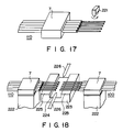
- the sheaths are removed from the end portions of the cables of a second group 110 held by a holder 7, at a time, by means of the sheath remover of the fusion-splicing apparatus, which comprises a pair of blades 220. More specifically, the blades 220, located one above the outer, are moved in the vertical direction, toward them until they bite into the sheaths of the cables. Then, the remover is moved in the horizontal direction as is indicated by the arrows in Fig. 16, thereby removing the sheaths, thereby exposing the end portions of the optical fibers. Although the cutting edge of either blade 220 appears straight in Fig. 16, it has semicircular grooves so that the blade 220 does not cut the optical fibers of the cables.
- the exposed end portions of the fibers are cut simultaneously by the cutter 221 of the fusion-splicing apparatus, so that they have flat faces.
- the sheaths are removed from the end portions of the single-fiber cables of a first group 100 by means of the sheath remover of the fusion-splicing apparatus, in the same way as the cables of the second group 110. Further, the exposed end portions of the fibers are cut by the cutter 221 of the fusion-splicing apparatus, so that they have flat faces, also in the same way as those of the optical fibers of the second group 110.
- the end portions of the cables of the first group 100, held by the holder 7, and those of the cables of the second group 110, also held by the other holder 7, are placed on the support 222 of the fusion-splicing apparatus, in the same plane.
- the support 222 has a U-groove defining two flat portions 223 and 224 of the support 222.
- Two clampers (not shown) are mounted on the flat portions 223 and 224 of the support 222, respectively.
- the clampers on the flat portions 223 and 225 hold the exposed optical fibers of both groups 100 and 110, such that the fibers of the first group 100 are set opposite to, and in coaxial alignment with, those of the second group 110.
- the fusion-splicing apparatus has a pair of electrodes 225 which oppose each other and extend into the U-groove of the support 222. A high voltage is applied across the electrodes for a predetermined time, thus generating an electrical arc between these electrodes. Because of this arc, the ends of the optical fibers of both group are heated, and fused together. Upon lapse of the predetermined time, the application of the voltage to the electrodes is stopped. The fused portions of each pair of optical fibers are cooled, whereby the single-fiber cables of the first group 100 are fusion-spliced to those of the second group 110, by means of the fusion-splicing apparatus.
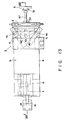
- FIG. 19-24 A cable-aligning apparatus according to a further embodiment of this invention is shown in Figs. 19-24.
- the link members used in the former-recited embodiment are replaced by pawl members 231.
- the pawl members 231 are moved by means of a rack and pinion arrangement. Specifically, the pawl member 231 are mounted on top of stem members 232 by means of screws 234. The stem members 232 are mounted on one ends of racks 233 by means of screws (not shown). The pawl members 231 are positioned on the cable-aligning table 3, and fiber cables are arranged between the pawl members 231. The racks 233 are engaged with a pinion 235.
- One of the racks 233 is pushed toward the center of the apparatus by means of a spring 236 provided between one end of the rack and the wall of the apparatus, so that the racks 233 are normally urged in directions opposite to each other and set in their normal positions. With the racks set in their normal positions, the pawl members 231 contact each other.
- a shaft 237 is fastened to the pinion 235.
- a handle 238 is fastened to the shaft 237.
- the pinion 235 is rotated in the direction to move the racks 233 from their normal positions toward the outward of the apparatus.
- a notch 239 formed in the side wall of one of the racks 233 is engaged with a projecting member 240 to hold the rack 233 at the position.
- a recess 241 is formed in the inner surface of a cover 242 for the aligning table 3.
- the recess 241 accommodates the heads of the screws 234 mounting the pawl members 231 to the racks 233, when the cover 242 is set in the closed position.
- the gap formed between the base and the cover of the table 3 is substantially equal to the diameter of the cables 101 to 105, as in the previous embodiments. Therefore, none of the cables is forced upward such that it rode atop another.
- the cover 242 has a knob 258 made of metal, and the aligning table 3 has a magnet 259 on the top. Therefore, the cover 241 is attracted to the aligning table 3, when set in the closed position, by means of the magnetic force of the magnet 259.
- the handle 238 is rotated in the predetermined direction to rotate the pinion 235 in the direction.
- the racks 233 are moved toward the outward of the apparatus from the normal positions, so that the pawl members 231 are moved to the far from each other.
- the racks are held at the positions.
- the fiber cables are arranged on the aligning table 3 and between the pawl members 231.
- the handle 238 is rotated in the opposite direction so that the rack 233 is rendered to be out-of-engagement with the projecting member 240.
- the racks 233 are pushed toward the center of the apparatus by means of the spring 236, so that the pawl members 231 are to be close to each other. Therefore, the fiber cables arranged between the pawl members 231 are put together and aligned parallel.
- supporting table 250 and supporting base 251 of the cable holder are retractable.
- a slide member 252 is mounted on the lower portion of the supporting base 251.
- the slide member 252 is held by means of a holder 253, and can be slid on the base plate 8 of the apparatus.
- the supporting table 250 and the supporting base 251 are on the main plate 8 and abut on the side wall of the aligning table device, as shown in Fig. 19 and 20.
- a lever 254 of a slider lock 255 is rotated downwardly, so that a locking shaft 256 abuts against the slide member 252 to lock the slide member.
- the supporting table 250 and the supporting base 251 are pulled outwardly, as shown in Figs. 23 and 24.
- the slide member 252 is slide on the base plate 8, and moved outwardly via the slide holder 253 until the hook 257 of the slide member 252 is engaged with the front end of the slide holder 253.
- a space 9 is formed between the supporting table 250 and the aligning table 3. The space 9 allows for the mounting of the reinforcing tubes onto the fiber cables.
- the present invention provides a method of simultaneously aligning a plurality of single-fiber cables in parallel by a simple operation without requiring long excess portions of the cables, making it possible to hold the cables, thus aligned, by means of a holder of the known type designed for holding a multi-fiber cable.
- This invention also provides an apparatus which is small and easy to operate, and can align a plurality of single-fiber cables in parallel to each other without requiring long excess portions of the cables, making it possible to hold the cables, thus aligned, by means of a holder of the known type designed for holding a multi-fiber cable.
- the excess portion of each cable which is required to align the cable parallel to the other cables by the method and apparatus according to the present invention, is shorter than is required in the conventional method and apparatus. Although this excess portion is about 40 mm long in the embodiments described above, it can be either shorter or longer than this exemplary value.
- the present invention provides a method of simultaneously fusion-splicing the single-fiber cables of a group to those of another group, the cables of either group having been aligned parallel to one another by means of the cable-aligning apparatus according to the present invention.
Landscapes
- Physics & Mathematics (AREA)
- General Physics & Mathematics (AREA)
- Optics & Photonics (AREA)
- Engineering & Computer Science (AREA)
- Plasma & Fusion (AREA)
- Mechanical Coupling Of Light Guides (AREA)
Claims (13)
- Vorrichtung, um mehrere Einzelfaser-Kabel parallel und miteinander in Kontakt stehend auszurichten, wobei die Vorrichtung aufweist:
eine Grundplatte (31) mit einer ersten flachen Oberfläche;
eine Deckelplatte (32), die eine zweite flache Oberfläche aufweist und an der Grundplatte angelenkt ist und geschlossen zusammen mit der Grundplatte zwischen den flachen Oberflächen einen Spalt bildet, wobei der Spalt im wesentlichen gleich dem Durchmesser der Einzelfaser-Kabel ist; und
ein Paar von Armen (4), deren Dicke kleiner als der Spalt ist und welche in den Spalt eingesetzt sind und innerhalb des Spalts gegeneinander beweglich sind, um so die Einzelfaser-Kabel in dem Spalt parallel und in Kontakt miteinander in einer Ebene auszurichten. - Verfahren, um mehrere Einzelfaser-Kabel parallel und miteinander in Kontakt stehend auszurichten, das die Vorrichtung gemäß Anspruch 1 verwendet und die Schritte aufweist:
Auflegen von Einzelfaser-Kabeln (101 bis 105, 111 bis 115) auf die flache Oberfläche der Grundplatte (31);
Schließen der Deckelplatte (32) und dadurch Einführen der Einzelfaser-Kabel in den Spalt zwischen der Grundplatte und der Deckelplatte, wobei der Spalt im wesentlichen dem Durchmesser der Einzelfaser-Kabel (101 bis 105, 111 bis 115) gleich ist; und
Bewegen des in den Spalt eingeführten Paares von Armen (4) gegeneinander und dadurch Ausrichten der Einzelfaser-Kabel parallel und in Kontakt miteinander in einer Ebene. - Verfahren nach Anspruch 2, das ferner den Schritt des Halterns der ausgerichteten Einzelfaser-Kabel mittels einer Kabelhalterung 7 aufweist.
- Verfahren nach Anspruch 2, das ferner den Schritt des Durchführens der Einzelfaser-Kabel durch Verstärkungsschläuche (121 bis 125, 126 bis 128), bevor oder nachdem die Einzelfaser-Kabel in den Spalt eingelegt werden, aufweist.
- Verfahren zum Schmelzspleißen mehrerer Einzelfaser-Kabel, das die Schritte aufweist:
Durchführen von Einzelfaser-Kabeln (101 bis 105) einer ersten Gruppe (100) durch aus wärmeschrumpfenden Material hergestellte Verstärkungsschläuche (121 bis 125, 126 bis 128);
Ausrichten der Kabel der ersten Gruppe und auch der Einzelfaser-Kabel (111 bis 115) einer zweiten Gruppe (110) mittels der Kabelausrichtevorrichtung (10) nach Anspruch 1;
Haltern der Kabel beider Gruppen mittels zweier Kabelhalterungen (7);
Einsetzen der Faserhalterungen in eine für das Schmelzspleißen von Mehrfach-Kabeln ausgelegte Schmelzspleiß-Vorrichtung in der Weise, daß die Enden der Kabel der ersten Gruppe denen der Kabel der zweiten Gruppe gegenüberliegen;
Betreiben der Schmelzspleiß-Vorrichtung und dadurch gleichzeitiges Schmelzverspleißen der Kabel der ersten Gruppe mit den Kabeln der zweiten Gruppe;
Schieben der Verstärkungsschläuche über die schmelzverspleißten Kabelabschnitte beider Gruppen; und
Aufheizen der Verstärkungsschläuche, um die Schläuche zu schrumpfen und damit gleichzeitig die schmelzverspleißten Kabelabschnitte beider Gruppen zu verstärken. - Verfahren nach Anspruch 5, wobei der Schritt des Ausrichtens der Kabel beider Gruppen die Schritte aufweist:
Auflegen von Einzelfaser-Kabeln auf die Basis der Kabelausrichtevorrichtung;
Schließen der Deckelplatte (32) der Kabelausrichtevorrichtung, und dadurch Einführen der Einzelfaser-Kabel in einen Spalt zwischen der Basis und dem Deckel, wobei der Spalt im wesentlichen dem Durchmesser der Einzelfaser-Kabel gleich ist; und
Bewegen der Arme (4) der Kabelausrichtevorrichtung gegeneinander und dadurch Ausrichten der Einzelfaser-Kabel parallel und in Kontakt miteinander in einer Ebene. - Vorrichtung, um mehrere Einzelfaser-Kabel parallel und miteinander in Kontakt stehend auszurichten, wobei die Vorrichtung aufweist:
eine Grundplatte (31) mit einer ersten flachen Oberfläche;
eine Deckelplatte (242), die eine zweite flache Oberfläche aufweist und an der Grundplatte angelenkt ist und geschlossen zusammen mit der Grundplatte zwischen den flachen Oberflächen einen Spalt bildet, wobei der Spalt im wesentlichen gleich dem Durchmesser der Einzelfaser-Kabel (101 bis 105, 111 bis 115) ist; und
ein Paar von Klinkenelementen (231), deren Dicke kleiner als der Spalt ist und welche in den Spalt eingesetzt sind und innerhalb des Spalt gegeneinander beweglich sind, um so die Einzelfaser-Kabel in dem Spalt parallel und in Kontakt zueinander in einer Ebene auszurichten. - Vorrichtung nach Anspruch 7, die ferner eine mit den Klinkenelementen verbundene Zahnstangen- und Ritzel-Anordnung (233, 235) aufweist, um eine Antriebskraft auf die Klinkenelemente zum Bewegen der Elemente zu übertragen.
- Verfahren, um mehrere Einzelfaser-Kabel parallel und miteinander in Kontakt stehend auszurichten, das die Vorrichtung nach Anspruch 7 verwendet und die Schritte aufweist:
Auflegen von Einzelfaser-Kabeln (101 bis 105, 111 bis 115) auf die flache Oberfläche der Grundplatte (31);
Schließen der Deckelplatte (242) und dadurch Einführen der Einzelfaser-Kabel (101 bis 105, 111 bis 115) in den Spalt zwischen der Grundplatte und der Deckelplatte, wobei der Spalt im wesentlichen dem Durchmesser der Einzelfaser-Kabel (101 bis 105, 111 bis 115) gleich ist; und
Bewegen des in den Spalt eingesetzten Paares der Klinkenelemente (231) und dadurch Ausrichten der Einzelfaser-Kabel parallel und in Kontakt miteinander in einer Ebene. - Verfahren nach Anspruch 9, das ferner den Schritt des Halterns der ausgerichteten Einzelfaser-Kabel mittels einer Kabelhalterung 7 aufweist.
- Verfahren nach Anspruch 9, das ferner den Schritt des Durchführens der Einzelfaser-Kabel durch Verstärkungsschläuche (121 bis 125, 126 bis 128), bevor oder nachdem die Einzelfaser-Kabel in den Spalt eingelegt werden, aufweist.
- Verfahren zum Schmelzspleißen mehrerer Einzelfaser-Kabel, das die Schritte aufweist:
Durchführen von Einzelfaser-Kabeln (101 bis 105) einer ersten Gruppe (100) durch aus wärmeschrumpfenden Material hergestellte Verstärkungsschläuche (121 bis 125, 126 bis 128);
Ausrichten der Kabel der ersten Gruppe und auch der Einzelfaser-Kabel (111 bis 115) einer zweiten Gruppe (110) mittels der Kabelausrichtevorrichtung (10) nach Anspruch 7;
Haltern der Kabel beider Gruppen mittels zweier Kabelhalterungen (7);
Einsetzen der Faserhalterungen in eine für das Schmelzspleißen von Mehrfach-Kabeln ausgelegte Schmelzspleiß-Vorrichtung in der Weise, daß die Enden der Kabel der ersten Gruppe denen der Kabel der zweiten Gruppe gegenüberliegen;
Betreiben der Schmelzspleiß-Vorrichtung und dadurch gleichzeitiges Schmelzverspleißen der Kabel der ersten Gruppe mit den Kabeln der zweiten Gruppe;
Schieben der Verstärkungsschläuche über die schmelzverspleißten Kabelabschnitte beider Gruppen; und Aufheizen der Verstärkungsschläuche, um die Schläuche zu schrumpfen und damit gleichzeitig die schmelzverspleißten Kabelabschnitte beider Gruppen zu verstärken. - Verfahren nach Anspruch 12, wobei der Schritt des Ausrichtens der Kabel beider Gruppen die Schritte aufweist:
Auflegen von Einzelfaser-Kabeln auf die Basis der Kabelausrichtevorrichtung;
Schließen der Deckelplatte (242) der Kabelausrichtevorrichtung und dadurch Einführen der Einzelfaser-Kabel in einen Spalt zwischen der Basis und dem Deckel, wobei der Spalt im wesentlichen dem Durchmesser der Einzelfaser-Kabel gleich ist; und
Bewegen der Klinkenelemente (231) gegeneinander und dadurch Ausrichten der Einzelfaser-Kabel in derselben Ebene.
Applications Claiming Priority (4)
| Application Number | Priority Date | Filing Date | Title |
|---|---|---|---|
| JP22398888A JPH0272305A (ja) | 1988-09-07 | 1988-09-07 | 複数単心光ファイバの一括接続法 |
| JP223989/88 | 1988-09-07 | ||
| JP223988/88 | 1988-09-07 | ||
| JP22398988A JPH0272306A (ja) | 1988-09-07 | 1988-09-07 | 光ファイバ整列装置及び光ファイバ接続法 |
Publications (3)
| Publication Number | Publication Date |
|---|---|
| EP0358214A2 EP0358214A2 (de) | 1990-03-14 |
| EP0358214A3 EP0358214A3 (de) | 1991-09-11 |
| EP0358214B1 true EP0358214B1 (de) | 1995-12-13 |
Family
ID=26525786
Family Applications (1)
| Application Number | Title | Priority Date | Filing Date |
|---|---|---|---|
| EP89116547A Expired - Lifetime EP0358214B1 (de) | 1988-09-07 | 1989-09-07 | Methode und Vorrichtung für die Justierung einer Vielzahl faseroptischer Kabel und Methode des gleichzeitigen Spleissens solcher Kabel |
Country Status (3)
| Country | Link |
|---|---|
| US (1) | US5046813A (de) |
| EP (1) | EP0358214B1 (de) |
| DE (1) | DE68925084T2 (de) |
Cited By (1)
| Publication number | Priority date | Publication date | Assignee | Title |
|---|---|---|---|---|
| KR101457136B1 (ko) * | 2014-03-17 | 2014-10-31 | 주식회사 디에스아이 | 케이블용 다중관의 내관 히팅장치 |
Families Citing this family (25)
| Publication number | Priority date | Publication date | Assignee | Title |
|---|---|---|---|---|
| US5170456A (en) * | 1988-09-07 | 1992-12-08 | Fujikura Ltd. | Apparatus for aligning a plurality of single-fiber cables |
| GB9106981D0 (en) * | 1991-04-03 | 1991-05-22 | Bicc Plc | Optical fibre splicing |
| EP0681707B1 (de) * | 1993-11-29 | 1999-10-13 | Telefonaktiebolaget Lm Ericsson | Bestimmung des winkelversutzes zwischen optischen fasern mit optischer, axialer asymmetrie und ausrichtung und spleissen von solchen fasern |
| SE502563C2 (sv) * | 1994-03-08 | 1995-11-13 | Ericsson Telefon Ab L M | Sätt och anordning för att skarva optiska fibrer, samt användning av sättet för framställning av en skarv med förutbestämd dämpning |
| US6207922B1 (en) | 1994-03-08 | 2001-03-27 | Telefonaktiebolaget Lm Ericsson (Publ) | Electric control for welding optical fibers |
| SE512382C2 (sv) * | 1994-04-26 | 2000-03-06 | Ericsson Telefon Ab L M | Anordning och förfarande för att placera långsträckta element mot eller invid en yta |
| SE511820C2 (sv) * | 1997-05-23 | 1999-11-29 | Ericsson Telefon Ab L M | Anordning för hopsvetsning av optiska fibrer |
| KR100406864B1 (ko) | 1999-01-19 | 2003-11-21 | 삼성전자주식회사 | 광섬유 블럭의 광학적 정렬도 측정 장치 및 방법 |
| US6266472B1 (en) | 1999-09-03 | 2001-07-24 | Corning Incorporated | Polymer gripping elements for optical fiber splicing |
| US7190865B2 (en) * | 2004-04-19 | 2007-03-13 | Infinera Corporation | Hermaphroditic u-guide alignment structures and method thereof |
| EP1892547B8 (de) * | 2005-06-09 | 2012-02-29 | Sumitomo Electric Industries, Ltd. | Spleissschutzheizungsvorrichtung,Verschmelzungsspleisser und Verfahren zum Verschmelzungsspleissen von optischen Fasern |
| SE530854C2 (sv) | 2005-12-30 | 2008-09-30 | Ericsson Telefon Ab L M | Inriktning av optiska fibrer vid dessas skarvning |
| SE529875C2 (sv) * | 2005-12-30 | 2007-12-18 | Ericsson Telefon Ab L M | Placering av optiska fibrer i läge |
| CN101375191B (zh) * | 2005-12-30 | 2012-10-10 | 艾利森电话股份有限公司 | 光纤的位置确定 |
| SE530730C2 (sv) | 2005-12-30 | 2008-08-26 | Ericsson Telefon Ab L M | Inriktning av optiska fibrer vid dessas skarvning |
| US7926797B2 (en) | 2007-10-17 | 2011-04-19 | Adc Telecommunications, Inc. | Cable splint |
| US8998511B2 (en) | 2008-07-08 | 2015-04-07 | Telefonaktiebolaget L M Ericsson (Publ) | Cladding alignment for fusion splicing optical fibers |
| US8485735B2 (en) * | 2008-12-19 | 2013-07-16 | US Conec, Ltd | Field install fiber clip and method of use |
| WO2011119682A1 (en) * | 2010-03-23 | 2011-09-29 | Afl Telecommunications, Llc | Bare glass fiber holder |
| ES2703235T3 (es) | 2011-11-23 | 2019-03-07 | Adc Telecommunications Inc | Conector de fibra óptica multi-fibra |
| CN104364686B (zh) | 2012-02-07 | 2016-11-16 | 泰科电子瑞侃有限公司 | 用于连接器的线缆端接组件和方法 |
| CA2864886A1 (en) | 2012-02-20 | 2013-08-29 | Adc Telecommunications, Inc. | Fiber optic connector, fiber optic connector and cable assembly, and methods for manufacturing |
| US8939654B2 (en) | 2012-09-27 | 2015-01-27 | Adc Telecommunications, Inc. | Ruggedized multi-fiber fiber optic connector with sealed dust cap |
| US9720185B2 (en) | 2014-05-23 | 2017-08-01 | Commscope Technologies Llc | Systems and method for processing optical cable assemblies |
| JP6586153B2 (ja) | 2017-12-25 | 2019-10-02 | 株式会社フジクラ | 光ファイバ集合体の製造方法 |
Citations (1)
| Publication number | Priority date | Publication date | Assignee | Title |
|---|---|---|---|---|
| EP0278423A2 (de) * | 1987-02-06 | 1988-08-17 | Sumitomo Electric Industries Limited | Vorrichtung für die Anordnung einer Vielzahl optischer Fasern und Methode für deren gemeinsames Lichtbogenspleissen unter Verwendung dieser Vorrichtung |
Family Cites Families (9)
| Publication number | Priority date | Publication date | Assignee | Title |
|---|---|---|---|---|
| US3919037A (en) * | 1974-11-07 | 1975-11-11 | Bell Telephone Labor Inc | Optical fiber splicing apparatus |
| FR2367295A1 (fr) * | 1976-10-05 | 1978-05-05 | Cables De Lyon Geoffroy Delore | Procede et disposit |
| JPS55155314A (en) * | 1979-05-21 | 1980-12-03 | Nippon Telegr & Teleph Corp <Ntt> | Connecting method of optical fiber and its connector |
| US4274707A (en) * | 1979-06-14 | 1981-06-23 | Northern Telecom Limited | Apparatus for fusion splicing of optical fibers |
| JPS623208A (ja) * | 1985-06-28 | 1987-01-09 | Sumitomo Electric Ind Ltd | 光フアイバの接続方法 |
| GB8523157D0 (en) * | 1985-09-19 | 1985-10-23 | Bicc Plc | Optical fibre splicing |
| GB8611361D0 (en) * | 1986-05-09 | 1986-06-18 | Bicc Plc | Splicing optical fibre ribbon |
| DE3789751T2 (de) * | 1986-10-27 | 1994-12-22 | The Furukawa Electric Co., Ltd., Tokio/Tokyo | Vorrichtung zum axialen Zentrieren beim Verschmelzen optischer Fasern. |
| US5013345A (en) * | 1987-12-04 | 1991-05-07 | Fujikura Ltd. | Method of fusion-splicing polarization maintaining optical fibers |
-
1989
- 1989-09-01 US US07/402,896 patent/US5046813A/en not_active Expired - Lifetime
- 1989-09-07 DE DE68925084T patent/DE68925084T2/de not_active Expired - Lifetime
- 1989-09-07 EP EP89116547A patent/EP0358214B1/de not_active Expired - Lifetime
Patent Citations (1)
| Publication number | Priority date | Publication date | Assignee | Title |
|---|---|---|---|---|
| EP0278423A2 (de) * | 1987-02-06 | 1988-08-17 | Sumitomo Electric Industries Limited | Vorrichtung für die Anordnung einer Vielzahl optischer Fasern und Methode für deren gemeinsames Lichtbogenspleissen unter Verwendung dieser Vorrichtung |
Cited By (1)
| Publication number | Priority date | Publication date | Assignee | Title |
|---|---|---|---|---|
| KR101457136B1 (ko) * | 2014-03-17 | 2014-10-31 | 주식회사 디에스아이 | 케이블용 다중관의 내관 히팅장치 |
Also Published As
| Publication number | Publication date |
|---|---|
| DE68925084D1 (de) | 1996-01-25 |
| DE68925084T2 (de) | 1996-05-30 |
| US5046813A (en) | 1991-09-10 |
| EP0358214A3 (de) | 1991-09-11 |
| EP0358214A2 (de) | 1990-03-14 |
Similar Documents
| Publication | Publication Date | Title |
|---|---|---|
| EP0358214B1 (de) | Methode und Vorrichtung für die Justierung einer Vielzahl faseroptischer Kabel und Methode des gleichzeitigen Spleissens solcher Kabel | |
| US5170456A (en) | Apparatus for aligning a plurality of single-fiber cables | |
| US10444435B2 (en) | Ribbon transition tool | |
| KR20050013670A (ko) | 광섬유 절단 장치 | |
| WO2002004998A1 (en) | Optical fiber wire holder, fused connection device, cutting device, and method of connecting optical fiber | |
| US5681417A (en) | Method and device for stripping optical fibre ribbons | |
| JPH0438108A (ja) | 被覆電線の中間皮剥き方法 | |
| EP0576850A1 (de) | Selbständige Einheit und Verfahren zum Zusammenspleissen von optischen Fasern | |
| JPH0854522A (ja) | 単心光ファイバの集合方法及びテープ化装置 | |
| US4548669A (en) | Light waveguide welding device | |
| US4379771A (en) | Methods of and apparatus for terminating a lightguide fiber ribbon | |
| CA2596704C (en) | Optical fibre cleaving device | |
| JPH1039161A (ja) | 光ファイバ融着接続機 | |
| JPH0625806U (ja) | 複数のファイバーをリボンに結束する装置 | |
| JPH0690342B2 (ja) | 光フアイバ融着接続装置 | |
| JPH0272305A (ja) | 複数単心光ファイバの一括接続法 | |
| JP3428477B2 (ja) | 光ファイバの被覆除去装置 | |
| JPS614004A (ja) | 光フアイバ−括切断機構および切断方法 | |
| JP3844595B2 (ja) | 光ファイバの被覆除去装置 | |
| JP3497602B2 (ja) | 光ファイバ端末処理工具 | |
| JP3475034B2 (ja) | 光ファイバ融着接続装置 | |
| JP3834133B2 (ja) | 光ファイバテープ心線の被覆除去器およびその操作方 法 | |
| JPH07104452B2 (ja) | 多心被覆光フアイバ融着接続用クランプ方法 | |
| JPH10288716A (ja) | 単心光ファイバの融着接続方法 | |
| DE2932754C3 (de) | Einspannvorrichtung für Lichtwellenleiter zur Herstellung von unlösbaren Verbindungen |
Legal Events
| Date | Code | Title | Description |
|---|---|---|---|
| PUAI | Public reference made under article 153(3) epc to a published international application that has entered the european phase |
Free format text: ORIGINAL CODE: 0009012 |
|
| 17P | Request for examination filed |
Effective date: 19890907 |
|
| AK | Designated contracting states |
Kind code of ref document: A2 Designated state(s): DE GB SE |
|
| PUAL | Search report despatched |
Free format text: ORIGINAL CODE: 0009013 |
|
| AK | Designated contracting states |
Kind code of ref document: A3 Designated state(s): DE GB SE |
|
| 17Q | First examination report despatched |
Effective date: 19931104 |
|
| GRAA | (expected) grant |
Free format text: ORIGINAL CODE: 0009210 |
|
| AK | Designated contracting states |
Kind code of ref document: B1 Designated state(s): DE GB SE |
|
| REF | Corresponds to: |
Ref document number: 68925084 Country of ref document: DE Date of ref document: 19960125 |
|
| PLBE | No opposition filed within time limit |
Free format text: ORIGINAL CODE: 0009261 |
|
| STAA | Information on the status of an ep patent application or granted ep patent |
Free format text: STATUS: NO OPPOSITION FILED WITHIN TIME LIMIT |
|
| 26N | No opposition filed | ||
| REG | Reference to a national code |
Ref country code: GB Ref legal event code: IF02 |
|
| PGFP | Annual fee paid to national office [announced via postgrant information from national office to epo] |
Ref country code: GB Payment date: 20080910 Year of fee payment: 20 |
|
| PGFP | Annual fee paid to national office [announced via postgrant information from national office to epo] |
Ref country code: DE Payment date: 20080925 Year of fee payment: 20 |
|
| PGFP | Annual fee paid to national office [announced via postgrant information from national office to epo] |
Ref country code: SE Payment date: 20080916 Year of fee payment: 20 |
|
| REG | Reference to a national code |
Ref country code: GB Ref legal event code: PE20 Expiry date: 20090906 |
|
| EUG | Se: european patent has lapsed | ||
| PG25 | Lapsed in a contracting state [announced via postgrant information from national office to epo] |
Ref country code: GB Free format text: LAPSE BECAUSE OF EXPIRATION OF PROTECTION Effective date: 20090906 |