EP0357825A1 - Dispositiv de raclage pour machine d'impression en héliogravure - Google Patents
Dispositiv de raclage pour machine d'impression en héliogravure Download PDFInfo
- Publication number
- EP0357825A1 EP0357825A1 EP88114700A EP88114700A EP0357825A1 EP 0357825 A1 EP0357825 A1 EP 0357825A1 EP 88114700 A EP88114700 A EP 88114700A EP 88114700 A EP88114700 A EP 88114700A EP 0357825 A1 EP0357825 A1 EP 0357825A1
- Authority
- EP
- European Patent Office
- Prior art keywords
- support member
- holding member
- doctor blade
- wiping roller
- wiping
- Prior art date
- Legal status (The legal status is an assumption and is not a legal conclusion. Google has not performed a legal analysis and makes no representation as to the accuracy of the status listed.)
- Granted
Links
- 230000007246 mechanism Effects 0.000 claims abstract description 22
- 239000012530 fluid Substances 0.000 claims abstract description 19
- 230000006835 compression Effects 0.000 claims abstract description 13
- 238000007906 compression Methods 0.000 claims abstract description 13
- 230000003449 preventive effect Effects 0.000 claims abstract description 4
- 238000004140 cleaning Methods 0.000 claims description 25
- 230000008878 coupling Effects 0.000 claims description 7
- 238000010168 coupling process Methods 0.000 claims description 7
- 238000005859 coupling reaction Methods 0.000 claims description 7
- 239000000976 ink Substances 0.000 description 20
- 239000002184 metal Substances 0.000 description 13
- 229910052751 metal Inorganic materials 0.000 description 13
- 230000000694 effects Effects 0.000 description 2
- 238000005096 rolling process Methods 0.000 description 2
- RYGMFSIKBFXOCR-UHFFFAOYSA-N Copper Chemical compound [Cu] RYGMFSIKBFXOCR-UHFFFAOYSA-N 0.000 description 1
- 229920001875 Ebonite Polymers 0.000 description 1
- 230000009471 action Effects 0.000 description 1
- 230000008859 change Effects 0.000 description 1
- 239000003086 colorant Substances 0.000 description 1
- 238000011109 contamination Methods 0.000 description 1
- 229910052802 copper Inorganic materials 0.000 description 1
- 239000010949 copper Substances 0.000 description 1
- 230000003247 decreasing effect Effects 0.000 description 1
- 230000000593 degrading effect Effects 0.000 description 1
- 230000006866 deterioration Effects 0.000 description 1
- 238000004090 dissolution Methods 0.000 description 1
- 238000003780 insertion Methods 0.000 description 1
- 230000037431 insertion Effects 0.000 description 1
- 230000002452 interceptive effect Effects 0.000 description 1
- 238000012986 modification Methods 0.000 description 1
- 230000004048 modification Effects 0.000 description 1
- 230000001105 regulatory effect Effects 0.000 description 1
- 238000000926 separation method Methods 0.000 description 1
- 229920003051 synthetic elastomer Polymers 0.000 description 1
- 239000005061 synthetic rubber Substances 0.000 description 1
Images


Classifications
-
- B—PERFORMING OPERATIONS; TRANSPORTING
- B41—PRINTING; LINING MACHINES; TYPEWRITERS; STAMPS
- B41F—PRINTING MACHINES OR PRESSES
- B41F9/00—Rotary intaglio printing presses
- B41F9/06—Details
- B41F9/08—Wiping mechanisms
- B41F9/10—Doctors, scrapers, or like devices
-
- B—PERFORMING OPERATIONS; TRANSPORTING
- B41—PRINTING; LINING MACHINES; TYPEWRITERS; STAMPS
- B41F—PRINTING MACHINES OR PRESSES
- B41F13/00—Common details of rotary presses or machines
- B41F13/08—Cylinders
- B41F13/24—Cylinder-tripping devices; Cylinder-impression adjustments
- B41F13/34—Cylinder lifting or adjusting devices
- B41F13/40—Cylinder lifting or adjusting devices fluid-pressure operated
-
- B—PERFORMING OPERATIONS; TRANSPORTING
- B41—PRINTING; LINING MACHINES; TYPEWRITERS; STAMPS
- B41F—PRINTING MACHINES OR PRESSES
- B41F9/00—Rotary intaglio printing presses
- B41F9/06—Details
- B41F9/08—Wiping mechanisms
- B41F9/10—Doctors, scrapers, or like devices
- B41F9/1018—Doctors, scrapers, or like devices using a wiping cylinder
Definitions
- the present invention relates to a wiping apparatus for wiping an excessive ink included in an ink supplied to a copperplate surface and attached to a portion except for a picture pattern in each printing cycle.
- An intanglio printing press includes a copperplate cylinder on which a copperplate is mounted and an impression cylinder which is in contact with the copperplate.
- An image of an ink supplied to the outer surface of the copper plate is transferred to a sheet conveyed by a gripper of the impression cylinder from a sheet feeder through a swing pregripper, thereby performing printing.
- the printed sheet is conveyed by delivery chains and discharged.
- a wiping apparatus is attached to an intanglio printing press of this type, as disclosed in Japanese Patent Laid-Open (Kokai) No. 58-101060 and U.S. P. No. 3,762,319.
- the wiping apparatus comprises a wiping roller rotated against the copperplate cylinder such that their surfaces travel in opposite directions, a plurality of brushes, pad surfaces of which are in contact with the surface of the wiping roller, and a doctor blade located in a downstream of the brush roller and made of hard rubber.
- the distal end of the doctor blade is contact with the wiping roller.
- an excessive ink portion attached to portions around the recesses serving as a picture pattern is wiped by the wiping roller which is in rolling contact with the copperplate cylinder. Therefore, only the picture pattern of an ink applied to the recesses is transferred to the sheet.
- the wiping roller is dipped and rotated in a cleaning solution such as TRICLEN (tradename) stored in a cleaning solution tank.
- the ink transferred to the wiping roller by wiping can be removed by cleaning action of the cleaning solution and the brushes.
- the cleaning solution flowing along the circumferential direction of the wiping roller is removed by the doctor blade in the cleaning solution.
- a contact pressure of the wiping roller abutting against the copperplate surface is excessively high, the ink in the recesses constituting the picture pattern is also removed. As a result, a very thin line cannot be printed.
- the contact pressure is excessively low, the ink is left around the recesses, and the line width of the image is undesirably increased. As a result, the printed sheet blots.
- the ink is left on the entire surface of part of the non-picture pattern to result in poor appearance.
- the contact pressure of the wiping roller abutting against the copperplate surface must be accurately adjusted.
- a conventional wiping apparatus includes a contact pressure adjusting unit.
- a wiping roller contact pressure adjusting unit of this type is rotatably supported by wiping roller eccentric bearings, and these bearings are pivoted through a set of worm and worm wheel or a screw shaft upon a manual operation with handles so that the wiping roller slightly comes close to or is slightly separated from the copperplate surface.
- a conventional wiping apparatus includes a handle operated type contact pressure adjusting unit for moving the distal end of the doctor blade with respect to the surface of the wiping roller. The above-mentioned two adjusting units are used for attachment/detachment of the copperplate, the wiping roller, and the doctor blade.
- the doctor blade in the conventional wiping apparatus is held by a blade holder as an elongated plate-like holding member.
- the blade holder is fixed by a plurality of fixing screws to a fixing portion of the cleaning solution tank on the printing press side so that the holder is movable in the doctor blade attachment/detachment direction.
- a fine adjusting unit is arranged between the blade holder and the press-side fixing or support portion to move the blade holder relative to the fixing portion.
- the fixing screws must be loosened to cause the fine adjusting unit to move the blade holder.
- the fixing screws are fully loosened and the blade holder is removed.
- a piston rod actuating end of a fluid pressure cylinder is pivotally coupled to each eccentric bearing for supporting the wiping roller, and the fluid pressure cylinder is supported by an adjusting mechanism for slightly moving it in an extendable direction of the piston rod.
- the fluid pressure cylinder is used to automatically adjust the wiping roller. Automatic adjustment allows movement of the piston rod of the fluid pressure cylinder in synchronism with resetting of the printing cylinder during interruption of the printing operation, thereby separating the wiping roller from the copperplate cylinder through the eccentric bearings.
- the wiping roller is brought into contact with the copperplate cylinder in synchronism with setting of the printing cylinder. In this case, the wiping roller is brought into the copperplate cylinder within the stroke limit of the fluid pressure cylinder, and this limit is set by the adjusting mechanism for supporting the fluid pressure cylinder.
- the contact pressure of the wiping roller prior to interruption of the printing operation can be easily set at the time of restarting. If the contact pressure of the wiping roller is to be adjusted, the fluid pressure cylinder for supporting the adjusting mechanism is operated during the operation of the printing press.
- a holding member for holding the doctor blade and a press-side support member are coupled by a plurality of fixing screws.
- the support member is reciprocally supported relative to the press side in a attachment/detachment direction of the doctor blade.
- a wiping roller eccentric bearing and the doctor blade support member are coupled by cam mechanisms for interlocking pivotal movement of the eccentric bearings with reciprocal movement of the support member.
- a doctor blade contact pressure fine-adjusting mechanism is provided to reciprocate the holding member with respect to the support member.
- springs may be arranged in a plurality of spring holes formed in a support member surface opposite to the holding member to separate the holding member from the support member.
- the support member movable relative to the press upon pivotal movement of the eccentric bearings is moved to separate the doctor blade from the wiping roller.
- the doctor blade is attached in synchronism with attachment of the wiping roller.
- the contact pressure of the doctor blade is not changed before and after the interruption. Even if the contact pressure of the wiping roller is adjusted, the relative position between the wiping roller and the doctor blade is not changed. Readjustment of the doctor blade is not required.
- the contact pressure of the doctor blade can be fine-adjusted singly.
- the holding member is moved by the biasing forces of the spring members and is separated from the support member.
- the distal end of the doctor blade is moved upward to prevent the doctor blade from interfering removal of the wiping roller.
- belleville springs are inserted between heads of fixing screws and the doctor blade holding member.
- Compression springs having a lower spring constant than that of the belleville springs are inserted between the belleville springs and the heads of the fixing screws; respectively.
- fixing screw removal preventive stoppers are arranged.
- a doctor blade contact pressure fine-adjusting unit is arranged between the doctor blade holding member and the support member to reciprocate the holding member.
- the fine-adjusting unit is operated without loosening the fixing screws.
- the holding member is slid between the belleville springs and the support member to adjust the contact pressure.
- the fixing screws are fully loosened, the holding member is removed together with the fixing screws whose removal is prevented by the stoppers biased by the coil springs.
- the fixing screws are slightly loosened, and the compression springs are compressed.
- the belleville springs are then fixed while storing an elastic force.
- the doctor blade is removed by moving the support member by a separate mechanism.
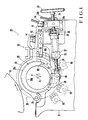
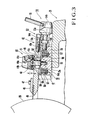
- Figs. 1 to 5 show a wiping apparatus for an intanglio printing press according to an embodiment of the present invention, in which:
- a feedboard 4 for receiving a sheet 1 fed one by one from the uppermost sheet by a sheet pick-up device of sheet feeder 2, and a swing pregripper 5 for gripping the sheet 1 on the feedboard 1 and aligning it are arranged between the sheet feeder 2 on which sheets 1 are stacked and a printing unit 3 located in front of the sheet feeder 2.
- three gripper units 8 each consisting of a gripper 6 and a gripper pad 7 are mounted at equal angular positions on the surface of an impression cylinder 9.
- a copperplate cylinder 10 having substantially the same diameter as that of the impression cylinder 9, a transfer cylinder 11 having a diameter substantially 1/3 that of the impression cylinder 9, and a delivery cylinder 12 having substantially the same diameter as that of the transfer cylinder 11 are in contact with the impression cylinder 9.
- the transfer cylinder 11 has one gripper unit as in the gripper unit 8 to transfer the sheet gripped from the swing pregripper 5 to the gripper unit 8 of the impression cylinder 9.
- a pair of right and left delivery chains 13 are looped between a sprocket (not shown) and a sprocket coaxial with the delivery cylinder 12. Delivery grippers are arranged along the delivery chains 13 to grip the sheet 1 from the gripper unit 8 of the impression cylinder 9 to convey the sheet 1 upon traveling of the delivery chains 13.
- a copperplate including a flat portion as a non-image portion and recesses constituting an image portion is mounted on the outer surface of the copperplate cylinder 10.
- a plurality of form rollers 14 are in contact with the surface of the copperplate.
- Duct rollers 16 rotated in ink fountains 15 are in contact with the corresponding form rollers 14.
- Reference numerals 17 denote vibrating rollers which are in contact with the corresponding duct rollers 16 to uniforming the thicknesses of films of an ink supplied from the ink fountains 15.
- the intanglio printing press having the above arrangement includes a wiping apparatus 20.
- the wiping apparatus 20 includes a cleaning solution tank 21 located obliquely below the copperplate cylinder 10 and supported on the press-side frame.
- a cleaning solution 22 such as TRICLEN (tradename) is stored in the cleaning solution tank 21.
- a pair of bearing covers 23 of a half-split hinge type pivotal about a shaft 22 are mounted on both side plates at the upper opening of the cleaning solution tank 21.
- the covers 23 are closed and fixed by a fastening metal piece 24.
- An eccentric bearing 25 is fixed by a split ring in each bearing cover 23 and is eccentric by a difference t between a metal axis F as the center of an outer surface 25a in Fig.
- a wiping roller 26 is rotatably supported and axially reciprocated so as to be in contact with a copperplate surface of the copperplate cylinder 10 such that both ends of the wiping roller 26 are inserted into the inner holes 25b of the eccentric bearings 25 through bushes 27 and rolling bearings 28, respectively.
- the wiping roller 26 is driven from a motor side by a gear 29 fixed to one end of the wiping roller 26 and a pinion 30 located therebelow and meshed therewith.
- the wiping roller 26 can be axially reciprocated by a swinging mechanism (not shown) obtained by fitting a roller on a slotted wheel 31 at the other end of the wiping roller 26.
- the rotational direction of the wiping roller 26 is the same as that of the copperplate cylinder 10, as indicated by arrows, so that the surfaces travel in opposite directions.
- Screw bearings 32 each having a screw hole are bolted at the upper ends of both the side plates of the cleaning solution tank 21.
- a screw shaft 34 with a handle 33 is rotatably inserted into the screw hole of each screw bearing 32.
- Reference numeral 35 denotes a thrust bearing 36 built-in coupling pivotally mounted on the distal end of each screw shaft 34.
- a hydraulic cylinder 37 is coaxial with the corresponding screw shaft 34 and fixed to the corresponding coupling 35.
- Each piston rod 38 is located immediately under the wiping roller 26.
- each piston rod 38 is pivotally fixed through a pin 40 to a metal piece 39 bolted to the corresponding eccentric bearing 25, so that the piston rods 38 of the hydraulic cylinders 37 can be reciprocated so as to pivot the eccentric bearings 25 about the metal axes F. Therefore, the wiping roller 26 can be brought into contact with the copperplate cylinder 10 or separated therefrom by an eccentric behavior.
- the handles 33 are rotated to reciprocate the screw shafts 34. Therefore, the contact pressure of the wiping roller 26 can be fine-adjusted with respect to the surface of the copperplate.
- Reference numeral 34a denotes a fixing nut with a handle 34b which fixes the corresponding screw shaft 34 at a desired angular position.
- An elongated blade base 41 having a rectangular cross section is supported on the upper surface of a rear side plate 21b of the cleaning solution tank 21 so as to be guided in a direction perpendicular to the axis upon engagement of three dovetailed guides 42, i.e., two end guides and one central guide.
- Reference numeral 43 denotes a blade holder having a larger width but a smaller length than those of the blade base 41.
- the blade holder 43 overlaps an inclined surface 41a formed except for both ends of the blade base 41 and is detachably fixed by four fixing screws 44 (to be described later).
- a doctor blade (to be referred to as a blade hereinafter) 45 of a plate-like elastic member made of synthetic rubber or the like is pressed by a blade press member 46 and is fixed by a plurality of bolts 47.
- Each fixing screw 44 comprises a head 44b with a plurality of handle insertion holes 44a, a pin portion 44c, and a male thread 44b threadably engaged in the corresponding screw hole of the slide base 41.
- a gap represented by reference symbol t1 in Fig. 3 is formed between the lower surface of the head 44b and the blade holder 43 at a limit position where the step between the pin portion 44c and the male thread 44d abuts against a fastening surface.
- a plurality of belleville springs 48 are clamped between caps 49 and washers 50 and are inserted in the gaps t1 of the respective fixing screws 44.
- Compression coil springs 51 are inserted in annular grooves of the heads 44b, respectively.
- Stoppers 52 are fitted on lower end portions of the pin portions 44c, respectively.
- Each fitting hole 43a for the pin portion 44c is a longitudinal hole having substantially the same width as that of the pin portion 44c. The stopper 52 abuts against an edge of the corresponding hole to prevent removal of the corresponding fixing screw 44.
- the blade holder 43 can be moved to come close to or to be separated from the wiping roller 26.
- Right and Left L-shaped blade holder moving metal pieces 53 are bolted at the right and left portions of the blade holder 43.
- Pin portions 54a of an adjusting handle 54 for adjusting the blade holder back and forth are respectively fitted in U-shaped grooves 53a of the vertical members of the metal pieces 53.
- the adjusting handle 54 comprises pin portions 54a, a head 54a with handle elements 55, a large-diameter portion 54c for regulating movement of the adjusting handle 54 together with the head 54b, and a male thread 54d threadably engaged with the corresponding screw hole formed in the blade base 41.
- the distal end of the blade 45 is in contact with the surface of the wiping roller 26 and wipes the cleaning solution which flows around the circumferential surface of the wiping roller 26.
- a pair of front and rear spring mechanisms 56 are arranged at the left and and right end portions of the blade base 41 to bias the blade holder 43 against the blade base 41.
- Each spring mechanism 56 comprises a compression coil spring 57 fitted in a stepped spring hole in the blade base 41, a vertically movable stepped cap 58 capped on the compression coil spring 57, and a rectangular cap press member 59 bolted on the bottom surface of a longitudinal hole portion of the spring hole. The cap 58 which is not removed from the spring hole by the cap press member 59 is biased by the compression coil spring 57, thereby biasing the blade holder 43 upward.
- the blade base 41 of the blade unit having the above arrangement is slightly reciprocally adjusted by the adjusting screws 54 and is reciprocated in synchronism with attachment/detachment of the wiping roller 26.
- Cams 60 having cam surfaces 60a which are not coaxial with the outer surfaces 25a and have arcuated grooves are bolted on the side surfaces of both the eccentric bearings 25, respectively.
- Cam levers 62 having free end portions which are pivotally mounted with cam followers 61 engaged with the cam surfaces 60a are bolted at both end portions of the blade base 41, respectively.
- the cam levers 62 are reciprocated back and forth while its vertical position is kept unchanged by the behavior of the outer surfaces 25a and the non-axial cam surfaces 60a. Therefore, the blade 45 is reciprocated.
- the blade 45 is separated from the wiping roller 26 accordingly.
- the wiping roller 26 is brought into contact with the copperplate cylinder, the blade 45 is also brought into contact with the wiping roller 26.
- the contact pressure of the blade 45 in the contact state is kept unchanged before and after separation. Therefore, the contact pressure need not be readjusted.
- the position of the metal axis F falls within an angular range around the wiping roller axis F1 symmetrical about an angle ⁇ defined by the copperplate cylinder axis F2, the wiping roller axis F1, and the pinion axis F3. More specifically, the position of the metal axis F falls within the range of ⁇ 45° with respect to a line perpendicular to a line connecting the wiping roller axis F1 and the copperplate cylinder axis F2.
- the position of the metal axis F falls within the range of ⁇ 45° with respect to a line extending from a line connecting the pinion axis F3 and the wiping roller F1.
- the gear 29 is negatively shifted so as not to interfere meshing of the gear upon pivotal movement of the eccentric bearing 25 and a change in axial distance between the gear 29 and the pinion 30. Even if the eccentric bearings 25 are pivoted, no problem occurs in meshing between the gear 29 and the pinion 30.
- reference numerals 63 denote a plurality of brushes, pad surfaces of which are supported by arms (not shown) so as to be brought into contact with the surface of the wiping roller 26.
- An ink transferred from the copperplate to the surface of the wiping roller 26 is removed into the cleaning solution tank 21 by a dissolution effect of the cleaning solution permeating into the pads and the urging pressure of the brushes 63.
- the sheet 1 fed one by one from the sheet feeder 2 to the feedboard 4 is gripped by the gripper unit 8 of the impression cylinder 9 through the swing pregripper 5 and the transfer cylinder 11.
- Inks of three colors in the ink fountains 15 are supplied by the form rollers 14 to the copperplate surface of the copperplate cylinder 10. These inks are transferred to the sheet 1 passing through the cylinders 9 and 10, thus performing printing.
- the printed sheet 1 is regripped by the grippers of the delivery chains 13 and is conveyed and discharged.
- a wiping operation during printing will be described below.
- the hydraulic cylinders 37 are operated in synchronism with the above operations.
- the retracted piston rods 38 are extended to the illustrated positions, and the eccentric bearings 25 are pivoted clockwise about the metal axes F.
- the wiping roller 26 is urged against the copperplate.
- the cams 60 are pivoted clockwise in the illustrated positions.
- the cam followers 61 are engaged with the cam surfaces 60a to move the cam levers 62 forward.
- the blade base 41 integrally coupled to the cam levers 62 is moved parallel along the guides 42.
- the distal end of the blade 45 is brought into contact with the wiping roller 26.
- an excessive ink applied by the form rollers 14 to the portions around the recesses serving as the picture pattern of the copperplate surface is wiped by the wiping roller 26 and is transferred to the surface of the wiping roller 26.
- the transferred ink is removed into the cleaning solution tank by the cleaning behavior of the cleaning solution permeating into the pads of the brushes 63 and the pressure of the brushes 63.
- the cleaning solution flowing around the surface of the wiping roller 26 is removed by the blade 45 into the cleaning solution tank 21.
- the fixing nuts 34a are loosened and the handles 33 are rotated to reciprocate the screw shafts 34.
- the hydraulic cylinders 37 connected to the screw shafts 34 through couplings 36 are reciprocated to slightly pivot the eccentric bearings 25 in the same manner as described above. Therefore, the contact pressure of the wiping roller 26 can be fine-adjusted. This adjustment can be performed while wiping during printing is checked.
- the handle elements 55 are held to pivot the adjusting screws 54, the blade holder 43 is reciprocated and the blade 45 integrally formed therewith is also reciprocated. Therefore, the contact pressure of the blade 45 can be adjusted.
- the screws corresponding to the fixing screws 44 are loosened to move the blade base 41.
- the blade base 41 is urged against the blade base 41 by the elastic forces of the belleville springs 48. Therefore, the blade 45 can be adjusted while the fixing screws 44 are kept fastened.
- the wiping roller 26 and the blade 45 are synchronously operated and are brought into contact with each other.
- the relative position between the blade holder 43 and the blade base 41 is not changed.
- the contact pressure of the blade 45 is the same as that prior to the interruption of printing.
- the blade 45 is separated from the wiping roller due to positional setting of the metal axis F and the shape of the cam surfaces 60a.
- the wiping roller 26 then follows the blade 45.
- the distal end of the blade 45 is not interfered with the surface of the wiping roller 26.
- the position of the metal axis F is properly set, and a meshing depth between the gear 29 and the pinion 30 is not increased or decreased so as to interfere the operation.
- the blade holder 43 When the pads of the brushes 63 are worn and a hand is inserted into the brush from the upper direction, or when the blade 45 is worn, the blade holder 43 is removed.
- the handle When the handle is inserted into the handle hole 44a of each fixing screw 44 to loosen it, the corresponding male thread 44d is removed from the screw hole, the elastic force of the corresponding belleville spring is released, and the elastic force of the corresponding coil spring 57 acts on the lower surface of the blade holder 43.
- the elastic force is balanced with the weight of the remaining portion of the blade holder 43, so that the blade holder 43 is moved upward horizontally or in an inclined state wherein the blade 45 side of the holder 43 is higher than the opposite side thereof.
- the distal end of the blade 45 is not brought into contact with the surface of the wiping roller 26.
- the corresponding stopper 52 is urged against the longitudinal hole 43a by the elastic force of the corresponding compression coil spring 51. Therefore, the blade holder 43 are removed together with the fixing screws 44.
- the blade holder 43 When a replacement operation or the like is completed and the blade holder 43 is attached again, the blade holder 43 is placed on the blade base 41, and the handle is inserted into each handle hole 44a to engage the male thread 44d of the fixing screw 44 with the corresponding screw hole.
- the corresponding compression coil spring 51 is compressed, and the fixing screw 44 is threadably engaged such that the step of the pin portion 44c of this fixing screw 44 abuts against the stepped portion of the screw hole while the elastic force is accumulated by the corresponding belleville spring 48.
- the blade holder 43 is reciprocally supported by guiding the longitudinal holes 43a by the pin portions 44c.
- the piston rod actuating ends of the fluid pressure cylinders are pivotally supported by the eccentric bearings for supporting the wiping roller.
- the fluid pressure cylinders are supported by the fine-adjusting mechanism in the reciprocal direction of each piston rod.
- the wiping roller is separated from the copperplate cylinder by the fluid pressure cylinders.
- the wiping roller is brought into contact with the copperplate cylinder by the stroke limit of each fluid pressure cylinder. In this manner, the contact pressure of the wiping roller prior to the interruption of printing can be kept unchanged.
- the contact pressure need not be adjusted to reduce labor, and the interruption time can be shorted to improve productivity.
- the fluid pressure cylinders can be easily automated, and attachment/detachment of the wiping roller is interlocked with that of the printing cylinder. In this manner, a skilled person for attachment/detachment of the wiping roller is not required to achieve energy saving.
- the contact pressure of the wiping roller can be adjusted independently of attachment/detachment thereof during the operation of the printing press. In other words, contact pressure adjustment of the wiping roller can be performed while wiping is being checked, thus improving the wiping function.
- the holding member for holding the doctor blade and the press-side support member are coupled by the plurality of fixing screws.
- the support member is reciprocally supported relative to the press side in an attachment/detachment direction of the doctor blade.
- the wiping roller eccentric bearings and the doctor blade support member are coupled by cam mechanisms for interlocking pivotal movement of the eccentric bearings with reciprocal movement of the support member.
- the doctor blade contact pressure fine-adjusting mechanism is arranged to reciprocate the holding member relative to the support member.
- the eccentric bearings are pivoted at the time of interruption of printing and at the time of restarting of printing to separate the wiping roller from the copperplate cylinder and bring the wiping roller into contact with the copperplate cylinder.
- the doctor blade is separated from the wiping roller through the cam mechanisms and brought into contact therewith in synchronism with the operation between the wiping roller and the copperplate cylinder, thereby improving operability, facilitating automation, and hence achieving energy saving.
- the relative position between the blade holding member and the press-side support member is kept unchanged, and the contact pressure of the doctor blade is also kept unchanged. The contact pressure need not be readjusted at the time of restarting of printing. Therefore, the interruption time can be shortened and productivity can be improved.
- the distal end of the doctor blade is not brought into contact with the surface of the wiping roller when the doctor blade is removed.
- the surface of the wiping roller is not damaged to improve durability.
- the shape of the cam surface is properly determined, so that the blade is not urged in the initial period of removal of the wiping roller and the blade can be slightly separated from the surface of the wiping roller at the end of removal. Therefore, damage to the surface of the wiping roller by impact caused by backlash during rotation, starting, and stopping of the roller can be prevented.
- the relative position between the holding member and the support member can be adjusted. Wiping roller deterioration over time can be easily compensated, thus improving the function of the wiping apparatus.
- the spring members are fitted in spring holes formed in the support member surface opposite to the holding member to bias the holding member so as to separate it from the support member.
- the holding member In order to remove the doctor blade, when the fixing screws are loosened, the holding member is moved upward by the elastic forces of the spring members and the doctor blade is separated from the surface of the wiping roller. Therefore, damage to the surface of the wiping roller can be prevented.
- each belleville spring is inserted between the flat surface of the holding member and the corresponding head of the fixing screw for fixing the doctor blade holding member to the press-side support member.
- Each compression coil spring having a lower spring constant than the corresponding belleville spring is inserted between this belleville spring and the corresponding head of the fixing screw.
- each fixing screw removal preventive stopper is fitted on the corresponding fixing screw.
- the doctor blade contact pressure fine-adjusting unit is arranged between the holding member and the support member to reciprocate the holding member. When the contact pressure fine-adjusting unit is operated, the holding member is slid and moved between the belleville springs and the support member.
- the contact pressure of the doctor blade with respect to the wiping roller can be adjusted without loosening the fixing screws.
- operability of the wiping apparatus can be improved.
- the contact pressure of the doctor blade can be adjusted without loosening the fixing screws, and readjustment of the contact pressure is not required.
- the interruption time can be shortened, and productivity can be improved.
- the fixing screws are fully loosened, the fixing screws are biased by the compression coil springs but cannot be independently removed by the stoppers. The fixing screws are therefore removed together with the holding member. The fixing screws will not be lost.
- the compression coil springs and then the belleville springs are compressed. The screws can be easily threadably engaged with the screw holes, thus improving operability.
- the belleville spring produces a large spring force by fastening.
- a hydraulic cylinder is used as the fluid pressure cylinder.
- an air cylinder may be used in place of the hydraulic cylinder.
- the adjusting mechanism which supports the fluid pressure cylinder to fine-adjust the piston rod in the reciprocal direction is not limited to the arrangement exemplified in the above embodiment.
Landscapes
- Engineering & Computer Science (AREA)
- Mechanical Engineering (AREA)
- Rotary Presses (AREA)
Priority Applications (4)
| Application Number | Priority Date | Filing Date | Title |
|---|---|---|---|
| EP88114700A EP0357825B2 (fr) | 1988-09-08 | 1988-09-08 | Dispositiv de raclage pour machine d'impression en héliogravure |
| US07/241,577 US4899654A (en) | 1988-09-08 | 1988-09-08 | Wiping apparatus for intaglio printing press |
| DE3886399T DE3886399T3 (de) | 1988-09-08 | 1988-09-08 | Rakelvorrichtung für Tiefdruckmaschinen. |
| AT88114700T ATE98557T1 (de) | 1988-09-08 | 1988-09-08 | Rakelvorrichtung fuer tiefdruckmaschinen. |
Applications Claiming Priority (1)
| Application Number | Priority Date | Filing Date | Title |
|---|---|---|---|
| EP88114700A EP0357825B2 (fr) | 1988-09-08 | 1988-09-08 | Dispositiv de raclage pour machine d'impression en héliogravure |
Publications (3)
| Publication Number | Publication Date |
|---|---|
| EP0357825A1 true EP0357825A1 (fr) | 1990-03-14 |
| EP0357825B1 EP0357825B1 (fr) | 1993-12-15 |
| EP0357825B2 EP0357825B2 (fr) | 2002-01-09 |
Family
ID=8199286
Family Applications (1)
| Application Number | Title | Priority Date | Filing Date |
|---|---|---|---|
| EP88114700A Expired - Lifetime EP0357825B2 (fr) | 1988-09-08 | 1988-09-08 | Dispositiv de raclage pour machine d'impression en héliogravure |
Country Status (4)
| Country | Link |
|---|---|
| US (1) | US4899654A (fr) |
| EP (1) | EP0357825B2 (fr) |
| AT (1) | ATE98557T1 (fr) |
| DE (1) | DE3886399T3 (fr) |
Cited By (5)
| Publication number | Priority date | Publication date | Assignee | Title |
|---|---|---|---|---|
| EP0475890A1 (fr) * | 1990-08-17 | 1992-03-18 | De La Rue Giori S.A. | Dispositif d'essuyage pour le cylindre de plaque d'une machine d'impression en creux |
| DE4213660A1 (de) * | 1992-04-25 | 1993-11-11 | Koenig & Bauer Ag | Rakelbalken für ein Kurzfarbwerk |
| US5345866A (en) * | 1992-04-25 | 1994-09-13 | Koenig & Bauer Aktiengesellschaft | Doctor blade bar assembly |
| EP0765745A1 (fr) * | 1995-09-27 | 1997-04-02 | Komori Corporation | Dispositif de raclage pour une machine d'impression en creux |
| CN104385773A (zh) * | 2014-11-24 | 2015-03-04 | 松德机械股份有限公司 | 一种印刷机刮刀装置 |
Families Citing this family (10)
| Publication number | Priority date | Publication date | Assignee | Title |
|---|---|---|---|---|
| US5088407A (en) * | 1990-04-25 | 1992-02-18 | F. L. Smithe Machine Company, Inc. | Rotary printer for an envelope machine |
| CA2073118C (fr) * | 1991-07-30 | 2004-09-14 | Ernst Anton Blass | Machine d'heliogravure |
| US5423259A (en) * | 1994-09-12 | 1995-06-13 | Su; Wu-Shuan | Apparatus for erasing a plate cylinder of an offset printing press |
| EP1844930A1 (fr) * | 2006-04-11 | 2007-10-17 | Kba-Giori S.A. | Dispositif d'essuyage de l'encre pour une machine d'impression |
| US8281717B2 (en) * | 2007-07-25 | 2012-10-09 | Air Motion Systems, Inc. | Printing cylinder cleaning system |
| CN105150668A (zh) * | 2010-06-04 | 2015-12-16 | 小森公司 | 印刷机的接触压力调整方法和接触压力调整装置 |
| EP2636527A1 (fr) * | 2012-03-09 | 2013-09-11 | Kba-Notasys Sa | Système d'essuyage d'encre d'une presse d'impression en creux et presse d'impression en creux le comprenant |
| CN103331990B (zh) * | 2013-07-16 | 2014-12-17 | 大理美登印务有限公司 | 一种凹印机改进型刮墨刀锁紧调节装置 |
| JP6399647B2 (ja) * | 2014-09-17 | 2018-10-03 | 株式会社小森コーポレーション | 凹版印刷機のワイピング・ローラの接触圧調整方法及び装置 |
| JP6399648B2 (ja) * | 2014-09-17 | 2018-10-03 | 株式会社小森コーポレーション | 凹版印刷機のワイピング・ローラの接触圧調整方法及び装置 |
Citations (3)
| Publication number | Priority date | Publication date | Assignee | Title |
|---|---|---|---|---|
| GB282381A (en) * | 1926-12-18 | 1928-05-24 | Maschf Augsburg Nuernberg Ag | Improvements in rotary intaglio printing multi-machines |
| FR855679A (fr) * | 1939-01-31 | 1940-05-17 | Perfectionnements aux machines à imprimer par héliogravure | |
| GB1126097A (en) * | 1965-10-09 | 1968-09-05 | Maschf Augsburg Nuernberg Ag | Improvements in or relating to rotary printing machines |
Family Cites Families (6)
| Publication number | Priority date | Publication date | Assignee | Title |
|---|---|---|---|---|
| US2987993A (en) * | 1956-08-24 | 1961-06-13 | Giori Gualtiero | Ink regulating device for intaglio and similar printing machines |
| US3762319A (en) * | 1971-08-20 | 1973-10-02 | American Bank Note Co | Plate wiping mechanism for intaglio press |
| US4290361A (en) * | 1980-01-11 | 1981-09-22 | American Newspaper Publishers Association | On the fly adjusting mechanism for rotary printing presses |
| DE3112745C2 (de) * | 1981-03-31 | 1988-05-05 | M.A.N.- Roland Druckmaschinen AG, 6050 Offenbach | An einen Plattenzylinder einer Offset- oder Hochdruckmaschine anstellbarer Walzenstock |
| JPS58101060A (ja) * | 1981-12-12 | 1983-06-16 | Komori Printing Mach Co Ltd | 凹版印刷機のワイピング装置 |
| US4676157A (en) * | 1985-05-28 | 1987-06-30 | Komori Printing | Wiping apparatus for intaglio printing machine |
-
1988
- 1988-09-08 DE DE3886399T patent/DE3886399T3/de not_active Expired - Lifetime
- 1988-09-08 AT AT88114700T patent/ATE98557T1/de not_active IP Right Cessation
- 1988-09-08 EP EP88114700A patent/EP0357825B2/fr not_active Expired - Lifetime
- 1988-09-08 US US07/241,577 patent/US4899654A/en not_active Expired - Lifetime
Patent Citations (3)
| Publication number | Priority date | Publication date | Assignee | Title |
|---|---|---|---|---|
| GB282381A (en) * | 1926-12-18 | 1928-05-24 | Maschf Augsburg Nuernberg Ag | Improvements in rotary intaglio printing multi-machines |
| FR855679A (fr) * | 1939-01-31 | 1940-05-17 | Perfectionnements aux machines à imprimer par héliogravure | |
| GB1126097A (en) * | 1965-10-09 | 1968-09-05 | Maschf Augsburg Nuernberg Ag | Improvements in or relating to rotary printing machines |
Cited By (10)
| Publication number | Priority date | Publication date | Assignee | Title |
|---|---|---|---|---|
| EP0475890A1 (fr) * | 1990-08-17 | 1992-03-18 | De La Rue Giori S.A. | Dispositif d'essuyage pour le cylindre de plaque d'une machine d'impression en creux |
| CH681875A5 (fr) * | 1990-08-17 | 1993-06-15 | De La Rue Giori Sa | |
| CN1049862C (zh) * | 1990-08-17 | 2000-03-01 | 乔里路公司 | 凹版印刷机印版滚筒的擦拭装置 |
| DE4213660A1 (de) * | 1992-04-25 | 1993-11-11 | Koenig & Bauer Ag | Rakelbalken für ein Kurzfarbwerk |
| US5345866A (en) * | 1992-04-25 | 1994-09-13 | Koenig & Bauer Aktiengesellschaft | Doctor blade bar assembly |
| US5345867A (en) * | 1992-04-25 | 1994-09-13 | Koenig & Bauer Aktiengesellschaft | Doctor blade bar assembly |
| EP0765745A1 (fr) * | 1995-09-27 | 1997-04-02 | Komori Corporation | Dispositif de raclage pour une machine d'impression en creux |
| US5765480A (en) * | 1995-09-27 | 1998-06-16 | Komori Corporation | Wiping device of intaglio printing press |
| CN104385773A (zh) * | 2014-11-24 | 2015-03-04 | 松德机械股份有限公司 | 一种印刷机刮刀装置 |
| CN104385773B (zh) * | 2014-11-24 | 2017-03-15 | 松德机械股份有限公司 | 一种印刷机刮刀装置 |
Also Published As
| Publication number | Publication date |
|---|---|
| DE3886399T2 (de) | 1994-04-07 |
| EP0357825B2 (fr) | 2002-01-09 |
| ATE98557T1 (de) | 1994-01-15 |
| DE3886399T3 (de) | 2002-07-04 |
| DE3886399D1 (de) | 1994-01-27 |
| US4899654A (en) | 1990-02-13 |
| EP0357825B1 (fr) | 1993-12-15 |
Similar Documents
| Publication | Publication Date | Title |
|---|---|---|
| US4899654A (en) | Wiping apparatus for intaglio printing press | |
| EP1724115B1 (fr) | Dispositif d'encrage | |
| JP2007007881A (ja) | 印刷機のインキ装置 | |
| EP0769376A1 (fr) | Machine d'impression de feuilles | |
| US4960049A (en) | Offset printing machine having two printing units | |
| US4138944A (en) | Print module | |
| US5590598A (en) | Horizontal sheet transfer multiple color offset rotary printing press with horizontal slide access | |
| JPH0717049B2 (ja) | オフセット印刷機におけるローラの接続・分離装置 | |
| DE10315193A1 (de) | Gegendruckzylinder in einer Wendeeinrichtung einer bogenverarbeitenden Maschine | |
| EP0275025B1 (fr) | Dispositif d'encrage pour machine à imprimer | |
| US6490972B1 (en) | Offset printer having mechanism for moving ink rollers into contact with and out of contact from plate cylinder | |
| JP4904018B2 (ja) | 刷版搬送のための方法及び装置 | |
| JPH0747305B2 (ja) | 凹版印刷機のワイピング装置 | |
| US5046422A (en) | Ink removing system for an offset printing machine | |
| EP0895859B1 (fr) | Dispositif élévateur pour des rouleaux toucheur-encreur dans une machine à imprimer | |
| JPH0747306B2 (ja) | 凹版印刷機のワイピング装置 | |
| JP3421485B2 (ja) | 凹版印刷機のワイピング装置 | |
| DE102020120997A1 (de) | Verfahren zum Betreiben eines Druckwerks einer Druckmaschine sowie Druckwerk | |
| JPH0798390B2 (ja) | 凹版印刷機のワイピング装置 | |
| DE1159471B (de) | Vorrichtung zum Einstellen auf unterschiedliche Bogenstaerken bei einer Rotationsbogendruckmaschine fuer Mehrfarbendruck | |
| DE310968C (fr) | ||
| JP2531467Y2 (ja) | 印刷機のショック防止装置 | |
| DE9205400U1 (de) | Vorrichtung zum Ausrichten von Bogen | |
| JPH0723547U (ja) | 小型オフセット印刷機 | |
| JP5851747B2 (ja) | ゴミ取り装置 |
Legal Events
| Date | Code | Title | Description |
|---|---|---|---|
| PUAI | Public reference made under article 153(3) epc to a published international application that has entered the european phase |
Free format text: ORIGINAL CODE: 0009012 |
|
| AK | Designated contracting states |
Kind code of ref document: A1 Designated state(s): AT CH DE FR GB IT LI SE |
|
| 17P | Request for examination filed |
Effective date: 19900308 |
|
| RAP1 | Party data changed (applicant data changed or rights of an application transferred) |
Owner name: KOMORI CORPORATION |
|
| 17Q | First examination report despatched |
Effective date: 19910926 |
|
| GRAA | (expected) grant |
Free format text: ORIGINAL CODE: 0009210 |
|
| AK | Designated contracting states |
Kind code of ref document: B1 Designated state(s): AT CH DE FR GB IT LI SE |
|
| REF | Corresponds to: |
Ref document number: 98557 Country of ref document: AT Date of ref document: 19940115 Kind code of ref document: T |
|
| REF | Corresponds to: |
Ref document number: 3886399 Country of ref document: DE Date of ref document: 19940127 |
|
| ITF | It: translation for a ep patent filed | ||
| ET | Fr: translation filed | ||
| PLBI | Opposition filed |
Free format text: ORIGINAL CODE: 0009260 |
|
| 26 | Opposition filed |
Opponent name: DE LA RUE GIORI S.A. Effective date: 19940913 |
|
| EAL | Se: european patent in force in sweden |
Ref document number: 88114700.3 |
|
| PLAW | Interlocutory decision in opposition |
Free format text: ORIGINAL CODE: EPIDOS IDOP |
|
| APAC | Appeal dossier modified |
Free format text: ORIGINAL CODE: EPIDOS NOAPO |
|
| APAE | Appeal reference modified |
Free format text: ORIGINAL CODE: EPIDOS REFNO |
|
| APAC | Appeal dossier modified |
Free format text: ORIGINAL CODE: EPIDOS NOAPO |
|
| APCC | Communication from the board of appeal sent |
Free format text: ORIGINAL CODE: EPIDOS OBAPO |
|
| APCC | Communication from the board of appeal sent |
Free format text: ORIGINAL CODE: EPIDOS OBAPO |
|
| APCC | Communication from the board of appeal sent |
Free format text: ORIGINAL CODE: EPIDOS OBAPO |
|
| APAC | Appeal dossier modified |
Free format text: ORIGINAL CODE: EPIDOS NOAPO |
|
| PLAW | Interlocutory decision in opposition |
Free format text: ORIGINAL CODE: EPIDOS IDOP |
|
| PUAH | Patent maintained in amended form |
Free format text: ORIGINAL CODE: 0009272 |
|
| STAA | Information on the status of an ep patent application or granted ep patent |
Free format text: STATUS: PATENT MAINTAINED AS AMENDED |
|
| REG | Reference to a national code |
Ref country code: GB Ref legal event code: IF02 |
|
| 27A | Patent maintained in amended form |
Effective date: 20020109 |
|
| AK | Designated contracting states |
Kind code of ref document: B2 Designated state(s): AT CH DE FR GB IT LI SE |
|
| REG | Reference to a national code |
Ref country code: CH Ref legal event code: AEN Free format text: AUFRECHTERHALTUNG DES PATENTES IN GEAENDERTER FORM |
|
| ET3 | Fr: translation filed ** decision concerning opposition | ||
| APAH | Appeal reference modified |
Free format text: ORIGINAL CODE: EPIDOSCREFNO |
|
| PGFP | Annual fee paid to national office [announced via postgrant information from national office to epo] |
Ref country code: DE Payment date: 20070906 Year of fee payment: 20 |
|
| PGFP | Annual fee paid to national office [announced via postgrant information from national office to epo] |
Ref country code: AT Payment date: 20070912 Year of fee payment: 20 Ref country code: CH Payment date: 20070913 Year of fee payment: 20 |
|
| PGFP | Annual fee paid to national office [announced via postgrant information from national office to epo] |
Ref country code: GB Payment date: 20070905 Year of fee payment: 20 |
|
| PGFP | Annual fee paid to national office [announced via postgrant information from national office to epo] |
Ref country code: SE Payment date: 20070905 Year of fee payment: 20 Ref country code: IT Payment date: 20070926 Year of fee payment: 20 |
|
| PGFP | Annual fee paid to national office [announced via postgrant information from national office to epo] |
Ref country code: FR Payment date: 20070914 Year of fee payment: 20 |
|
| REG | Reference to a national code |
Ref country code: CH Ref legal event code: PL |
|
| REG | Reference to a national code |
Ref country code: GB Ref legal event code: PE20 Expiry date: 20080907 |
|
| EUG | Se: european patent has lapsed | ||
| PG25 | Lapsed in a contracting state [announced via postgrant information from national office to epo] |
Ref country code: GB Free format text: LAPSE BECAUSE OF EXPIRATION OF PROTECTION Effective date: 20080907 |