EP0356635A2 - Dispositif d'évacuation - Google Patents
Dispositif d'évacuation Download PDFInfo
- Publication number
- EP0356635A2 EP0356635A2 EP89110633A EP89110633A EP0356635A2 EP 0356635 A2 EP0356635 A2 EP 0356635A2 EP 89110633 A EP89110633 A EP 89110633A EP 89110633 A EP89110633 A EP 89110633A EP 0356635 A2 EP0356635 A2 EP 0356635A2
- Authority
- EP
- European Patent Office
- Prior art keywords
- housing
- powder
- cyclone
- outlet opening
- conveyor
- Prior art date
- Legal status (The legal status is an assumption and is not a legal conclusion. Google has not performed a legal analysis and makes no representation as to the accuracy of the status listed.)
- Withdrawn
Links
Images


Classifications
-
- B—PERFORMING OPERATIONS; TRANSPORTING
- B05—SPRAYING OR ATOMISING IN GENERAL; APPLYING FLUENT MATERIALS TO SURFACES, IN GENERAL
- B05B—SPRAYING APPARATUS; ATOMISING APPARATUS; NOZZLES
- B05B7/00—Spraying apparatus for discharge of liquids or other fluent materials from two or more sources, e.g. of liquid and air, of powder and gas
- B05B7/14—Spraying apparatus for discharge of liquids or other fluent materials from two or more sources, e.g. of liquid and air, of powder and gas designed for spraying particulate materials
- B05B7/1404—Arrangements for supplying particulate material
- B05B7/144—Arrangements for supplying particulate material the means for supplying particulate material comprising moving mechanical means
-
- B—PERFORMING OPERATIONS; TRANSPORTING
- B04—CENTRIFUGAL APPARATUS OR MACHINES FOR CARRYING-OUT PHYSICAL OR CHEMICAL PROCESSES
- B04C—APPARATUS USING FREE VORTEX FLOW, e.g. CYCLONES
- B04C5/00—Apparatus in which the axial direction of the vortex is reversed
- B04C5/14—Construction of the underflow ducting; Apex constructions; Discharge arrangements ; discharge through sidewall provided with a few slits or perforations
-
- B—PERFORMING OPERATIONS; TRANSPORTING
- B65—CONVEYING; PACKING; STORING; HANDLING THIN OR FILAMENTARY MATERIAL
- B65G—TRANSPORT OR STORAGE DEVICES, e.g. CONVEYORS FOR LOADING OR TIPPING, SHOP CONVEYOR SYSTEMS OR PNEUMATIC TUBE CONVEYORS
- B65G65/00—Loading or unloading
- B65G65/30—Methods or devices for filling or emptying bunkers, hoppers, tanks, or like containers, of interest apart from their use in particular chemical or physical processes or their application in particular machines, e.g. not covered by a single other subclass
- B65G65/34—Emptying devices
- B65G65/40—Devices for emptying otherwise than from the top
- B65G65/42—Devices for emptying otherwise than from the top using belt or chain conveyors
-
- B—PERFORMING OPERATIONS; TRANSPORTING
- B65—CONVEYING; PACKING; STORING; HANDLING THIN OR FILAMENTARY MATERIAL
- B65G—TRANSPORT OR STORAGE DEVICES, e.g. CONVEYORS FOR LOADING OR TIPPING, SHOP CONVEYOR SYSTEMS OR PNEUMATIC TUBE CONVEYORS
- B65G65/00—Loading or unloading
- B65G65/30—Methods or devices for filling or emptying bunkers, hoppers, tanks, or like containers, of interest apart from their use in particular chemical or physical processes or their application in particular machines, e.g. not covered by a single other subclass
- B65G65/34—Emptying devices
- B65G65/40—Devices for emptying otherwise than from the top
- B65G65/44—Devices for emptying otherwise than from the top using reciprocating conveyors, e.g. jigging conveyors
Definitions
- the invention relates to a discharge device for discharging essentially powdery material, in particular from cyclones, in which powdery material is recovered from powder coating systems.
- the excess powder is sucked out of the booths and reused.
- the powder-air mixture is passed from the cabins into one or more cyclones, in which the powder is separated and sinks down, where it e.g. is carried into a mobile container, a so-called powder trolley.
- cyclones alternately, i.e. e.g. two cyclones (or cyclone groups) are connected to a powder coating booth, in which case one cyclone (or one cyclone group) sucks the excess powder out of the booth, while the other cyclone (or the other cyclone group) sucks in the powder that is in the lower area of the Cyclones has accumulated, is discharged from this.
- the suction is interrupted, e.g. by separating the intake duct from the intake fan by means of a flap.
- the invention is therefore based on the object of designing a discharge device of the type mentioned in such a way that as little external air as possible can flow back into the cyclone when the powder is discharged.
- the discharge device flanged to the discharge end of the cyclone has a conveying device provided with at least one receiving chamber, which can be moved back and forth from a receiving position below the discharge end of the cyclone into a discharge position in which the absorbed powder is discharged is.
- the conveyor is expediently movably mounted in a housing which has an inlet opening and an outlet opening.
- the conveying device is preferably a piston which can be pushed back and forth in a guide tube and which is provided with a through-bore transverse to its longitudinal axis, the outlet opening being arranged axially offset from the inlet opening and the through-bore being displaceable under the inlet opening and over the outlet opening and back.
- the outlet opening is suitably substantially 180 o offset in the circumferential direction to face the inlet port.
- the conveying device is designed in the form of a roller which is rotatably mounted in the housing about an essentially horizontal axis, the outlet opening being circumferential direction is arranged offset to the inlet opening.
- the receiving chamber for the dissipated powder can in this case in the form of a blind bore transversely be formed to the axis of the roll, or it may have the form of a through bore, the receiving chamber which is divided by a partition into two sub-chambers, which then o offset in the circumferential direction by 180 to each other are.
- the blind bore or the two partial chambers can then be rotated from a receiving position below the outlet opening of the cyclone into a delivery position in which the powder is discharged and back.
- the outlet port can in the housing by about 135-180 o offset be formed to the inlet port.
- the conveying device is designed in the form of a ball rotatably mounted in the housing about an essentially horizontal axis, which is provided with a blind hole which can be rotated from a receiving position under the inlet opening of the housing into a delivery position above the outlet opening of the housing is.
- the outlet opening is in this case advantageously offset by approximately 180 o arranged substantially to the inlet port.
- the conveying device for example the roller or the ball, is provided on its periphery with a plurality of receiving chambers in the form of blind bores for the powder to be discharged.
- the conveyor can also be designed in the form of a toothed belt. These blind bores lie in a transverse plane of the conveyor and have the same angular spacings in the circumferential direction.
- Suitable seals in particular O-ring seals, are installed between the respective conveyor device and the housing.
- the conveying devices can be actuated periodically or continuously, in particular the conveying devices designed as a roller, ball or toothed belt can possibly rotate continuously.
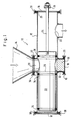
- the discharge device 10 has a housing 12 which here has the shape of a cylindrical guide tube which is flanged to the discharge end of a cyclone 14, e.g. by means of a quick-action lock 16.
- the longitudinal axis of the guide tube runs practically transverse to the longitudinal axis of the cyclone and generally horizontally.
- the end of the guide tube is closed by a respective closure cap 18, which can also be connected to the guide tube by quick-release fasteners 16, a seal 20, e.g. a flat gasket is inserted.
- a piston 22 is arranged so that it can be pushed axially back and forth.
- a piston rod 24 is firmly but easily detachably connected, for example screwed, through a corresponding opening in the right closure part 18 is guided outwards.
- the piston 22 can be moved back and forth in the housing 12 by means of a pneumatic cylinder (not shown).
- a pneumatic cylinder can, for example, be attached directly to the housing 12, in which case its longitudinal axis runs parallel to the longitudinal axis of the housing 12 and its piston or its piston rod can be firmly connected to the piston rod 24, for example by means of a carrier or a bracket 38.
- the piston 22 is provided with a through hole 26 and the housing 12 has an inlet port 28 and an axially for this staggered outlet port 30.
- the outlet port 30 is also offset relative to the inlet opening 28 in the circumferential direction by 180 o.
- the housing 12 can also, as shown, have a connection opening 32 opposite the inlet opening 28, which is also closed by a closure cover 18 with a quick-action closure 16.
- connection opening 32 In order to prevent powder from falling into the connection opening 32, an insert or a plug 36 is inserted into the connection opening 32, which is flush at its upper end with the inner wall of the guide tube 12.
- sealing rings e.g. O-rings, inserted in corresponding ring grooves in the piston 22, which seal the piston against the housing 12.
- O-rings e.g. Lip rings
- the inlet opening 28 of the housing 12 lies immediately below the outlet opening of the cyclone 14.
- the through bore 26 of the piston is also located directly below the outlet of the cyclone 14 (and the inlet opening of the housing 12). so that powder that accumulates in the lower end of the cyclone 14 falls into the through hole 26 and fills it up successively.
- the piston 22 is moved to the right in FIG. 1 by means of the pneumatic cylinder (not shown) until the through bore 26 comes to rest on the outlet opening 30, whereupon the powder from the bore 26 follows can fall down through the outlet opening 30, for example into a powder trolley.
- the stroke of the piston 22 thus corresponds to the axial distance between the two central axes of the inlet opening 28 and outlet opening 30. If the bore 26 is emptied, the piston 22 is moved back into its filling position shown in FIG. 1 and the whole process begins again.
- the piston can be reciprocated periodically, e.g. whenever the bore 26 is filled with powder or continuously, i.e. regardless of whether this bore 26 is completely filled.
- a vent or ventilation opening can expediently be provided in the left cover 18 in order to avoid the formation of an air cushion between the cover 18 and the end wall of the piston 22.
- the device shown in Fig. 1 enables the powdery material accumulating in the cyclone 14 to be discharged from the cyclone without the suction being interrupted since there is no connection between the outlet opening 30 of the housing 12 and the outlet opening of the cyclone 14. Therefore, no extraneous air can enter the cyclone 14 from the outlet opening 30. Only the small amount of air that is in the blind bore 26 of the piston 22 after the powder has been emptied through the outlet opening 30 and the piston has been returned to its starting position according to FIG. 1 can penetrate into the cyclone 14. This amount of air is very small in relation to the volume of the cyclone 14, because the piston 22 can for example have a diameter of 100 mm and Through hole 26 can have a diameter of 60 mm, for example.
- the outer diameter of the piston 22 is shown to be smaller than the inner diameter of the guide tube 12, but in practice the difference in diameter is considerably smaller, i.e. the piston runs practically with a sliding fit in the guide tube. Provision is also made that the piston 22 cannot rotate about its longitudinal axis during operation, for example by means of a square connection between the piston rod 24 and the plate 38.
- the length of the piston 22 is chosen such that even when the through-bore is in motion 26 of the piston 22 is located above the outlet opening 30 of the housing 12, the inlet opening 28 of the housing 12 and thus the outlet opening of the cyclone 14 aligned therewith is closed or blocked by the part of the piston 22 on the left in the figure, so that during the piston piston no powder can escape from the cyclone.
- the device shown in Fig. 1 has a very low height, it is easy to clean and blow out, since only the cover 18 has to be removed, after which the piston can be pulled out completely.
- the cover 18 closing the connection opening 32 can also be removed and from there the device can be cleaned and blown out.
- cyclones or several discharge devices according to FIG. 1 can be combined, for example in such a way that four cyclones are set up in a square and the pistons 22 are conveyed to a common center, so that the powdery material to be discharged from the cyclones is placed in a common powder container or powder truck can be removed.
- Fig. 2 shows a further embodiment of the invention, in which the discharge device has a roller 40 which is rotatably mounted in the housing 12 or the closure caps 18.
- the roller 40 is for this purpose Bearing pin 42 provided, one of which is guided through the corresponding cover 18 to the outside and is coupled to a drive device, for example a suitable motor.
- the roller 40 like the piston 22 according to FIG. 1, is provided with a receiving chamber for receiving the powdery material that accumulates in the lower end of the cyclone 14.
- FIG. 2 shows two embodiments of such a receiving chamber.
- the roller 40 is provided with a blind bore 44 which runs from top to bottom in FIG. 2 and whose lower end is delimited by a bottom or a wall 50 of the roller 40.
- the intermediate wall 46 shown in FIG. 2 is not present.
- the roller 40 is provided with a through hole which is divided in the middle by the intermediate wall 46 into two partial chambers or partial holes 48.
- the housing is, as in Fig. 1, provided with an inlet opening 28, which is immediately below the outlet opening of the cyclone 14, and with an outlet opening 30, which is in the same transverse plane as the inlet opening 28, but relative to this in the circumferential direction, for example 180 o is offset.
- the outlet port 30 may be the inlet port 28 and at an angle of 135 o or an angle of between 135 o and 180 o offset.
- roller 40 If the roller 40 is provided with a blind bore 44, the roller 40 is rotated so that its inlet opening 28 lies directly below the outlet opening of the cyclone 14, whereupon the bore 44 descends from the cyclone 14 flowing powder is filled. The roller 40 is then rotated until the inlet side of the bore 44 comes to lie opposite the outlet opening 30 in the housing 12, whereupon the powder is discharged from the bore or chamber 44 through the outlet opening 30 and falls, for example, into a powder container. The roller 40 is then rotated back into its starting position shown in FIG. 2 or rotated further in the same direction of rotation.
- one partial chamber 48 is located under the outlet of the cyclone 14, while the other partial chamber 48 is located above the outlet opening 30 of the housing 12.
- the inlet port 28 and the outlet opening are suitably 30 of the housing 12 through 180 ° relative to one another offset).
- one partial chamber 48 is thus filled and the other partial chamber 48 is emptied at the same time. After this is done, the roller is rotated by 180 o, emptied and then the just-filled sub-chamber 48 and the newly emptied sub-chamber is filled 48 and so forth.
- the roller can be operated periodically or continuously.
- FIG. 3 shows a variant of the embodiment according to FIG. 2.
- the discharge device 10 is here provided with a conveyor device in the form of a ball 52 which is fixedly connected to a shaft 54 which is led out of the housing and which can be driven by a motor.
- the housing is formed in two parts and consists of an upper part 12a and a lower part 12b, which are suitably connected to one another, for example by quick-action fasteners 16.
- the ball 52 has a blind bore 56, which forms the receiving chamber for the powdery material to be discharged.
- the housing in turn has an inlet opening 28, but is offset o below the outlet opening of the cyclone 14 and an outlet port 30 located in the same transverse plane as the inlet opening 28 relative to this in the circumferential direction by an angle of 135-180.
- Fig. 4 The operation of the embodiment of Fig. 4 is the same as that of Fig. 3, i.e. In the position shown in FIG. 1, the bore 56 lies with its input side directly below the inlet opening 28, so that the powder can enter or fall into the bore or receiving chamber 56 from the cyclone 14. If the receiving chamber 56 is filled (or even beforehand), the ball 52 is rotated until the bore 56 comes to lie opposite the outlet opening 30, whereupon the powder to be discharged from the blind bore 56 through the outlet opening 30 e.g. is discharged into a powder container. The ball 42 is then pivoted back into its starting position shown in FIG. 3 or further pivoted.
- the ball 52 can be driven periodically or continuously.
- the conveyor i.e. the roller 40 according to FIG. 2 or the ball 52 according to FIG. 3 can be provided with a plurality of receiving chambers 60 in the form of blind bores, as shown schematically in FIG. 4.
- four receiving chambers 60 are shown, which have the same angular distances in the circumferential direction and lie in one plane, but it is of course also possible to provide a larger number of receiving chambers 60.
- the associated conveyor i.e. the roller 40 or the ball 52 is expediently driven continuously.
- the conveyor is designed in the form of a toothed belt 62 which runs over pulleys 64, one of which, the left one in FIG. 5, can be driven by a motor 66.
- the toothed belt 62 has teeth 68 and corresponding pockets or tooth gaps 70 between the teeth, which form the receiving chambers for the powdery material to be discharged from the cyclone 14.
- the pulleys 64 and the toothed belt 62 are accommodated in the housing 12, which is closed on both sides by cover plates 76.
- the two cover plates 76 are firmly connected to the housing 12 in a suitable but not shown manner, e.g. by screws or by quick-release fasteners, so that at least one of the cover plates 76 can be quickly removed from the housing 12, e.g. for cleaning purposes, can be removed.
- axle shafts 78 which can be suitably supported in the cover plates 76.
- the right axle shaft 78 is expediently mounted fixedly in the housing and the right pulley 64 can be rotated relative to its axle shaft 78, while the torque is expediently transmitted from the motor 66 to the left pulley 64 via the axle shaft 78 in FIG. 5.
- the direction of rotation of the pulleys 64 is shown by arrows.
- the toothed belt 62 is guided in the direction of arrow P from left to right in Fig. 5 under the inlet opening 28 of the housing 12, which is aligned with the outlet opening of the cyclone 14, whereby the powdery material collecting in the lower end region of the cyclone 14 falls into the pockets or tooth gaps 70 between the teeth 68 of the toothed belt 62.
- the toothed belt 62 then transports the powder located in the tooth spaces 70, which, as soon as the toothed belt 62 is deflected around the right pulley 64, falls out of the tooth spaces 70 and is discharged through the outlet opening 30, which is in the housing 12 in the area of the right pulley 64 is formed obliquely below this.
- a sealing ring 72 is inserted, the inner diameter of which is at least equal to the diameter of the outlet opening of the cyclone 14.
- the sealing ring 72 protrudes somewhat inwards over the inner wall of the housing 12 and the edges or edges between its inner end face and its inner and outer peripheral surface are each provided with a chamfer 74.
- the sealing ring 72 can also protrude somewhat beyond the outer wall of the housing 12, as shown in FIG. 5.
- the sealing ring 72 thus seals against the housing 12, with its outer upper end face it seals against the lower end of the cyclone 14 and with its inner end face it seals against the end faces of the teeth 68 of the toothed belt 62.
- the pockets or tooth gaps 70 are essentially sealed on the sides by the inner surfaces of the cover plates 76, the latter advantageously consisting of a suitable plastic material.
- the lateral seal between the toothed belt 62 and the inner surfaces of the cover plates 76 is achieved by a relatively close tolerance, which already achieves a very good sealing effect. If necessary, however, a sealing strip or a lip seal can also be provided between the inner surfaces of the cover plates 76 and the side surfaces of the toothed belt 62.
- the above-described device makes it possible to continuously discharge the powdery material recovered in the cyclone 14 without the risk that too much extraneous air is sucked into the cyclone from its discharge end, since practically only the air volume of the tooth gaps 70 passing under the outlet opening of the cyclone 14 into the cyclone can occur.
- This air volume is small in relation to the volume of the cyclone, so that its suction power is practically not affected.
- the device can be adapted to the various local conditions, since the center distance of the two pulleys 64 and thus also the length of the toothed belt 62 can be freely selected depending on the needs.
- the device can also be cleaned quickly and easily, since for this purpose only one of the cover plates 76 has to be removed, whereupon the toothed belt 62 can be pulled off the rollers, whereupon the housing with inlet and outlet opening, seal, toothed belt and belt pulleys is blown out and then can be reassembled.
Landscapes
- Engineering & Computer Science (AREA)
- Mechanical Engineering (AREA)
- Cyclones (AREA)
- Coating Apparatus (AREA)
Applications Claiming Priority (2)
| Application Number | Priority Date | Filing Date | Title |
|---|---|---|---|
| DE19883829565 DE3829565A1 (de) | 1988-08-31 | 1988-08-31 | Austragvorrichtung |
| DE3829565 | 1988-08-31 |
Publications (2)
| Publication Number | Publication Date |
|---|---|
| EP0356635A2 true EP0356635A2 (fr) | 1990-03-07 |
| EP0356635A3 EP0356635A3 (fr) | 1990-10-24 |
Family
ID=6361988
Family Applications (1)
| Application Number | Title | Priority Date | Filing Date |
|---|---|---|---|
| EP19890110633 Withdrawn EP0356635A3 (fr) | 1988-08-31 | 1989-06-12 | Dispositif d'évacuation |
Country Status (2)
| Country | Link |
|---|---|
| EP (1) | EP0356635A3 (fr) |
| DE (1) | DE3829565A1 (fr) |
Cited By (3)
| Publication number | Priority date | Publication date | Assignee | Title |
|---|---|---|---|---|
| CN104108586A (zh) * | 2014-07-09 | 2014-10-22 | 浙江味之源食品有限公司 | 一种可振动的水果送料装置 |
| CN106081629A (zh) * | 2016-08-04 | 2016-11-09 | 中国神华能源股份有限公司 | 粉料输送装置 |
| CN110127349A (zh) * | 2019-05-31 | 2019-08-16 | 广东利元亨智能装备股份有限公司 | 一种食材定量下料设备 |
Families Citing this family (1)
| Publication number | Priority date | Publication date | Assignee | Title |
|---|---|---|---|---|
| DE19613967A1 (de) * | 1996-04-09 | 1997-10-16 | Gema Volstatic Ag | Vorrichtung zur Sprühbeschichtung |
Citations (7)
| Publication number | Priority date | Publication date | Assignee | Title |
|---|---|---|---|---|
| GB201224A (en) * | 1922-04-24 | 1923-07-24 | Thomas Gregorie Tulloch | Improvements in or relating to scrubbers or cleaners for gas |
| DE894194C (de) * | 1947-01-23 | 1953-10-22 | Vickerys Ltd | Verfahren und Vorrichtung zum Betrieb von Wirbelabscheidern fuer die Verarbeitung von Papierstoff u. dgl. |
| DE2527412A1 (de) * | 1975-06-20 | 1977-01-13 | Bernd Braun | Zellenschleuse |
| US4235354A (en) * | 1975-11-18 | 1980-11-25 | Kokkoman Shoyu Co., Ltd. | Sealing structure for rotary valves |
| LU82711A1 (fr) * | 1979-10-09 | 1980-12-15 | Dart Ind Inc | Appareil et procede de dosage et de transfert de matieres |
| DE8706964U1 (fr) * | 1987-05-08 | 1987-07-09 | Kraemer, Erich, 8626 Michelau, De | |
| DE8811027U1 (fr) * | 1988-08-31 | 1988-10-20 | Kraemer, Erich, 8626 Michelau, De |
-
1988
- 1988-08-31 DE DE19883829565 patent/DE3829565A1/de not_active Withdrawn
-
1989
- 1989-06-12 EP EP19890110633 patent/EP0356635A3/fr not_active Withdrawn
Patent Citations (7)
| Publication number | Priority date | Publication date | Assignee | Title |
|---|---|---|---|---|
| GB201224A (en) * | 1922-04-24 | 1923-07-24 | Thomas Gregorie Tulloch | Improvements in or relating to scrubbers or cleaners for gas |
| DE894194C (de) * | 1947-01-23 | 1953-10-22 | Vickerys Ltd | Verfahren und Vorrichtung zum Betrieb von Wirbelabscheidern fuer die Verarbeitung von Papierstoff u. dgl. |
| DE2527412A1 (de) * | 1975-06-20 | 1977-01-13 | Bernd Braun | Zellenschleuse |
| US4235354A (en) * | 1975-11-18 | 1980-11-25 | Kokkoman Shoyu Co., Ltd. | Sealing structure for rotary valves |
| LU82711A1 (fr) * | 1979-10-09 | 1980-12-15 | Dart Ind Inc | Appareil et procede de dosage et de transfert de matieres |
| DE8706964U1 (fr) * | 1987-05-08 | 1987-07-09 | Kraemer, Erich, 8626 Michelau, De | |
| DE8811027U1 (fr) * | 1988-08-31 | 1988-10-20 | Kraemer, Erich, 8626 Michelau, De |
Non-Patent Citations (1)
| Title |
|---|
| SOVIET INVENTIONS ILLUSTRATED, Woche 8547, 20. Dezember 1985, Sektion Q, Zusammenfassung Nr. 85-294824/47, Derwent Publications Ltd., London GB; &SU-A-1155545 (GIPROMASHUGLEOBOGAS) 15-05-1985 * |
Cited By (3)
| Publication number | Priority date | Publication date | Assignee | Title |
|---|---|---|---|---|
| CN104108586A (zh) * | 2014-07-09 | 2014-10-22 | 浙江味之源食品有限公司 | 一种可振动的水果送料装置 |
| CN106081629A (zh) * | 2016-08-04 | 2016-11-09 | 中国神华能源股份有限公司 | 粉料输送装置 |
| CN110127349A (zh) * | 2019-05-31 | 2019-08-16 | 广东利元亨智能装备股份有限公司 | 一种食材定量下料设备 |
Also Published As
| Publication number | Publication date |
|---|---|
| DE3829565A1 (de) | 1990-03-01 |
| EP0356635A3 (fr) | 1990-10-24 |
Similar Documents
| Publication | Publication Date | Title |
|---|---|---|
| DE3328820C2 (fr) | ||
| EP0061630B1 (fr) | Pompe à engrenage à dispositif pour nettoyer | |
| DD142155A5 (de) | Beschichtungskabine fuer das elektrostatische auftragen von pulverfoermigen stoffen | |
| EP0438175A2 (fr) | Collecteur de bulles rempli de matériau granulaire | |
| DE4126891A1 (de) | Elektrostatische pulver-spruehbeschichtungsanlage fuer automobil-karosserien | |
| EP0212256A1 (fr) | Dispositif pour la distribution de quantités dosées d'un produit en vrac | |
| EP0071756A2 (fr) | Cabine pour le revêtement des objets par la pulvérisation de poudre | |
| EP0478649B1 (fr) | Cabine pour l'enduction d'objets avec un materiau pulverulent | |
| DE4339492A1 (de) | Pulverlackieranlage mit einer Kabine mit variablem Querschnitt | |
| DE2223004A1 (de) | Vorrichtung zum Abfuehren von Foerdergut aus einer pneumatischen Foerdereinrichtung | |
| EP0294428A1 (fr) | Deversement par cylindres. | |
| DE2945283C2 (fr) | ||
| DE4211855A1 (de) | Vorrichtung zum Verladen von Schüttgut | |
| DE3640699C2 (fr) | ||
| DE3214290A1 (de) | Einrichtung zum oberflaechenbeschichten von gegenstaenden | |
| DE3446602C2 (de) | Streichkopf | |
| DE2947755A1 (de) | Spritzkabine | |
| EP0356635A2 (fr) | Dispositif d'évacuation | |
| DE10122032A1 (de) | Bandfördervorrichtung | |
| DE19645262A1 (de) | Pulver-Sprühbeschichtungskabine | |
| DE3625034C2 (fr) | ||
| DE2136400A1 (de) | Elevator, insbes. zur Förderung von Schüttgut | |
| WO1993013296A1 (fr) | Pompe a piston rotatif | |
| EP0806387B1 (fr) | Dispositif pour appliquer une couche de mortier | |
| EP0230571A1 (fr) | Cabine pour revêtement par poudre avec filtre au sol |
Legal Events
| Date | Code | Title | Description |
|---|---|---|---|
| PUAI | Public reference made under article 153(3) epc to a published international application that has entered the european phase |
Free format text: ORIGINAL CODE: 0009012 |
|
| AK | Designated contracting states |
Kind code of ref document: A2 Designated state(s): AT CH DE ES FR GB IT LI SE |
|
| PUAL | Search report despatched |
Free format text: ORIGINAL CODE: 0009013 |
|
| AK | Designated contracting states |
Kind code of ref document: A3 Designated state(s): AT CH DE ES FR GB IT LI SE |
|
| STAA | Information on the status of an ep patent application or granted ep patent |
Free format text: STATUS: THE APPLICATION IS DEEMED TO BE WITHDRAWN |
|
| 18D | Application deemed to be withdrawn |
Effective date: 19910425 |