EP0354988A1 - Wiedereinschaltbare Sicherheitskupplung mit gleichmässiger Abstützung - Google Patents
Wiedereinschaltbare Sicherheitskupplung mit gleichmässiger Abstützung Download PDFInfo
- Publication number
- EP0354988A1 EP0354988A1 EP89111643A EP89111643A EP0354988A1 EP 0354988 A1 EP0354988 A1 EP 0354988A1 EP 89111643 A EP89111643 A EP 89111643A EP 89111643 A EP89111643 A EP 89111643A EP 0354988 A1 EP0354988 A1 EP 0354988A1
- Authority
- EP
- European Patent Office
- Prior art keywords
- coupling
- hub
- coupling halves
- pin
- tooth
- Prior art date
- Legal status (The legal status is an assumption and is not a legal conclusion. Google has not performed a legal analysis and makes no representation as to the accuracy of the status listed.)
- Withdrawn
Links
Images

Classifications
-
- F—MECHANICAL ENGINEERING; LIGHTING; HEATING; WEAPONS; BLASTING
- F16—ENGINEERING ELEMENTS AND UNITS; GENERAL MEASURES FOR PRODUCING AND MAINTAINING EFFECTIVE FUNCTIONING OF MACHINES OR INSTALLATIONS; THERMAL INSULATION IN GENERAL
- F16D—COUPLINGS FOR TRANSMITTING ROTATION; CLUTCHES; BRAKES
- F16D43/00—Automatic clutches
- F16D43/02—Automatic clutches actuated entirely mechanically
- F16D43/20—Automatic clutches actuated entirely mechanically controlled by torque, e.g. overload-release clutches, slip-clutches with means by which torque varies the clutching pressure
- F16D43/202—Automatic clutches actuated entirely mechanically controlled by torque, e.g. overload-release clutches, slip-clutches with means by which torque varies the clutching pressure of the ratchet type
- F16D43/2022—Automatic clutches actuated entirely mechanically controlled by torque, e.g. overload-release clutches, slip-clutches with means by which torque varies the clutching pressure of the ratchet type with at least one part moving axially between engagement and disengagement
- F16D43/2024—Automatic clutches actuated entirely mechanically controlled by torque, e.g. overload-release clutches, slip-clutches with means by which torque varies the clutching pressure of the ratchet type with at least one part moving axially between engagement and disengagement the axially moving part being coaxial with the rotation, e.g. a gear with face teeth
Definitions
- the invention relates to a reclosable safety clutch with a first coupling half which is rotatable in relation to a hub arranged on a shaft, with a second coupling half which is connected to the hub in a rotationally fixed manner and is axially resiliently supported against the hub, the two coupling halves having a positive fit when the coupling is switched on interlocking and in the unlocked state after the axial application of the second coupling half of the positive connection is canceled, with at least two symmetrically arranged in the circumferential direction and radially offset from one another, the coupling halves with non-angularly out of engagement supports and with the supports with angular assignment of the coupling halves receiving recesses.
- a restartable safety clutch is known for example from the earlier application P 38 19 481 by the applicant, in which the coupling halves interlock positively with one another via tooth profiles of a face toothing.
- a clutch of this type unlocks in the event of an overload if, when the permissible torque is exceeded, the tooth profiles of the face gears twist against each other and thus the axially displaceable second coupling half moves against the resilient support. If the clutch is now to be switched on again after it has been released, it is important for special applications, for example in machine tools, packaging machines and printing presses, that the clutch is only switched on again when the two coupling halves are assigned to one another at the correct angle, that is to say during the assignment, in which the coupling halves were set to each other before unlocking.
- a safety clutch of the type mentioned is known from DE-GM 7640820.
- the form fit between the two coupling halves takes place via rollers, the rollers used for torque transmission being guided on an outer track and the roller used as support on an inner track.
- This solution prevents misalignment of the coupling halves when released.
- it is hereby achieved that a reconnection of the coupling is in each case achieved at a full 360 o rotation.
- rollers presents manufacturing difficulties because they have to be used from the outside during the final assembly of the coupling. If the clutch is actuated frequently, the rollers are also subject to a certain amount of wear and must also be lubricated regularly.
- the invention has for its object to improve a reclosable safety clutch of the type mentioned in such a way that the manufacture is simplified and the clutch is almost maintenance-free.
- the coupling halves interlock positively with one another via tooth profiles of a toothing, the end faces of the tooth profiles forming a support and that as a further support a pin which is offset radially to the tooth profile is provided, the length of which is at least at least corresponds to the depth of the tooth profile, and to which a countersink lying on the same pitch circle is assigned, in which the If the coupling halves are assigned at the correct angle, the pin can be fully countersunk.
- the invention is characterized in that the already existing flanks of the tooth profile can be used as support, the tooth flanks or foot surfaces lying between the end faces serving as countersinking for the end faces.
- Existing couplings can thus be designed, so that the design effort remains low.
- the pin attached to one coupling half slides until the coupling halves are assigned the correct angle on the flat surface of the other coupling half until it finally snaps into the recess assigned to it. Since the pin itself does not have to perform a torque-transmitting function, it can be of comparatively simple construction, for example in the form of a plastic pin.
- the end faces in the region of the tooth flank profile diametrically opposite the pin preferably serve as further support and the tooth flanks and foot surfaces lying between the end faces serve as countersinking. This results in a particularly even circulation.
- the tooth width in the area diametrically opposite the journal is increased by at least a factor of 2. This also results in the desired two-point contact of the coupling halves, so that an inclined position of the coupling halves is avoided.
- the object is also achieved in that the coupling halves interlock positively with one another via tooth profiles of a face toothing, that as a support one on one Coupling half radially offset to the tooth profile is provided, the length of which corresponds at least to the depth of the tooth profile, and to which a countersink lying on the same pitch circle is assigned, this pin can be fully countersunk when the coupling halves are assigned in the correct angle, and that, as a further support, a pin on the one hand radially staggered and diametrically opposite further peg is provided, to which a further peg lying on the same pitch circle is assigned a further recess.
- a special design of the safety clutch results when the alternatives of the solution according to the invention are used in a reclosable clutch in which a plate spring, in particular a plate spring with a snap-over characteristic, is used for axially flexible support of the further coupling half against the hub.
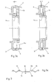
- a hub 2 is arranged on a shaft 1, which is connected to a first coupling half 3 on the one hand in a rotatable but axially secured manner and on the other hand is connected in a rotationally rigid but axially movable manner to a second coupling half 4.
- the torsionally rigid connection between the second coupling half 4 and the hub 2 takes place via disk packs 5, which are alternately connected to flanges in the second coupling half 4 and flanges in the hub 2 via screw points 5a distributed along the circumference.
- the two coupling halves 3, 4 each have a tooth profile 9a, 9b, which is shown in the form of a view in the upper region of FIG.
- the tooth profile in the area of the marking points 10 is widened to approximately twice the tooth width.
- the second coupling half 4 is connected to a pressure flange 6 which is supported against the hubs 2 via a plate spring assembly 7.
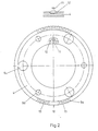
- the section along the line A-A shown in FIG. 2 shows the second coupling half 4 with its tooth profile 9a attached to the outer circumference and the bores 5a, 5b for the respective screw points of the known multi-plate connection.
- FIG. 2 corresponds to the right-angle assignment of the coupling half 4 shown to the coupling half 3, with a pin 11 attached to the first coupling half 3 lying in a recess 12 in the second coupling half 4.
- the pin 11 slides on the surface of the second coupling half 4 in the not yet switched on state (not shown in FIG. 2), it forms a support for the coupling halves 3, 4 against one another.
- the released state of the clutch is shown in Fig. 3a, which also shows a section along the line AA in Fig. 1, and the corresponding reactivated state in Fig. 3b.
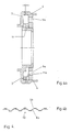
- the second exemplary embodiment of the invention shown in FIG. 4 differs from the first exemplary embodiment illustrated in that the tooth profile 9a, 9b is designed uniformly, that is to say has no widened tooth. Instead, another pin 11a serves as further support, to which a further recess, not shown, is assigned, into which pin 11a engages when the coupling halves 3, 4 are in the correct position.
- the two pegs 11, 11a lie on different pitch circles, so that one peg 11, 11a can only ever lie in the recess assigned to it.
- This design is particularly suitable where a uniform tooth profile is required for design reasons, in which case the two-point support of the coupling halves in the not yet switched-on state is formed by the two pins 11, 11a, which in turn are diametrically opposed.
Landscapes
- Engineering & Computer Science (AREA)
- General Engineering & Computer Science (AREA)
- Mechanical Engineering (AREA)
- Mechanical Operated Clutches (AREA)
Applications Claiming Priority (2)
| Application Number | Priority Date | Filing Date | Title |
|---|---|---|---|
| DE19883827672 DE3827672C1 (enExample) | 1988-08-16 | 1988-08-16 | |
| DE3827672 | 1988-08-16 |
Publications (1)
| Publication Number | Publication Date |
|---|---|
| EP0354988A1 true EP0354988A1 (de) | 1990-02-21 |
Family
ID=6360893
Family Applications (1)
| Application Number | Title | Priority Date | Filing Date |
|---|---|---|---|
| EP89111643A Withdrawn EP0354988A1 (de) | 1988-08-16 | 1989-06-27 | Wiedereinschaltbare Sicherheitskupplung mit gleichmässiger Abstützung |
Country Status (2)
| Country | Link |
|---|---|
| EP (1) | EP0354988A1 (enExample) |
| DE (2) | DE8816761U1 (enExample) |
Cited By (2)
| Publication number | Priority date | Publication date | Assignee | Title |
|---|---|---|---|---|
| FR2717231A1 (fr) * | 1994-03-11 | 1995-09-15 | Atec Weiss Gmbh & Co Kg | Accouplement de sécurité contre les surcharges pouvant être commuté par air comprimé. |
| EP2845834A1 (de) * | 2013-09-04 | 2015-03-11 | EFS-Gesellschaft für Hebe- und Handhabungstechnik mbh | Hebesystem, Überlastkupplung und Verfahren zum Betrieb eines Hebesystems |
Families Citing this family (5)
| Publication number | Priority date | Publication date | Assignee | Title |
|---|---|---|---|---|
| DE4007483C2 (de) * | 1989-03-21 | 1997-02-20 | Moenninghoff Gmbh & Co Kg Masc | Überlastkupplung |
| DE4040702A1 (de) * | 1990-12-19 | 1992-06-25 | Siemens Ag | Koppelvorrichtung |
| DE19815999B4 (de) * | 1997-08-25 | 2006-03-16 | Ktr Kupplungstechnik Gmbh | Überlastkupplung mit an Außen- und Innenumfang vorgesehenen Materialaussparungen |
| DE19756157C1 (de) * | 1997-12-17 | 1999-04-15 | Moenninghoff Gmbh & Co Kg Masc | Überlastkupplung |
| DE102005004053A1 (de) * | 2005-01-28 | 2006-08-10 | Audi Ag | Verstellbare Mittelarmlehne mit Überlastsicherung |
Citations (7)
| Publication number | Priority date | Publication date | Assignee | Title |
|---|---|---|---|---|
| GB326514A (en) * | 1928-09-13 | 1930-03-13 | Independent Pneumatic Tool Co | Improvements in or relating to clutches for screw or nut driving devices or the like |
| FR681212A (fr) * | 1928-09-21 | 1930-05-12 | Chicago Pneumatic Tool Co | Mécanisme d'embrayage |
| GB1026050A (en) * | 1964-03-24 | 1966-04-14 | Gen Motors Corp | Gas turbine safety coupling |
| FR2334004A1 (fr) * | 1975-12-04 | 1977-07-01 | Gelenkwellenbau Gmbh | Accouplement a disques pour raccorder des arbres |
| DE2821079A1 (de) * | 1978-05-13 | 1979-11-22 | Jakob Ing Grad Ludwig | Drehmomentbegrenzungskupplung |
| DE3018652A1 (de) * | 1980-05-16 | 1981-11-26 | Dierks & Söhne, 4500 Osnabrück | Knetmaschine |
| DE3700730A1 (de) * | 1987-01-13 | 1988-07-21 | Jakob Gmbh & Co Kg | Mechanische freischalt-sicherheitskupplung |
Family Cites Families (2)
| Publication number | Priority date | Publication date | Assignee | Title |
|---|---|---|---|---|
| DE7640820U1 (enExample) * | 1900-01-01 | Chr. Mayr Kg, 8951 Mauerstetten | ||
| DE1827231U (de) * | 1959-03-05 | 1961-02-23 | Eickhoff Geb | Ueberlastkupplung, insbesondere fuer bergbaumaschinen. |
-
1988
- 1988-08-16 DE DE8816761U patent/DE8816761U1/de not_active Expired - Lifetime
- 1988-08-16 DE DE19883827672 patent/DE3827672C1/de not_active Expired - Lifetime
-
1989
- 1989-06-27 EP EP89111643A patent/EP0354988A1/de not_active Withdrawn
Patent Citations (7)
| Publication number | Priority date | Publication date | Assignee | Title |
|---|---|---|---|---|
| GB326514A (en) * | 1928-09-13 | 1930-03-13 | Independent Pneumatic Tool Co | Improvements in or relating to clutches for screw or nut driving devices or the like |
| FR681212A (fr) * | 1928-09-21 | 1930-05-12 | Chicago Pneumatic Tool Co | Mécanisme d'embrayage |
| GB1026050A (en) * | 1964-03-24 | 1966-04-14 | Gen Motors Corp | Gas turbine safety coupling |
| FR2334004A1 (fr) * | 1975-12-04 | 1977-07-01 | Gelenkwellenbau Gmbh | Accouplement a disques pour raccorder des arbres |
| DE2821079A1 (de) * | 1978-05-13 | 1979-11-22 | Jakob Ing Grad Ludwig | Drehmomentbegrenzungskupplung |
| DE3018652A1 (de) * | 1980-05-16 | 1981-11-26 | Dierks & Söhne, 4500 Osnabrück | Knetmaschine |
| DE3700730A1 (de) * | 1987-01-13 | 1988-07-21 | Jakob Gmbh & Co Kg | Mechanische freischalt-sicherheitskupplung |
Cited By (3)
| Publication number | Priority date | Publication date | Assignee | Title |
|---|---|---|---|---|
| FR2717231A1 (fr) * | 1994-03-11 | 1995-09-15 | Atec Weiss Gmbh & Co Kg | Accouplement de sécurité contre les surcharges pouvant être commuté par air comprimé. |
| EP2845834A1 (de) * | 2013-09-04 | 2015-03-11 | EFS-Gesellschaft für Hebe- und Handhabungstechnik mbh | Hebesystem, Überlastkupplung und Verfahren zum Betrieb eines Hebesystems |
| US9528578B2 (en) | 2013-09-04 | 2016-12-27 | Efs-Gesellschaft Fuer Hebe- Und Handhabungstechnik Mbh | Lift system, overload coupling and method for operating the lift system |
Also Published As
| Publication number | Publication date |
|---|---|
| DE3827672C1 (enExample) | 1990-03-01 |
| DE8816761U1 (de) | 1990-05-31 |
Similar Documents
| Publication | Publication Date | Title |
|---|---|---|
| DE2715639C2 (de) | Gelenkwelle | |
| DE2508878C2 (de) | Torsionsdämpfende Kupplung, insbesondere für Reibscheiben von Kraftfahrzeugkupplungen | |
| DE3143163C2 (enExample) | ||
| DE3528591C2 (enExample) | ||
| DE3919783A1 (de) | Einweg-kupplung | |
| DE3206623A1 (de) | Torsionsdaempfungsvorrichtung, insbesondere reibkupplung, insbesondere fuer kraftfahrzeuge | |
| DE1188890B (de) | Stirnradgetriebe | |
| DE2707976C2 (de) | Reibungsschaltkupplung, insb. für Kraftfahrzeuge | |
| DE19526068A1 (de) | Differentialgetriebe | |
| DE3827672C1 (enExample) | ||
| DE3329259C2 (enExample) | ||
| DE3028467A1 (de) | Gelenk fuer ein drehmoment nach beiden drehrichtungen uebertragende wellen oder dergleichen | |
| EP0049903B1 (de) | Schraubtrieb mit Doppelmutter | |
| DE3630981A1 (de) | Lamelle fuer fluessigkeitsreibungskupplungen | |
| EP0025901A2 (de) | Elastische Kupplung | |
| DE2719765A1 (de) | Dynamische klauenkupplung | |
| WO1989008559A1 (fr) | Agencement de palier pour cylindre de pression d'un dispositif d'impression | |
| DE4007483C2 (de) | Überlastkupplung | |
| DE3418219A1 (de) | Vorrichtung zum daempfen von torsionsschwingungen, insbesondere reibkupplung, insbesondere fuer kraftfahrzeuge | |
| DE3535339C2 (enExample) | ||
| EP0009544B1 (de) | Überlastkupplung | |
| DE19722798C2 (de) | Kupplung | |
| DE69304017T2 (de) | Verbinderanordnung | |
| DE3805703C2 (enExample) | ||
| DE1927121C3 (de) | Rast- und Einstellvorrichtung |
Legal Events
| Date | Code | Title | Description |
|---|---|---|---|
| PUAI | Public reference made under article 153(3) epc to a published international application that has entered the european phase |
Free format text: ORIGINAL CODE: 0009012 |
|
| AK | Designated contracting states |
Kind code of ref document: A1 Designated state(s): AT BE CH DE ES FR GB GR IT LI LU NL SE |
|
| 17P | Request for examination filed |
Effective date: 19900223 |
|
| 17Q | First examination report despatched |
Effective date: 19910516 |
|
| STAA | Information on the status of an ep patent application or granted ep patent |
Free format text: STATUS: THE APPLICATION IS DEEMED TO BE WITHDRAWN |
|
| 18D | Application deemed to be withdrawn |
Effective date: 19911127 |