EP0354635A2 - Papiertransportsystem für ein opto-elektronisches Abtastgerät - Google Patents
Papiertransportsystem für ein opto-elektronisches Abtastgerät Download PDFInfo
- Publication number
- EP0354635A2 EP0354635A2 EP89302283A EP89302283A EP0354635A2 EP 0354635 A2 EP0354635 A2 EP 0354635A2 EP 89302283 A EP89302283 A EP 89302283A EP 89302283 A EP89302283 A EP 89302283A EP 0354635 A2 EP0354635 A2 EP 0354635A2
- Authority
- EP
- European Patent Office
- Prior art keywords
- rollers
- drive
- paper
- pressure plate
- idler
- Prior art date
- Legal status (The legal status is an assumption and is not a legal conclusion. Google has not performed a legal analysis and makes no representation as to the accuracy of the status listed.)
- Granted
Links
- 230000005693 optoelectronics Effects 0.000 title description 4
- 230000005484 gravity Effects 0.000 claims description 2
- 239000012858 resilient material Substances 0.000 claims 1
- 230000003287 optical effect Effects 0.000 abstract description 4
- 230000001360 synchronised effect Effects 0.000 abstract 1
- 239000002783 friction material Substances 0.000 description 2
- 238000010276 construction Methods 0.000 description 1
- 230000007257 malfunction Effects 0.000 description 1
Images


Classifications
-
- G—PHYSICS
- G03—PHOTOGRAPHY; CINEMATOGRAPHY; ANALOGOUS TECHNIQUES USING WAVES OTHER THAN OPTICAL WAVES; ELECTROGRAPHY; HOLOGRAPHY
- G03G—ELECTROGRAPHY; ELECTROPHOTOGRAPHY; MAGNETOGRAPHY
- G03G15/00—Apparatus for electrographic processes using a charge pattern
-
- H—ELECTRICITY
- H04—ELECTRIC COMMUNICATION TECHNIQUE
- H04N—PICTORIAL COMMUNICATION, e.g. TELEVISION
- H04N1/00—Scanning, transmission or reproduction of documents or the like, e.g. facsimile transmission; Details thereof
- H04N1/00567—Handling of original or reproduction media, e.g. cutting, separating, stacking
- H04N1/0057—Conveying sheets before or after scanning
Definitions
- This invention relates to a paper feed system for an opto-electronic scanner and more particularly to such a system which employs pinch rollers for driving the paper.
- system of the present invention is capable of operating a plurality of idler rollers which are spaced over a fairly large distance with a single lever.
- system of the present invention provides means for separating two sheets from each other, permitting only a single sheet to be fed through the rollers, this in the event that more than one sheet is inadvertently carried into the rollers.
- This improved operation is achieved in the present invention by employing a pressure plate which resiliently urges the idler rollers towards the drive rollers.
- the idler rollers are supported in elongated bearings for limited freedom of motion normal to their rotation axes.
- a release arm can be actuated to drive the pressure plate to a position whereat it does not drive the idlers permitting the idler rollers to move away from the drive rollers so that the paper can be removed or repositioned.
- a tension pad of friction material is provided which abuts against the upper face of the paper being fed through the rollers.
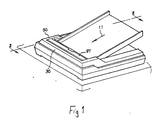
- Figs 1, 2 and 4 the preferred embodiment is shown in its normally operating conditions.
- the paper 11 to be scanned is fed past the scanner which includes a lamp 14 by means of pinch rollers formed by drive rollers 16, 17, and 18 which operate in conjunction with idler rollers 20, 21 and 22 respectively.
- the support shafts for idler rollers 21 and 22 are mounted in elongated bearings 21a and 22a respectively so that these rollers have limited freedom of motion along axes normal to their rotation axes.
- Pressure plate 29 has a pair of spring fingers 51 and 52 which abut against the idler roller drive shafts and resiliently urges these rollers towards their associated drive rollers such that the paper is pinched between the paired rollers.
- Pressure plate 29 is pivotally supported on the shaft 50 which in turn is mounted on the support frame 56.
- the top end of tension plate 29 is urged upwardly by means of springs 60 so that the portion thereof on the opposite side of pivot support shaft 50 which includes spring fingers 51 and 52 is urged against the idler roller shafts.
- the paper inlet pinch roller which is formed by drive roller 16 and idler roller 20 has a separate spring for urging the idler towards the drive roller and can be separately lifted manually in the manner of a conventional typewriter roller.
- the scanner may be of the type described in my Patent No. .pa 4,667,253.
- the drive rollers are driven by means of a motor (not shown) operating in conjunction with a series of drive belts 25 and 26 and others (not shown).
- Pressure pad 35 is fixedly attached to flat plate 36 which in turn is pivotally supported on pressure plate 29 by means of hinge pin 38.
- Pad 36 rests on the paper 11 by virtue of gravity but may additionally be urged against the paper by means of a spring.
- the pad is fabricated of a suitable friction material such as rubber and is positioned at an angle to the uppermost or stack of sheets 11 so as to impede its advancement.
- the bottom sheet,being in contact with the driver roller 62, which by design has higher friction than the friction pad 36, is pushed past pad 35 and further transported through the scanner by the rollers 17 and 18 and their associated idlers 21 and 22 respectively.
- Release lever 37 normally forms part of the top wall of housing 30 and is pivotally supported on support pin 41.
- lever 37 When lever 37 is positioned as shown in Fig 3, the end 37a thereof abuts against pressure plate 29 and drives this plate away from the idler wheels 21 and 22 leaving these wheels free from their associated drive wheels 17 and 18, the idler wheels being free to ride upwardly in their associated elongated bearings. In this manner the pinch rollers release their hold on the paper 11 so that it can either be withdrawn or adjusted in place as may be desired.
- the system of the invention thus provides a paper feeder for a device such an opto-electronic scanner having a paper release mechanism which operates to release widely separated pinch rollers with a single actuation of a lever.
- a simple yet highly effective mechanism is provided for separating multiple sheets from each other in the event that they should be inadvertently fed into the feed system at the same time.
Landscapes
- Engineering & Computer Science (AREA)
- Multimedia (AREA)
- Signal Processing (AREA)
- Physics & Mathematics (AREA)
- General Physics & Mathematics (AREA)
- Sheets, Magazines, And Separation Thereof (AREA)
- Delivering By Means Of Belts And Rollers (AREA)
- Handling Of Cut Paper (AREA)
Applications Claiming Priority (2)
| Application Number | Priority Date | Filing Date | Title |
|---|---|---|---|
| US230157 | 1988-08-08 | ||
| US07/230,157 US4958826A (en) | 1988-08-08 | 1988-08-08 | Paper feed system having a pressure plate that resiliently urges a plurality of elongated bearing, spring biased idler rollers against associated drive rollers for feeding a sheet of paper therebetween |
Publications (3)
| Publication Number | Publication Date |
|---|---|
| EP0354635A2 true EP0354635A2 (de) | 1990-02-14 |
| EP0354635A3 EP0354635A3 (en) | 1990-12-19 |
| EP0354635B1 EP0354635B1 (de) | 1993-12-29 |
Family
ID=22864152
Family Applications (1)
| Application Number | Title | Priority Date | Filing Date |
|---|---|---|---|
| EP89302283A Expired - Lifetime EP0354635B1 (de) | 1988-08-08 | 1989-03-07 | Papiertransportsystem für ein opto-elektronisches Abtastgerät |
Country Status (5)
| Country | Link |
|---|---|
| US (1) | US4958826A (de) |
| EP (1) | EP0354635B1 (de) |
| JP (1) | JPH0248347A (de) |
| KR (1) | KR920005302B1 (de) |
| DE (1) | DE68911789T2 (de) |
Cited By (1)
| Publication number | Priority date | Publication date | Assignee | Title |
|---|---|---|---|---|
| EP0554476A1 (de) * | 1989-09-22 | 1993-08-11 | Vision Ten Inc. | Verfahren und Vorrichtung zum Abtasten und Digitalisieren |
Families Citing this family (3)
| Publication number | Priority date | Publication date | Assignee | Title |
|---|---|---|---|---|
| US5160964A (en) * | 1991-06-28 | 1992-11-03 | Matsushita Electric Industrial Co., Ltd. | Image recording apparatus occupying a minimum amount of space |
| JP3556038B2 (ja) * | 1996-01-22 | 2004-08-18 | ニスカ株式会社 | 給紙装置 |
| US20060071422A1 (en) * | 2004-08-11 | 2006-04-06 | Klein William S | Pressure roller plate with force distribution |
Family Cites Families (16)
| Publication number | Priority date | Publication date | Assignee | Title |
|---|---|---|---|---|
| US2978088A (en) * | 1958-09-12 | 1961-04-04 | Ibm | Paper feeding device |
| US3948511A (en) * | 1973-11-19 | 1976-04-06 | Rank Xerox Ltd. | Sheet feeding devices |
| US4215945A (en) * | 1978-12-26 | 1980-08-05 | International Business Machines Corporation | Paper feeding apparatus |
| JPS5667858A (en) * | 1979-11-08 | 1981-06-08 | Canon Inc | Sheet registration mechanism releasing device |
| US4526358A (en) * | 1981-06-09 | 1985-07-02 | Konishiroku Photo Industry Co., Ltd. | Paper feeding mechanism |
| JPS6316531Y2 (de) * | 1981-06-19 | 1988-05-11 | ||
| US4491924A (en) * | 1982-04-22 | 1985-01-01 | The Babcock & Wilcox Company | Olefin oxidation reactor temperature control |
| JPS5992839A (ja) * | 1982-11-16 | 1984-05-29 | Minolta Camera Co Ltd | 給紙装置 |
| JPS59114238A (ja) * | 1982-12-20 | 1984-07-02 | Deyupuro Seizo Kk | 給紙装置における紙捌き機構 |
| JPS6099601A (ja) * | 1983-11-04 | 1985-06-03 | 大宮木材工業株式会社 | 斑取り作業用自動送り装置 |
| JPS60117866A (ja) * | 1983-11-29 | 1985-06-25 | Toshiba Corp | 画情報読取装置 |
| US4674735A (en) * | 1983-12-07 | 1987-06-23 | R. Clark DuBois | Automatic sheet feeder for copiers and other machines having sheet transport mechanisms and assemblies therewith |
| US4667253A (en) * | 1984-11-14 | 1987-05-19 | Chen Philip L | Optical line scanning imaging device |
| US4620807A (en) * | 1985-09-23 | 1986-11-04 | Xerox Corporation | Article transport for printers |
| US4898488A (en) * | 1986-08-22 | 1990-02-06 | Brother Kogyo Kabushiki Kaisha | Printer with multi-function paper feeding mechanism |
| US4763575A (en) * | 1987-04-06 | 1988-08-16 | Pitney Bowes Inc. | Envelope pressure plate for mailing machine |
-
1988
- 1988-08-08 US US07/230,157 patent/US4958826A/en not_active Expired - Fee Related
-
1989
- 1989-03-07 DE DE89302283T patent/DE68911789T2/de not_active Expired - Fee Related
- 1989-03-07 EP EP89302283A patent/EP0354635B1/de not_active Expired - Lifetime
- 1989-03-15 KR KR1019890003168A patent/KR920005302B1/ko not_active Expired
- 1989-03-20 JP JP1069128A patent/JPH0248347A/ja active Pending
Cited By (1)
| Publication number | Priority date | Publication date | Assignee | Title |
|---|---|---|---|---|
| EP0554476A1 (de) * | 1989-09-22 | 1993-08-11 | Vision Ten Inc. | Verfahren und Vorrichtung zum Abtasten und Digitalisieren |
Also Published As
| Publication number | Publication date |
|---|---|
| EP0354635A3 (en) | 1990-12-19 |
| DE68911789T2 (de) | 1994-04-14 |
| KR920005302B1 (ko) | 1992-07-02 |
| KR900003702A (ko) | 1990-03-26 |
| US4958826A (en) | 1990-09-25 |
| EP0354635B1 (de) | 1993-12-29 |
| DE68911789D1 (de) | 1994-02-10 |
| JPH0248347A (ja) | 1990-02-19 |
Similar Documents
| Publication | Publication Date | Title |
|---|---|---|
| CA1121752A (en) | Printer feeding and stacking | |
| JP3406395B2 (ja) | 給紙装置 | |
| US3734490A (en) | Document feeding mechanism | |
| CA2015885A1 (en) | Paper feeder | |
| JPS59118636A (ja) | 単一紙葉の分離装置 | |
| EP0546722B1 (de) | Blattausrichtungs- und Zufuhrgerät | |
| JPH0253341B2 (de) | ||
| CA1109497A (en) | Cartridge sheet feed attachment | |
| EP1741647B1 (de) | Papierzuführvorrichtung | |
| US4958826A (en) | Paper feed system having a pressure plate that resiliently urges a plurality of elongated bearing, spring biased idler rollers against associated drive rollers for feeding a sheet of paper therebetween | |
| EP0138442A1 (de) | Zuführeinrichtung für Briefumschläge | |
| US4573675A (en) | Document feeder | |
| KR960003347B1 (ko) | 시이트 이송방법 및 장치 | |
| EP0764602B1 (de) | Apparat zum Trennen von Blättern | |
| JPS63315435A (ja) | シ−ト材供給装置の重送防止装置 | |
| US5441250A (en) | Sheet feeding apparatus | |
| JP2602539B2 (ja) | シート給送装置 | |
| JP2557107B2 (ja) | シート材自動給送装置 | |
| JP3040537B2 (ja) | 新聞広告丁合機の給紙装置 | |
| JP2719479B2 (ja) | 紙葉類の分離装置 | |
| JPH01127532A (ja) | シート材の給送装置 | |
| JP3730016B2 (ja) | 用紙分離搬送装置 | |
| JP2800370B2 (ja) | 給紙装置 | |
| KR930002998Y1 (ko) | 복사기의 자동급지장치 | |
| JPH05155446A (ja) | 給紙装置 |
Legal Events
| Date | Code | Title | Description |
|---|---|---|---|
| PUAI | Public reference made under article 153(3) epc to a published international application that has entered the european phase |
Free format text: ORIGINAL CODE: 0009012 |
|
| AK | Designated contracting states |
Kind code of ref document: A2 Designated state(s): DE ES FR GB IT |
|
| PUAL | Search report despatched |
Free format text: ORIGINAL CODE: 0009013 |
|
| RHK1 | Main classification (correction) |
Ipc: B41J 13/00 |
|
| AK | Designated contracting states |
Kind code of ref document: A3 Designated state(s): DE ES FR GB IT |
|
| 17P | Request for examination filed |
Effective date: 19901231 |
|
| 17Q | First examination report despatched |
Effective date: 19920824 |
|
| GRAA | (expected) grant |
Free format text: ORIGINAL CODE: 0009210 |
|
| AK | Designated contracting states |
Kind code of ref document: B1 Designated state(s): DE ES FR GB IT |
|
| PG25 | Lapsed in a contracting state [announced via postgrant information from national office to epo] |
Ref country code: IT Free format text: LAPSE BECAUSE OF FAILURE TO SUBMIT A TRANSLATION OF THE DESCRIPTION OR TO PAY THE FEE WITHIN THE PRE;WARNING: LAPSES OF ITALIAN PATENTS WITH EFFECTIVE DATE BEFORE 2007 MAY HAVE OCCURRED AT ANY TIME BEFORE 2007. THE CORRECT EFFECTIVE DATE MAY BE DIFFERENT FROM THE ONE RECORDED.SCRIBED TIME-LIMIT Effective date: 19931229 Ref country code: ES Free format text: THE PATENT HAS BEEN ANNULLED BY A DECISION OF A NATIONAL AUTHORITY Effective date: 19931229 Ref country code: FR Effective date: 19931229 |
|
| REF | Corresponds to: |
Ref document number: 68911789 Country of ref document: DE Date of ref document: 19940210 |
|
| PG25 | Lapsed in a contracting state [announced via postgrant information from national office to epo] |
Ref country code: GB Effective date: 19940329 |
|
| EN | Fr: translation not filed | ||
| PLBE | No opposition filed within time limit |
Free format text: ORIGINAL CODE: 0009261 |
|
| STAA | Information on the status of an ep patent application or granted ep patent |
Free format text: STATUS: NO OPPOSITION FILED WITHIN TIME LIMIT |
|
| GBPC | Gb: european patent ceased through non-payment of renewal fee |
Effective date: 19940329 |
|
| 26N | No opposition filed | ||
| PGFP | Annual fee paid to national office [announced via postgrant information from national office to epo] |
Ref country code: DE Payment date: 20010228 Year of fee payment: 13 |
|
| PG25 | Lapsed in a contracting state [announced via postgrant information from national office to epo] |
Ref country code: DE Free format text: LAPSE BECAUSE OF NON-PAYMENT OF DUE FEES Effective date: 20021001 |