EP0353384B1 - Spanneinrichtung an Werkzeugmaschinen mit einem umlaufenden Spannzylinder - Google Patents
Spanneinrichtung an Werkzeugmaschinen mit einem umlaufenden Spannzylinder Download PDFInfo
- Publication number
- EP0353384B1 EP0353384B1 EP89106003A EP89106003A EP0353384B1 EP 0353384 B1 EP0353384 B1 EP 0353384B1 EP 89106003 A EP89106003 A EP 89106003A EP 89106003 A EP89106003 A EP 89106003A EP 0353384 B1 EP0353384 B1 EP 0353384B1
- Authority
- EP
- European Patent Office
- Prior art keywords
- clamping
- cylinder
- screwthreaded ring
- annular groove
- projection
- Prior art date
- Legal status (The legal status is an assumption and is not a legal conclusion. Google has not performed a legal analysis and makes no representation as to the accuracy of the status listed.)
- Expired - Lifetime
Links
- 230000008878 coupling Effects 0.000 claims 1
- 238000010168 coupling process Methods 0.000 claims 1
- 238000005859 coupling reaction Methods 0.000 claims 1
- 238000006073 displacement reaction Methods 0.000 description 4
- 238000000034 method Methods 0.000 description 1
Images
Classifications
-
- B—PERFORMING OPERATIONS; TRANSPORTING
- B23—MACHINE TOOLS; METAL-WORKING NOT OTHERWISE PROVIDED FOR
- B23B—TURNING; BORING
- B23B31/00—Chucks; Expansion mandrels; Adaptations thereof for remote control
- B23B31/02—Chucks
- B23B31/24—Chucks characterised by features relating primarily to remote control of the gripping means
- B23B31/30—Chucks characterised by features relating primarily to remote control of the gripping means using fluid-pressure means in the chuck
- B23B31/302—Hydraulic equipment, e.g. pistons, valves, rotary joints
-
- B—PERFORMING OPERATIONS; TRANSPORTING
- B23—MACHINE TOOLS; METAL-WORKING NOT OTHERWISE PROVIDED FOR
- B23Q—DETAILS, COMPONENTS, OR ACCESSORIES FOR MACHINE TOOLS, e.g. ARRANGEMENTS FOR COPYING OR CONTROLLING; MACHINE TOOLS IN GENERAL CHARACTERISED BY THE CONSTRUCTION OF PARTICULAR DETAILS OR COMPONENTS; COMBINATIONS OR ASSOCIATIONS OF METAL-WORKING MACHINES, NOT DIRECTED TO A PARTICULAR RESULT
- B23Q16/00—Equipment for precise positioning of tool or work into particular locations not otherwise provided for
- B23Q16/001—Stops, cams, or holders therefor
-
- B—PERFORMING OPERATIONS; TRANSPORTING
- B23—MACHINE TOOLS; METAL-WORKING NOT OTHERWISE PROVIDED FOR
- B23Q—DETAILS, COMPONENTS, OR ACCESSORIES FOR MACHINE TOOLS, e.g. ARRANGEMENTS FOR COPYING OR CONTROLLING; MACHINE TOOLS IN GENERAL CHARACTERISED BY THE CONSTRUCTION OF PARTICULAR DETAILS OR COMPONENTS; COMBINATIONS OR ASSOCIATIONS OF METAL-WORKING MACHINES, NOT DIRECTED TO A PARTICULAR RESULT
- B23Q17/00—Arrangements for observing, indicating or measuring on machine tools
- B23Q17/002—Arrangements for observing, indicating or measuring on machine tools for indicating or measuring the holding action of work or tool holders
- B23Q17/003—Arrangements for observing, indicating or measuring on machine tools for indicating or measuring the holding action of work or tool holders by measuring a position
-
- Y—GENERAL TAGGING OF NEW TECHNOLOGICAL DEVELOPMENTS; GENERAL TAGGING OF CROSS-SECTIONAL TECHNOLOGIES SPANNING OVER SEVERAL SECTIONS OF THE IPC; TECHNICAL SUBJECTS COVERED BY FORMER USPC CROSS-REFERENCE ART COLLECTIONS [XRACs] AND DIGESTS
- Y10—TECHNICAL SUBJECTS COVERED BY FORMER USPC
- Y10T—TECHNICAL SUBJECTS COVERED BY FORMER US CLASSIFICATION
- Y10T279/00—Chucks or sockets
- Y10T279/12—Chucks or sockets with fluid-pressure actuator
- Y10T279/1241—Socket type
- Y10T279/1249—Collet
Definitions
- the invention relates to a clamping device on machine tools, with a rotating clamping cylinder, an axially displaceable clamping piston arranged circumferentially in the clamping cylinder and with a coaxial cylindrical shoulder on the clamping cylinder with a diameter smaller than the clamping piston diameter.
- Clamping devices of this type are known for example from DE-OS 31 17 850. With them, the clamping piston always executes the same axial clamping path, even if a shorter clamping path would suffice from the clamping process.
- the invention has for its object to provide a tensioning device of the type mentioned in such a way that the stroke of the tensioning piston in the tensioning cylinder is limited in a simple manner and this stroke limitation can be adjusted as desired.
- the attachment has a coaxial thread on which a threaded ring is guided, which can be locked in its rotational positions on the attachment and has a coaxial undercut annular groove in its end face facing the tensioning cylinder, in terms of the Threaded ring axially non-adjustable, but slidable along the ring groove, stop bolts are mounted, which axially slidably and axially seal the end wall of the clamping cylinder in the cylinder space and form stops for the clamping piston.
- the threaded ring If the threaded ring is rotated on the shoulder, it adjusts itself axially accordingly and takes the stop bolts with it, which thus adjust axially in the clamping cylinder and thereby change the stroke limitation for the clamping piston.
- the stroke limitation and its adjustability mean that the full clamping path of the clamping piston does not always have to be extended, but the clamping path can be set to the actually required length and time can be saved due to the shorter clamping path.
- a preferred embodiment is characterized in that the annular groove has a radial mouth located on the inside of the threaded ring, through which the stop bolts with undercut bolt heads fitting into the annular groove can be inserted radially into the annular groove.
- the stop bolts are guided to several in the clamping cylinder so that they are arranged evenly distributed over the circumference of the cylinder.
- the device for fixing the threaded ring on the neck expediently consists of radial clamping screws arranged in the threaded ring and distributed over the circumference.
- the threaded ring can be turned by hand on the shoulder while the spindle of the machine tool is stationary. But there is also Possibility of providing a controllable drive device for rotating the threaded ring on the attachment, in particular a motorized drive device. Instead, however, it can also be advantageous to provide a controllable braking device acting on the threaded ring and a drive which rotates the clamping cylinder by a controllable angle in order to rotate the threaded ring on the attachment.
- the threaded ring is then held in place by the braking device while the drive rotates the clamping cylinder or the machine tool spindle carrying the clamping cylinder by the controllable angle, which angle can of course also be more than and multiples of 360 °.
- the arrangement is expediently made such that the drive or braking device acting on the threaded ring acts on the threaded ring via a clutch which can be engaged and disengaged.
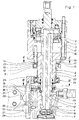
- the clamping cylinder 1 shown in the drawing for clamping devices on machine tools initially exists from a cylinder housing 3 with a displaceable clamping piston 2, which is connected on its right side in the drawing to a clamping rod, not shown, of a machine tool spindle, also not shown.
- the cylinder housing 3 is attached to the end of the machine tool spindle and rotates with it, including the clamping piston 2.
- a distributor is connected to the tensioning cylinder 1.
- This distributor 4 has a distributor housing 5 which does not rotate with the clamping cylinder 1 and which carries laterally lying connections 6 for the working medium actuating the clamping cylinder 1.
- a distributor shaft 7 rotates in the distributor housing 5, on which the distributor housing 5 is rotatably mounted and is held axially immovably.
- the distributor shaft 7 is fixedly connected to the tensioning piston 2 and is axially displaceably mounted in the wall of the tensioning cylinder 1 at 16. As a result, an adjustment of the tensioning piston 2 in the axial direction is transmitted unchanged to the distributor housing 5 via the distributor shaft 7.
- the circumferential grooves 12 on the inside of the distributor housing 5 serve for the supply and discharge of the working medium and are connected to the connections 6 for the working medium. Leakage oil passing through between the distributor shaft 7 and the distributor housing 5 is discharged through the connection 15.
- the distributor shaft 7 has two shaft channels 18 which lead into the clamping cylinder 1 on opposite sides of the clamping piston 2 and which are connected to the annular grooves 12. The working medium is controlled by the shaft channels 18 either on one of the two sides of the tensioning piston 2 in FIG usual way and requires no description.
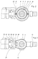
- a control device which consists of a touch switch 20 and two contact pieces 21, each with a control cam for actuating the touch switch 20.
- the touch switch 20 is connected to the distributor housing 5 and takes part in its axial displacement.
- a boom 29 is axially displaceably guided on the distributor housing 5 in a longitudinal guide 32 and carries the switching pieces 21.
- the cantilever 29 is fixed axially on the tensioning cylinder 1 with the aid of a bearing 24 which enables its rotation on a coaxial cylindrical extension 23 of the tensioning cylinder 1.
- the boom 29 is secured in the longitudinal guide 32 against rotating entrainment by the tensioning cylinder 1 and radially to the axis of the distributor housing 5 supported.
- a guide body 33 fastened to the distributor housing 5 is used to form the longitudinal guide 32.
- the longitudinal guide 32 is U-shaped in profile.
- the guide body 33 is provided with a carrier 35 for the touch switch 20 connected to the distributor housing 5 and is axially displaceable and held in its respective displacement position on the distributor housing 5, for which purpose clamping screws 36 are used, the nuts of which are used as slot nuts 37 in a T-slot 38 of the distributor housing 5 are movable.
- the shoulder 23 carries a coaxial thread 8 on which a threaded ring 9 is guided so that the threaded ring 9 rotates in the thread 8 and thereby its axial position on the neck 23 can be adjusted.
- the threaded ring 9 can be fixed on the shoulder 23, for which purpose radial clamping screws 10, which are distributed over the circumference and are guided in the threaded ring 9 and which can be tightened against the shoulder 23, are used.
- the threaded ring 9 In its end face 11 facing the clamping cylinder 1, the threaded ring 9 has a coaxial undercut annular groove 13, in which stop bolts 14 are suspended axially immovably with respect to the threaded ring 9, but are displaceable along the annular groove. These stop bolts 14 are axially displaceably guided and sealed in the end wall 16 of the cylinder housing 3 and project axially through the end wall 16 of the tensioning cylinder 1 into the cylinder space 17, where they form stops for the tensioning piston 2. In the exemplary embodiment, two such stop bolts 14 and three clamping screws 10 are provided.
- the annular groove 13 has a radial opening 19 lying on the inside of the threaded ring 9, through which the stop bolts 14 with undercut bolt heads 22 fitting into the annular groove 13 can be radially inserted into or removed from the annular groove 13.
- the bolt heads 22 are held in the annular groove 13 in an axially positive manner.
- the turning of the threaded ring 9 is carried out by hand with the clamping cylinder 1 stationary.
- a controllable motor drive device on the extension 23 or a controllable braking device acting on the threaded ring Connection to a drive rotating the clamping cylinder 1 to provide a controllable angle.
- the threaded ring 9 is held in place by the braking device, while the drive rotates the clamping cylinder 1 or the machine tool spindle carrying it by a predetermined angle or number of revolutions, which is provided for in modern machines anyway (controlled rotation about the C axis) is.
- the braking device must be such that it does not hinder the ring 9 secured against rotation with respect to the axial displacement occurring when the clamping cylinder 1 is rotated.
- the drive or braking device acting on the threaded ring 9 engage the threaded ring 9 via a clutch which can be engaged and disengaged, the clutch being only engaged while the threaded ring 9 is being rotated or braked .
Landscapes
- Engineering & Computer Science (AREA)
- Mechanical Engineering (AREA)
- Gripping On Spindles (AREA)
- Auxiliary Devices For Machine Tools (AREA)
Applications Claiming Priority (2)
| Application Number | Priority Date | Filing Date | Title |
|---|---|---|---|
| DE3826215A DE3826215C1 (enExample) | 1988-08-02 | 1988-08-02 | |
| DE3826215 | 1988-08-02 |
Publications (3)
| Publication Number | Publication Date |
|---|---|
| EP0353384A2 EP0353384A2 (de) | 1990-02-07 |
| EP0353384A3 EP0353384A3 (en) | 1990-10-24 |
| EP0353384B1 true EP0353384B1 (de) | 1992-03-25 |
Family
ID=6360078
Family Applications (1)
| Application Number | Title | Priority Date | Filing Date |
|---|---|---|---|
| EP89106003A Expired - Lifetime EP0353384B1 (de) | 1988-08-02 | 1989-04-06 | Spanneinrichtung an Werkzeugmaschinen mit einem umlaufenden Spannzylinder |
Country Status (5)
| Country | Link |
|---|---|
| US (1) | US4945819A (enExample) |
| EP (1) | EP0353384B1 (enExample) |
| JP (1) | JP2645524B2 (enExample) |
| DE (1) | DE3826215C1 (enExample) |
| ES (1) | ES2030931T3 (enExample) |
Families Citing this family (5)
| Publication number | Priority date | Publication date | Assignee | Title |
|---|---|---|---|---|
| DE4401142A1 (de) * | 1994-01-17 | 1995-07-20 | Roehm Guenter H | Spanneinrichtung an Werkzeugmaschinen mit einem umlaufenden Spannzylinder |
| DE19705362A1 (de) * | 1997-02-12 | 1998-08-13 | Heinz Dieter Schunk Gmbh & Co | Spannzylinder |
| US6874789B2 (en) * | 2002-07-24 | 2005-04-05 | Scimed Life Systems, Inc. | Low mass rotary motor assembly |
| US7080592B2 (en) * | 2004-01-08 | 2006-07-25 | Stephens Dynamics, Inc. | Rotating cylinder |
| US7603943B2 (en) * | 2007-02-14 | 2009-10-20 | Haas Automation, Inc. | Linear actuator for rotating shaft assemblies |
Family Cites Families (18)
| Publication number | Priority date | Publication date | Assignee | Title |
|---|---|---|---|---|
| DE930425C (de) * | 1952-12-14 | 1955-07-14 | Alfred Knecht | Luftfilter mit Ansauggeraeuschdaempfer und Starterschieber |
| GB739140A (en) * | 1953-11-03 | 1955-10-26 | John Conrad Arnold | Stroke adjusting and cushioning mechanism for fluid cylinders |
| FR1230498A (fr) * | 1959-02-12 | 1960-09-16 | Prec Ind | Broche de machine-outil à moteur hydraulique incorporé |
| US3167155A (en) * | 1962-12-04 | 1965-01-26 | Gen Motors Corp | Stroke positioning means for an actuator assembly |
| US3456955A (en) * | 1967-03-20 | 1969-07-22 | Gleason Works | Work seating and chucking diameter checking apparatus for workholders |
| US3807259A (en) * | 1972-10-26 | 1974-04-30 | Buck Tool Co | Draw-bar actuator |
| JPS5544266B2 (enExample) * | 1974-04-10 | 1980-11-11 | ||
| JPS51119475A (en) * | 1975-03-24 | 1976-10-20 | Westin & Backlund Ab | Position control device |
| SE391786B (sv) * | 1975-03-24 | 1977-02-28 | Westin & Backlund Ab | Legesregulator innefattande minst tva tryckoverforande element |
| US3999770A (en) * | 1975-07-28 | 1976-12-28 | Sollami Phillip A | Rotary cylinder and automatic collect holder |
| DE2534009B2 (de) * | 1975-07-30 | 1980-10-23 | Wilhelm Hegenscheidt, Gmbh, 5140 Erkelenz | Umlaufender Spannzylinder für Spanneinrichtungen an Werkzeugmaschinen |
| SU861773A1 (ru) * | 1979-11-13 | 1981-09-07 | Предприятие П/Я А-7676 | Устройство дл позиционировани пневмопривода |
| JPS5773205A (en) * | 1980-10-20 | 1982-05-07 | Sumitomo Metal Ind Ltd | High pressure control unit |
| DE3117850A1 (de) * | 1981-05-06 | 1982-11-25 | Günter Horst 7927 Sontheim Röhm | Spanneinrichtung an werkzeugmaschinen mit einem umlaufenden spannzylinder und mit einer kontrolleinrichtung fuer die axialverschiebungen eines im spannzylinder mitumlaufend angeordneten spannkolbens |
| DE3118583A1 (de) * | 1981-05-11 | 1983-02-10 | Wabco Westinghouse Fahrzeugbremsen GmbH, 3000 Hannover | Gangzylinder mit drei stellungen |
| SE8202293L (sv) * | 1982-04-13 | 1983-10-14 | Lofab Square Ab | Anordning for fastspenning av ett verktyg |
| JPS6099507A (ja) * | 1983-11-04 | 1985-06-03 | Kitagawa Tekkosho:Kk | 工作機械に於けるチヤツキング用回転流体圧シリンダ−装置 |
| US4825755A (en) * | 1987-04-23 | 1989-05-02 | Izimi Products Company | Piston-stroke adjusting mechanism of hydraulic tool |
-
1988
- 1988-08-02 DE DE3826215A patent/DE3826215C1/de not_active Expired
-
1989
- 1989-04-06 EP EP89106003A patent/EP0353384B1/de not_active Expired - Lifetime
- 1989-04-06 ES ES198989106003T patent/ES2030931T3/es not_active Expired - Lifetime
- 1989-06-22 US US07/370,247 patent/US4945819A/en not_active Expired - Fee Related
- 1989-06-30 JP JP1171011A patent/JP2645524B2/ja not_active Expired - Lifetime
Also Published As
| Publication number | Publication date |
|---|---|
| JPH0253506A (ja) | 1990-02-22 |
| EP0353384A3 (en) | 1990-10-24 |
| ES2030931T3 (es) | 1992-11-16 |
| JP2645524B2 (ja) | 1997-08-25 |
| EP0353384A2 (de) | 1990-02-07 |
| DE3826215C1 (enExample) | 1989-08-10 |
| US4945819A (en) | 1990-08-07 |
Similar Documents
| Publication | Publication Date | Title |
|---|---|---|
| EP0248917A1 (de) | Vorrichtung an einer Presse mit Exzenterwelle zum Verstellen des Stösselhubes | |
| CH619629A5 (enExample) | ||
| DE3114656C2 (enExample) | ||
| EP0245629B1 (de) | Spanneinrichtung an Drehspindeln von Drehmaschinen für kraftbetätigte Werkstückhalter, insbesondere Spannfutter | |
| DE3611324C2 (enExample) | ||
| DE1925527C3 (de) | Druckmittelbetätigtes Spannfutter | |
| DE69310579T2 (de) | Werkzeug-Ein- und Ausspannvorrichtung | |
| EP0353384B1 (de) | Spanneinrichtung an Werkzeugmaschinen mit einem umlaufenden Spannzylinder | |
| DE1477884B2 (de) | Spannfutter mit mehreren die Spannbacken aufnehmenden Schwenkarmen | |
| EP0302187B1 (de) | Spanneinrichtung an Drehmaschinen mit einem Spannfutter | |
| EP0739671A2 (de) | Wellenlager an einer Bearbeitungsmaschine | |
| DE3925284C2 (enExample) | ||
| DE925140C (de) | Druckmittelantrieb fuer die Backen von Spannfuttern | |
| EP0185170B1 (de) | Backenspannfutter für Drehmaschinen zur Bearbeitung von Werkstücken unter mehreren Bearbeitungsachsen | |
| DE2346849C2 (de) | Revolverkopf für Werkzeuge | |
| DE3232495A1 (de) | Vorrichtung zur kuehlmittelzufuhr zu mit kuehlmittelkanaelen versehenen, rotierenden schneidwerkzeugen fuer die spanende metallbearbeitung, insbesondere bohrwerkzeuge | |
| DE2626692A1 (de) | Spanneinrichtung an einer werkzeugmaschine | |
| EP0073361A2 (de) | Schraubstock | |
| DE3929011A1 (de) | Spanneinrichtung an werkzeugmaschinen | |
| AT399023B (de) | Einrichtung zur drehzahlabhängigen verstellung des relativen drehwinkels zwischen zwei drehgekuppelten bauteilen | |
| DE504800C (de) | Schleuderpumpe mit einem aus zwei Ringen gebildeten ringfoermigen Pumpenkanal | |
| DE2150041A1 (de) | Umlaufender spannzylinder fuer spanneinrichtungen an werkzeugmaschinen | |
| DE3212906A1 (de) | Werkzeug zur entfernung von absperrorganen | |
| DE3432279A1 (de) | Kontervorrichtung fuer ein schraubgetriebe | |
| DE3230458C2 (de) | Steuereinrichtung für eine Massagedusche |
Legal Events
| Date | Code | Title | Description |
|---|---|---|---|
| PUAI | Public reference made under article 153(3) epc to a published international application that has entered the european phase |
Free format text: ORIGINAL CODE: 0009012 |
|
| AK | Designated contracting states |
Kind code of ref document: A2 Designated state(s): ES FR GB IT |
|
| PUAL | Search report despatched |
Free format text: ORIGINAL CODE: 0009013 |
|
| AK | Designated contracting states |
Kind code of ref document: A3 Designated state(s): ES FR GB IT |
|
| 17P | Request for examination filed |
Effective date: 19901116 |
|
| GRAA | (expected) grant |
Free format text: ORIGINAL CODE: 0009210 |
|
| AK | Designated contracting states |
Kind code of ref document: B1 Designated state(s): ES FR GB IT |
|
| ET | Fr: translation filed | ||
| ITF | It: translation for a ep patent filed | ||
| GBT | Gb: translation of ep patent filed (gb section 77(6)(a)/1977) | ||
| REG | Reference to a national code |
Ref country code: ES Ref legal event code: FG2A Ref document number: 2030931 Country of ref document: ES Kind code of ref document: T3 |
|
| PLBE | No opposition filed within time limit |
Free format text: ORIGINAL CODE: 0009261 |
|
| STAA | Information on the status of an ep patent application or granted ep patent |
Free format text: STATUS: NO OPPOSITION FILED WITHIN TIME LIMIT |
|
| 26N | No opposition filed | ||
| PGFP | Annual fee paid to national office [announced via postgrant information from national office to epo] |
Ref country code: FR Payment date: 19980318 Year of fee payment: 10 |
|
| PGFP | Annual fee paid to national office [announced via postgrant information from national office to epo] |
Ref country code: GB Payment date: 19980324 Year of fee payment: 10 |
|
| PG25 | Lapsed in a contracting state [announced via postgrant information from national office to epo] |
Ref country code: GB Free format text: LAPSE BECAUSE OF NON-PAYMENT OF DUE FEES Effective date: 19990406 |
|
| PGFP | Annual fee paid to national office [announced via postgrant information from national office to epo] |
Ref country code: ES Payment date: 19990419 Year of fee payment: 11 |
|
| GBPC | Gb: european patent ceased through non-payment of renewal fee |
Effective date: 19990406 |
|
| PG25 | Lapsed in a contracting state [announced via postgrant information from national office to epo] |
Ref country code: FR Free format text: LAPSE BECAUSE OF NON-PAYMENT OF DUE FEES Effective date: 19991231 |
|
| REG | Reference to a national code |
Ref country code: FR Ref legal event code: ST |
|
| PG25 | Lapsed in a contracting state [announced via postgrant information from national office to epo] |
Ref country code: ES Free format text: THE PATENT HAS BEEN ANNULLED BY A DECISION OF A NATIONAL AUTHORITY Effective date: 20000407 |
|
| REG | Reference to a national code |
Ref country code: ES Ref legal event code: FD2A Effective date: 20020204 |
|
| PG25 | Lapsed in a contracting state [announced via postgrant information from national office to epo] |
Ref country code: IT Free format text: LAPSE BECAUSE OF NON-PAYMENT OF DUE FEES;WARNING: LAPSES OF ITALIAN PATENTS WITH EFFECTIVE DATE BEFORE 2007 MAY HAVE OCCURRED AT ANY TIME BEFORE 2007. THE CORRECT EFFECTIVE DATE MAY BE DIFFERENT FROM THE ONE RECORDED. Effective date: 20050406 |